Antipyretics for children are prescribed by a pediatrician. But there are situations of emergency care for fever, when the child needs to give the medicine immediately. Then the parents take responsibility and apply antipyretic drugs. What is allowed to give to infants? How can you bring down the temperature in older children? Which medications are the safest?
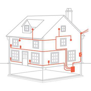
Building your own country house is the dream of every resident of the city. Just imagine how pleasant it is to work in the city all day, then tired to return to your countryside and breathe the fresh air. However, to arrange such a home will have to make a lot of efforts. Of course, the paramount task of any construction is the erection of walls, roofs and interior decoration in the house. However, at the time of the project development, the wiring diagram in the private house should already be clearly worked out, since no modern dwelling does not do without signs of civilization - a TV set, telephone, music center and other household appliances. If you do not pay proper attention to the design of the electrical part of the house, it will be very difficult to install electrical equipment. This should be remembered by any developer who is developing a wiring diagram at home with his own hands.
Why do we need a well-designed scheme?
As it became clear, it is necessary to think everything over before the construction starts. Of course, it is possible to build wires around the house even before finishing, with the proper experience of an electrician, however, the wiring diagram in a private house must be designed in advance. This will allow to take into account some moments for the maximum technological design of the "box" of living quarters. Besides:
1. The wiring diagram in a private house will provide a complete picture of the need to purchase all necessary consumables for installation: wires, junction boxes, sockets, switches and other trifles; running around each of them to the store will be extremely inconvenient during the work.
2. All necessary calculations are made in the design documentation for electrification to determine the required area and also the parameters of other devices - the switchboard, electricity meters, automatic overload protection, which will help to prevent an emergency situation.
How correctly to make the project?
The scheme largely determines not only the convenience of using all the existing electrical equipment in the future, but also the safety of this operation, so ideally it should be entrusted to the professional electricians who have already studied all the narrow and problematic areas. However, this does not mean that you can not do the project yourself. Let's discuss the basics that will be needed for this.
So, the most common variant of supplying electricity in the countryside is an air line with a voltage of 0.4 kV. On the input device of the circuit - input shield - comes from the overhead line three wires: the working PEN, phase L and zero protective. Recently, such an electrical board is installed outside the building. In this block there is an electricity meter and (we'll talk about them below).
The wires from the "receiver" get inside the house to the internal electrical panel, after which the wiring diagram in the private house branches out into several groups of main energy consumers:
- sockets;
- lighting;
- business group (sockets, light bulbs, switches in utility rooms, for example, store rooms or tool attachments, and other elements of the wiring diagram in the house);
- power group required to power large power devices - boiler, boiler, etc.
In order for electricity to be safe, the wiring diagram in wooden house (brick or block this also applies) should provide security devices for each of the groups described. What is it for? Imagine a situation where, for some reason, a short circuit occurs in the illuminating device. If there is only one circuit breaker in the switchboard, the light in the whole house will be cut down, which means that it will be much more difficult to repair everything. If the machines are in each group, then the house will not remain without electricity. If there are 2 floors, it is advisable to put a separate switchboard for both.
The sequence of devices to the boiler or bulb is as follows:
Introductory automatic machine, installed outdoors;
Electricity meter;
Internal single-band machine (suitable for single-phase wiring in the house), from which goes the zero or phase wires;
Zero bus;
Automatic machines for each of the phase wires (to sockets and so on);
Earthing bar.
The electrical wiring diagram in the wooden house is also a plan for calculating the length of the cables. Therefore, the best option is to display the elements on a separate sheet of the house plan. So you will carefully consider the placement of sockets, switches, light bulbs, etc.
Electricians are also developing circuit diagram electrical wiring, but this requires additional knowledge, so if you do it yourself, you can omit the item.
In principle, it does not matter, a wiring diagram is developed in the "Khrushchev" or wooden a country house. In any case, it is worth taking into account some provisions of the current world practice of electrical installation works that will help optimize the number of consumables and distribution points of the supply line without compromising the convenience of using electrical appliances: 
- The most convenient switch is the one that is located next to the door on the side of the handle attachment. The optimal placement option is at the breast level of an adult. First, it will be convenient for all members of the family (we will be supportive of the female half of the population, whose average growth is 10-15 centimeters less than for men). Secondly, the switch will be inaccessible to unnecessarily curious little babies.
- The layout of wiring for each outlet should not be random or evenly distributed around the perimeter of the room. As a rule, for convenience, it's better to depart from standards and symmetry - think about where stationary electrical appliances like a TV set, a computer will stand. It is in those places it is worthwhile to place and sockets. Do not be stingy at all, since the number of installed outlets does not spoil the interior of the room, but protects you from overloads that can arise as a result of using tees. Do not place the sockets too low, especially in children's rooms (here it is generally better to install a version with a closing lid or automatically hiding plugs).
- Do not underestimate the rated cross-section of the wires in order to save. In the best case, such savings will lead to frequent disconnection of the protective device, at worst - it is necessary to "open" the wall and transfer the burnt out wire. Believe me, it's much more expensive than buying immediately what you need.
- When laying wires along the building plan of the house, do not allow diagonal placement. As a rule, the main lines are parallel to the ceiling, and the necessary branches are made only at right angles. Of course, this somewhat increases the length of the wires, but it greatly simplifies the maintenance, and also protects you from electric shock when you need to hang a bookshelf. Just imagine what kind of danger you are exposing yourself if you drill a hole in the wall, not knowing exactly where the supply wire passes.
Wiring Wiring Modes
So, the wiring diagram in a panel apartment or a private country house has already been developed. Now you need to determine the features of the installation. They consist in the choice of one of the types:
- open;
- hidden.
As the name implies, when choosing an open variant, the wiring will be on the surface of the wall, ceiling and so on. Hidden installation - a complete "masking" of wires and power cables in the walls, under the sheets of plasterboard, over the hanging ceiling.
Features of open wiring
 Immediately it is necessary to distinguish the main advantages and disadvantages of these types of installation. The first one is impeccable in terms of service option. If the wiring diagram is not professionally developed by your own hands, at any time it may be necessary to intervene, for example, replacing any section of the wire with a more massive one with a larger cross-section. Just imagine that for this it will be necessary to disrupt the wallpaper section, to break the layer of plaster. This can be avoided by using a neat plastic box that is nailed to the wall while holding the wire inside. Of course, appearance will be somewhat spoiled.
If the installation of a wiring in a private house is carried out by wooden walls, it is best to avoid flush mounting, since wood is a fire hazard material that can easily ignite in the case of wires. You can resort to partial masking of the wires in the cable duct of a modern plastic skirting board. However, there is no need to overdo it, because the joint placement of power and lighting wires is unacceptable. Between them there should be a gap of about 2 mm. Therefore, two streams of electricity of different power are better divided into groups.
Features of the hidden wiring
![]()
When concealed installation "Punctures" in the calculations and laying of wires are unacceptable at all, but the aesthetics "off scale". The second version of the wiring layout will completely hide it in the wall structure or, for example, the ceiling.
The hidden scheme of wiring installation, in addition to aesthetics, has some requirements. Thus, all wires must have a sufficiently thick insulating layer, which will prevent mechanical damage to the metal part. Otherwise, the replacement of the wiring will result in a fairly large amount of money and the time spent on new repairs.
If the wiring is laid in a room with a high level of humidity, for example in a bath, sauna or pool, then with hidden installation it is better to choose wires with a PVC sheath that will prevent water from entering the wires.
Preparatory work
The design of electrical wiring in a private house is the basis of all further works. Installation - this is the final stage, however, it is no less responsible than drawing up the scheme. Therefore, before drilling grooves in the walls or nailing the box you need to do some preparation:
- The parameters of the developed scheme are systematically and accurately applied on the surface of walls, floor and ceiling - marking out, punching holes, preparing places for the installation of distribution boxes, junkets, sockets, switches.
- The exact calculation of the required amount of electrical equipment and consumables is made. In no case is it worth to buy the wires "back to back" with the available distances - there must always be some stock.
Optimal "purchase"
Now proceed directly to the calculation of the required amount of electrical equipment. With introductory and switchboard everything is clear - 1 introductory and 1 or 2 distribution (depending on the number of floors in the house). Circuit breakers are also calculated by the number of available wiring lines. But on the wires, switches and sockets it is worthwhile to dwell in more detail.
The length of the wires is determined after marking the walls for the following reasons:
- The distance between the shield and also from the boxes to the outlets and switches is measured. For each joint, it is worth adding at least 100 mm of stock on each side so that you can accurately and conveniently place the wires in the junction box without pulling them or breaking them.
- In the places of connection of outlets and switches there should also be a small reserve - about 50-150 mm (depending on the convenience of placement).
- If the wires pass through the corner of the room, then it is necessary to provide a compensating loop that will prevent tension and wire breakage as a result of deformation of the house structure when the foundation dries and subsides. The minimum supply of wire per loop is 100 mm.
Now a little about the outlet. Form the requirements in the list of recommendations: 
- As noted above, the sockets should be located as close as possible to stationary household appliances. At least, for every 10 square meters of an ordinary living room you need to place 2 sockets. Even better, if they are not single, but double: one - for a TV and some hair dryer, and the second - for a computer or laptop. If the amount of electrical equipment is more, then more outlets will be needed.
- In the kitchen, you need 1 larger outlet (if in the house of an electric stove), one for a refrigerator, one for an electric kettle, and the rest, if necessary, 1-2 for switching on a food processor, a mixer, etc., and 1 for a reserve.
- The bathroom can be useful for a permanent outlet for connecting a washing machine, and another - for a hairdryer, a curling iron, and so on.
- Be sure when planning the number of outlets, consider the probability of moving furniture in the room.
As for the switches, with them things are much easier - there will be enough one for each room, if the lamp is one. If there are several of them, then you can use a double or a built-in variant.
Safety devices - RCDs
If in your home you will lay electrical wiring with your own hands, the circuit of its connection must necessarily include an RCD, or protective connection devices. They provide safe operation of any electrical equipment, in particular, water-related - washing machines, shower cabins, dishwashers and water heaters. The principle of operation of such a device is simple - it differentiates the value of the current in the phase and zero wire. Under normal operation, the current difference is zero. If an abnormal situation occurs, a leakage to the ground wire may occur, resulting in an automatic disconnection of the circuit. Do not disregard this device because of its cost, since it can save human life.
Replacement of electrical wiring

Very often, it is not only necessary to lay the wiring in the new house, but also to replace it during the overhaul. In this case, you can observe a depressing picture, when the insulation of the wires became very hard and ready to crumble from a simple touch. Therefore, it is better to replace all the wires without exception, and also to reconnect the contacts in the sockets and switches (this is often not discussed, because you really want to change the old socket to the modern one, which is both comfortable and beautiful). Quality wiring will work very long, so both during replacement and initial installation do not save on the wires - to change them is much more difficult than the outlet or switch.
All electrical work takes its origin from the scheme. If you have a clear and well-thought-out scheme at hand, therefore, it will be quite easy to make out the layout of electrocommunications at home. In this article, we will discuss the question of how the wiring diagram is drawn up in a private house, its potential purpose and its pre-eminent factors.
Schematic representation of the locations of electrical consumers and wiring is necessary in order to first of all stock up all the necessary materials for work. If there is a circuit, then it is possible to quickly calculate the cross-section of conductors, their length and the number of other elements (sockets, distributors , switches).
For work on power supply to the house, it is necessary to attract special labor, while the wiring installation in a private house should have a designation as the cable entry was made. In the future it will come in handy.
In modern conditions and thanks to the development of various technologies, it is possible to conduct electricity in the house in two optimal ways:
- using underground cable laying in a special insulating material;
- and by air routes, if the distance from the house to the support will allow this. Otherwise, an additional post is installed.
Speaking of the airborne version of the input, it should be emphasized that conductors come to the main transformer of the house:
- phase (L);
- combined protective and working zero (PEN).
Important! Thus, home improvement is provided by single-phase power supply.
According to the new standards, they began to practice the installation of meters on the outside of the house, therefore, in addition to the room itself, there should be a shield and a subsequent machine. In such cases, it is also advisable to install an RCD in order to protect tenants from electro-injury.
From the input metering device comes the cable coming to the inner flap, and from it cables are routed all over the house. For complete reliability of electrification of home conditions, the network should be divided into several subsystems: for separate rooms, for the kitchen or dining room and rooms of high humidity (bathroom, bathroom).
Please note, the number of automatic machines in the electrical switchboard must necessarily correspond to the number of groups to which you divided the power supply. For large houses it is necessary to divide the systems into each separate floor (if necessary, combine with the garage and outbuildings).
What should I look for when drawing up the scheme?
In fact, there is no basic algorithm for drawing up schemes, all you need is to meet your own needs and not invent anything. Consider the following recommendations when designing a scheme for electricity in the house.

- Creating a scheme taking into account powerful consumers and household appliances, such as a washing machine, an oven, a refrigerator, you must take into account the installation of grounding. It is important to depict it on a diagram for clarity of execution of works. It is advisable to use three-wire conductors.
- Implement the prepared scheme is best with a cable structure with a cross section of at least 2.5 square meters. mm. Such dimensions are ideal for installation of sockets and lamps. Often used for lighting conductors with a cross-section of 1.5 square meters. mm.
- Try not to overload the sockets, it is important that the total power of connected consumers in one source does not exceed 4,5 kW. Therefore, it is necessary to carry out separately each outlet under the intended device.
This is how the three-phase wiring diagram looks in a private house.
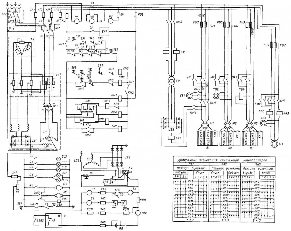
And this single-phase circuit, which is applied at least, despite the large number of electrical equipment in each house.

Follow the diagram and perform wiring
In order to correctly transfer the created scheme to reality, it is important to follow this simple algorithm:
- first of all we make an accurate marking of the walls. Draw the pencil with the places where the wires will be placed. Remember they go strictly in a horizontal position with a vertical drop or a lift to the outlets or switches;
Important! Do not carry out diagonal wiring to economize the material.
- sockets and switches are located at a certain distance from the floor. Of course, no one is using the old version any more, which means that they should be installed at a height of 25-30 cm from the floor, and 80-90 cm switches.
- make shtroby under the cable and podrozetniki. Place these devices so that they are convenient to use. Special fasteners are inserted in the finished stitches, however instead of them, plaster can be used, which will securely fix the wires in the channels, after which a layer of plaster is applied.
FROM electrical installation works in the private sector in our country is rather bad than good. For most mountain electricians, protecting a person from electric shock, and property from a fire, to great regret does not mean anything. At the same time, the impression is that ordinary users were skipping physics lessons at school and completely do not understand what is electricity. But they very well believe in marketing tricks and happily attack "branded" automation, rejecting any other.
I propose step by step to understand all the issues of electricity supply to a private country house with the example of single-phase input. Also this guide can be applied to the use in the apartment. Immediately, I note that my solution of particular nodes is the optimal balance between functionality and price, but without compromising security!
I hope there is no need to retell a full course of physics and explain what an alternating electric current is. We also omit the moments how this electric current appeared on the power station and through the step-up transformer got into the power line. I will only note the important nuance that the entire electricity supply system in Russia is three-phase. Single-phase voltage 220 volts in your outlet is only a phase voltage in one of the three phases. And the line voltage will be 380 volts. This circumstance should be taken into account in view of such a phenomenon as "phase skewing", which nevertheless is relevant only with the old wiring, not designed for modern loads.
2. So, the step-down transformer in the SNT. A high voltage of 10 kV comes on three wires. Further diverges 4 wires (3 phase and one zero conductor) through SNT. In the photo you see a modern transformer and bends in the form of CIP wires. At the moment, air lines in our SNT are undergoing modernization.
3. With a single-phase input, two conductors are connected to each consumer: phase and zero. In the photo you can see the old aluminum wires on the support nearest to the house. The tap to the house has already been made using a CIP wire. Particular attention is paid to the fact that all air line supports must have a grounding of the zero conductor (right upper photo). This is necessary in order to exclude emergency situations, such as a "zero break". In this case, you should pay special attention to your own grounding in the absence of repeated grounding on the intermediate supports, otherwise in an emergency your own grounding may be unique for the whole village.
4. Closer to the point. The last section of the air line from the nearest post to the building is stretched by the CIP wire, in our case 2х16. Stands for self-supporting insulated wire, it is aluminum with a cross section of 16 mm². For ease of installation and laying in place of the anchorage with the help of special clamps (wire SIP means the installation of the line under tension, at special terminals the nut is not under tension, and also has a rupture thread guaranteeing the necessary tightening force) passes into the VVG section of at least 10 mm² . It is in this form that two wires enter the lead-in shield. In the shield we have an introductory bipolar machine and an overvoltage limiter (always on the final support during air entry), which will protect the network when lightning strikes the phase conductor of the overhead line. It is connected in front of the machine to the phase conductor. Here in the shield there is a connection of the grounding strictly up to the input automaton. We are considering the TN-C-S grounding scheme, since the TT system is still designed for mobile buildings, rather than permanent buildings, and it has its own characteristics for security requirements. Disadvantages of the TN-C-S system proper installation no. Even if you go deeper into this topic, if you make a TT, it will be only your final section, while the whole air line from the transformer will be TN-C.
5. Mandatory grounding. Three corners with a wall of 50 mm (steel thickness of 5 mm), 2 meters in length, are driven into the ground by a sledge hammer and welded together in a triangle shape. To the wall of the house there is a steel strip with a width of 40 mm. The last meter to the shield is made with a copper conductor of at least 16 mm². Underestimating the cross-section is absolutely impossible, in case of any accident on the line, your grounding can become the only one for the entire line / street / block. Switching in the shield is as follows. The combined PEN (Protected Earth + Neutral) conductor from the overhead line is divided into two buses on N and PE. After that, the input automaton is switched, next to it is an overvoltage limiter. From the machine line goes to electric meter. Directly into the house goes three-wire copper wire with a cross-section of each conductor of 6 mm². The phase and zero conductors come from a meter grounding from the corresponding bus.
6. We pass to internal wiring at home. I repeat that when designing electrical network the principle of reasonable sufficiency. Of course, it was possible to make 2 times more outlets and to increase the number of lines of force by the same amount, but I think that this is absolutely not necessary. Explanations to the scheme: red squares - junction boxes, yellow circles - lamps. Blue indicates wiring in the screed, red in the walls. Everywhere in the house is used only lED lightening (the total consumption of all lamps included at the same time is below 300 watts). The lighting is powered from the power line to a specific room, I do not see the practical need for separation, besides, it significantly increases the amount of installation work. The diagram shows all existing consumers in the house. If you have questions, ask.
7. So, let's get started. This is a temporary electrician for the period of construction work. We pass to the laying of the lines of force. A total of 10 of them. Some of them will go along the walls, some in the floor in the corrugation.
8. Let's start with the floor lines. We use a NYM cable with a cross-section of 3x2.5 mm² in corrugation (gray corrugation does not burn at all, black does not support combustion and has protection against ultraviolet radiation. In a screed, it is not particularly important what to use, it is not so easy to find a strong gray, and I would trample soft preparatory work). The frequently asked question is why is it not the VVG? In terms of performance, they are completely identical, but the NYM has the advantage of triple insulation, while it has the drawback of a non-UV-resistant shell. Therefore, for open wiring, VVG is preferable. Otherwise, NYM is more convenient, including because of its round shape (a round VVG also exists, but it is extremely difficult to find it). In the corrugation with a diameter of 16 mm round NYM stretches elementary, which is extremely convenient. For memory it is worth to document the lines of laying the lines on the floor, although nowhere else but the door thresholds there is even a theoretical probability that you need to drive something into the concrete floor screed.
9. Corner of the kitchen area. Aerated concrete is simply an excellent material for processing - you can even use a screwdriver to wall the walls. So, we drill the holes for the mounting and junction boxes. Wire in the walls of NONGORYUCHYh grounds is laid in the form in which it is. No corrugations are required. All attention to the trails. Power lines are laid only at right angles. The main line goes along the floor at a height of 20-30 cm, then to the outlets and switches it rises strictly VERTICALLY. Diagonal gasket is prohibited and risky to get into the wire, for example when driving a nail into the wall (and so you know for sure that you can not drive nails exactly under the outlets and above the switches). The cable is fixed to the wall using plastic round staples (two holes are drilled, a bracket is inserted).
10. The floor screed is flooded. The question at what stage to lay the cable on the wall is solely from your personal preferences. Someone first plaster the walls, then make the stroba, lay the cable and seal the stroba back. I prefer to do the wiring before plastering the walls. This method may seem inconvenient because will require increased attention during the plastering works to the points with the mounting boxes (it is necessary to shut them up and then pick them up). Pay attention to the left corner - all the commutations on the pass-through lines of the outlets are not made in the podzheetniki, but in separate junction boxes.
11. I will repeat with the type of wires. NYM is the ideal and versatile cable. The cross-section is selected in accordance with the load. Usually use a cable 3x2, 5 mm². For powerful consumers, such as electric the hob may require a wire with a cross-section of 4 mm². For lighting lines where LEDs are used in my case (the maximum power consumption in the largest room is 80 watts), I use a cable PPPP 2x1.5 mm2 (there is no need for grounding in the lighting network, it has nowhere to connect). In general, the regulations prohibit the use of the PPP because technical conditions allow to understate the cross-section of veins up to 30% in comparison with the standards, and with general economy, this can cause a fire everywhere due to exceeding the permissible load. In my case, my maximum load more than 30 times less than can safely pass the cable with a cross-section of 1.5 mm². Therefore, a larger section is not required, and for installation of the lighting line this cable is most convenient. Yes, please note that for fixed wiring use only a rigid cable with a monobloc. Dashboards and junction boxes are mounted in the wall on a building plaster (alabaster), as the quickest drying solution.
12. Now directly the stage of assembly and installation of power lines. It will take several convenient tools. The topmost is used for crimping the tips multicore cables, for example PV3 (currently replaced by POGV), which are used when assembling the electrical panel. The middle tool is useful for quickly stripping the cable sheath NYM - clamped, cranked, pulled. Below is a simple tool for stripping the final veins, not quite convenient, but for one-time work more than enough.
13. It is still necessary to have such a thing as an indicator screwdriver. There are two varieties of them. The original device with a neon lamp without a power source is able to detect only the phase voltage. This is a simple Chinese device with a power supply has more advanced functionality and allows you to determine not only the phase (it is important to determine the phase can not be touched with the fingers of the screwdriver cap), but also the integrity of the line, as well as the place of wire breakage. On the right is the initial blank for the electrical shield. When switching it is important to distribute everything in such a way that it is intuitively clear where everything is.
14. At once I will note the nuance to which the "experts" must necessarily dig up - the zero conductor should be blue, and I have it black, since in our tree under the name of Moscow there is never anything in stock at the moment when I need it obviously single-phase, a clear catastrophe and the error of confusing zero with the second phase is not here). For switching in the electrical panel I use wire PV3 (it is possible to take a modern POGV) with a cross-section of 6 mm². Also, it will need special NSTHI tips (the tip of the pin bush insulated), they are needed in order to assemble together stranded wire before switching under the screw (veins spread out - there may be bad contact). It is also convenient to use special single-pole and bipolar buses (on the right photo in the background) to connect a number of circuit breakers.
15. Switching in junction boxes is as follows. WAGO 2273 terminals (on the left) are used on conductors with a cross-section of 3x1.5 mm² (why and why - later) and WAGO 222 (right) on conductors with a cross-section of 3x2.5 mm². Always follow the color marking conductors. WAGO 222 series is probably the best option, if there is no desire to work with soldering and crimping.
16. Installation of sockets and switches. I really like Schneider Electric products, the Unica series. Switches on modern standards should be turned down. Switching up is an old school since the time of the knife switches, the inclusion of which up was due to their design. Unica switches are turned down, this is their nominal position.
17. Switching double sockets standing next to next. The power cable comes to the terminals of one outlet, and then a branch is made to the adjacent one. The rules of good tone prescribe for the installation of sockets to connect the phase conductor to the right.
18. We return to the electric shield. Just want to pay attention - always take a shield with a very large margin, more than just will not. I kind of made it to the minimum, and almost all 36 positions (3 rows of 12 positions) were occupied. Be sure to leave a supply line of lines of force equal to a minimum of one and a half height of the shield. On the right you can see the first version of switching, and in fact this is the moment when the house was switched from a temporary electrical circuit to a constant. In the process, a couple of consumers appeared and the scheme was slightly refined.
So, I tell in detail what, how and why. Go!
A few words about the components of the scute.
A circuit breaker or just an automaton. Provides protection against short circuit, and also provides protection electrical wiring. Hence it contains two releases - electromagnetic and thermal, respectively. The first is triggered in the event of a short circuit on the line, the response time is determined by the time-current characteristic, which in any case is several times higher than the current rating of the machine. Thermal release is a bimetallic plate with different coefficients of thermal expansion and is designed to protect electrical wiring. It is in accordance with the cross-section of the cable and the sockets used that the nominal value of the machine is selected. The most popular mistake to put on a power line with a wire 2,5 mm² automatic to 25A from the calculation that the cable will withstand. No you can not. And the reason is rosettes. Conventional outlets are rated for current up to 16A. Therefore, this should be the value of the machine. And in general as a whole it is better to be reinsured and reduce the denomination of the machine, that is it will be able to protect the wiring from overheating or, worse, a fire.
RCD is a protective device that fixes the leakage current. The simplest mechanical device is a differential current transformer. If we explain on the fingers, then the amount of current that "came" along the phase conductor should be equal to the amount of current that "left" along the zero conductor. If the "left" is less than "came" - there is a leak, protection works. If there is a ground, the RCD will work as soon as there is a dangerous voltage on the housing of the device, if there is no ground, the RCD will work as soon as the person touches it (it will be hit with a little shock). From this it follows that the RCD must always be used, and the presence of grounding only increases the level of safety. At the same time, it is strictly forbidden to do homemade grounding in the apartment in the absence of it, the consequences can be very sad. About the RCD, it should be noted that it needs to be protected from the short-circuit current itself, so after it, there should be an automaton (s) with a lower nominal value than the RCD itself. The nominal value of the RCD itself implies on which maximum current it is calculated, it is better to focus on a 20-30% margin from a constant load. The simplest method check the operation of the RCD and the correct earthing - connect the neutral and ground conductors in the socket. The RCD must be disconnected immediately.
To sum up: the circuit breaker protects the wiring and equipment, the RCD protects the person. Still there are difa automats (here and earlier I use the terminology that has developed in our country, although it is not quite accurate), a device that combines the functions of an automaton and an RCD.
Now go to the dashboard:
We start from the upper left corner. Here comes the cable 3x6 mm² from the street shield. Introductory RCD with a leakage current of 300 mA. The people are called "fireproof". It is used in combination with an RCD for a smaller leakage current in the first place to ensure selectivity in the event of a trip (in the first place, the "lower" RCD will knock out), and secondly to increase fault tolerance. Next to it is the ABB C11 meter used by me exclusively for the technical metering of electricity (to report to you the figures of consumption of the air heat pump and not to run for it to the street shield). After it there are two bipolar automatic devices that also perform the role of knife switches. The left, with a rating of 40A is used to de-energize the entire electrical system of the house except for an air heat pump. Right, respectively, controls the air heat pump). To the right there is a thermostat of the anti-icing system (20 meters of heating cable in the gutter and drains) and three automata: for it and two lines of street outlets (which in turn are powered from one RCD from the next row).
Second row. In the left corner there is a common grounding bus for all lines. Pay attention to the commutation. It is not necessary to lay wires behind racks, it is better to conduct them as openly as possible. Further, we have a line of RCDs in the amount of 6 pcs, over which all consumers in the house are evenly divided. The leakage current of all RCDs is 30 mA, although ideally for a bathroom it is worthwhile to use an RCD with a leakage current of 10 mA.
Third row. Consumer end machines on lines. On the left, right and below, there are corresponding zero buses leaving from a specific RCD for each line. They must be separate, otherwise there will be no sense in separating the RCDs by separate lines. The automatons are grouped according to the type of load.
How to choose the rated current of the machine? As we have explained above, the machine's rating is chosen based on the conductor section (copper conductor cross-section 2.5 mm² withstands 25A long-term load) and switching devices (household outlets are rated for current up to 16A). Translate amperes into watts all know how to multiply by voltage (220 volts).
20. Close-up of the lower row of machines. Single-core cables are directly connected to the screws, the stranded ones must first be pressed with a tip. There are many unreasonable claims of "experts" to IEK products and very vain. This is an excellent option for the ratio of price / quality. They are made in China, Russia and Turkey. And they perform their function no worse than the "racially-faithful" ABB and Legrand. Do not believe me? Ask real electricians, not charlatans, who are vparivayuschih more expensive. The whole of Moscow after the recent modernization is electrified on IKE automation, of course, in a millionth scale, the quantitative statistics of failures will be higher than in the case of other brands, which are used in the residential fund by several orders of magnitude less. What's wrong with IKE? And nothing that can harm a person. The RCD or the machine after operation will simply not turn back on and will require replacement. That's all.
21. Assembled flap assembly.
22. And layout on lines with signatures. Simple and functional. The colors are grouped by lines. If an accident occurs, for example, on a line with a pump, only it will be disconnected, and the power supply of the whole house will not be affected. To many, such an amount of RCD may seem redundant. Indeed, a sufficient minimum is one input RCD for the entire facility with a leakage current of 30 mA. Remember - the RCD must always be. Even if your apartment does not have a modernized input and uses a TN-C connection with two wires. Yes, you do not have a separate ground, and the RCD does not work out the situation of phase leakage to the body of the device without the "help" of a person. But the RCD protects the person.
23. Well, the final types of sockets in the premises. Let me remind you that on the outgoing lines the machine should not exceed the nominal value of 16A (for me, for example, the line to the bedroom is made with a NYM 3x1.5 mm² cable (I do not see the need to include more than 2 kW there), and therefore the machine on this line has a nominal value current 10A.
24. And about the lighting of a couple of words. Everywhere in the house are inexpensive lamps for the cartridge GU10. Of lED Light Bulbs I ordered several models from China for tests, and also took "Russian China" under the brands Camelion and Woltra. At the last price of about 230 rubles per lamp - I will honestly say that buying something from China is pointless. All samples at a price of less than 150 rubles apiece have a serious spread over color temperature, not to mention too low (Ra<70) индексе цветопередачи.
Everything that concerns electrical networks is described in detail and understandably in
Power supply.
The project of electricity supply of a residential house is designed on the basis of:
1. Technical specifications of the customer;
2. Contracts;
3. Architectural planning and design project of a residential building,
4. Normative documents acting on the territory of the Russian Federation:
PUE 2002. "Rules for the installation of electrical installations", edition 7;
GOSTs Р50571 "Electrical installations of buildings";
SNIP 23-05-95 "Natural and artificial lighting";
NPB246-97 "Fire Safety Rules in the Russian Federation".
The scope of the project includes electric lighting of premises and power electrical equipment (sockets). According to the composition of the electric consumers envisaged, the projected residential house corresponds to the housing of the 2nd category. According to a one-line scheme, the one-time load of a residential house is 16.75 kW. The total claimed capacity of the apartment is 27.25 kW. The demand coefficient is 0.62. Given the design load, the input into the residential house is designed three-phase and is performed at a voltage of 380 V 50 Hz with a deadly grounded neutral.
To distribute electricity to consumers in a residential building, a switchboard SHCHR and a one-room apartment block of individual manufacture are used. The single-line scheme is shown in Fig. In order to provide additional fire safety at the entrance to the SCB panel, after the water machine, a protective shutdown device (RCD) with a set point of leakage current of 300 mA is installed.
The organization of electricity metering for the projected residential building is envisaged in the existing street switchboard by a counter of a double active energy tariff, three-phase, direct-flow, type is specified 380/220 V, 5-50A. All outlets are selected in accordance with the requirements of the PUE clause 7.1.49.
In the design of the place of installation of lamps, sconces, boxes for the hanging of chandeliers, sockets and wiring accessories are recommendatory in nature and specified by the Customer depending on the interior solutions. The choice of luminaires should be made depending on the purpose and environment of the room. The minimum degree of protection of luminaires and sockets, installed in the premises of bathrooms and bathrooms, must be at least IP44.
The electrical wiring of the outlet and power network is carried out in corrugated PVC pipes with a cable with copper conductors of the grade ВВГнг not less than 2.5 mm. sq. m. in strobes of building designs of walls.
Wiring lighting network is carried out in corrugated PVC pipes with a cable with copper veins VVGng-ls in the stitches of building structures of walls, ceilings and behind the false ceiling.
Concealed wiring should be replaceable, with the possibility of replacing the cable, as well as access to the branches and electrical installation products. The electrical wiring pipes must have a fire safety certificate and be securely attached to the ceilings, walls and partitions. When designing, it was taken into account that the building structures of a residential building are fireproof.
Connection, branching and termination of cores of wires and cables should be made by means of crimping, welding, soldering or clamping (screw, bolt, etc.)
To ensure easy identification of the wiring harnesses by the colors, in accordance with clause 2.1.31 of the UEU 7th edition, the project accepts conductors:
Black, brown and red colors for the designation of phase conductors (L1, L2, L3)
Blue - to indicate the zero conductor (N),
Yellow-green - to indicate the protective conductor (PE) /
The height of installation of electrical equipment and wiring products from the level of the clean floor is: switches of electric lighting - 0.9 m; Outlets - 0.3 m; distribution board - 1.5 m. The places and height of the points of supply of the group network to the current receivers are specified in accordance with the specific types of equipment used. In accordance with GOST R 50571.2-96, PUE chap. 7 in the draft adopted:
Type of grounding system - TN-S;
Types of systems of current-carrying conductors: from a street board to a switchboard, a five-wire distribution board. The house network is three-wire.
In order to protect people from electric shock, all open conductive parts of electrical installation that can be energized as a result of insulation failure must be grounded by attaching them to the protective conductor PE. For this purpose, separate conductors are used - the fifth or third conductor of the supply network, which is connected to the main protective conductor - the PE bus of the switchboard of the switchboard. When grounding, refer to SNiP 3.05.06-85 section "Earthing devices" and SP31-110-2003 section "Grounding (zeroing) and protective measures of safety", as well as PUE. 7, chapter 1.7. Sockets should have a closing socket device.
For bathrooms and shower cabins, an additional potential equalization system is provided, which is realized by connecting the metal bodies of baths, showers, pallets and pipes to the equipotential bonding box (PSC), which, in accordance with GOST 50571.11-96, is installed in the bath and shower area. The connection of the PCU to the PE busbar of the house board is carried out using copper conductors of 6 mm cross-section. sq. m. (a cable of grade ВВГнг 1х6). From the PMC to the electrical equipment (protective contacts) and external conductive parts, PVC pipes are made, made with the cable VVGng 1x2.5. Electrical equipment installed permanently in sanitary warehouses must also be connected to the equipotential bonding system with a copper conductor (BBNng 1x2.5) laid in corrugated PVC pipes.
Electrical equipment and materials accepted for installation, including foreign production, and similar in return for those specified in the project, must be certified in the GOST RF Certification System, as well as in the field of fire safety in accordance with NPB246-97 (in accordance with the List approved by the Main Administration of the Ministry of Internal Affairs of the Russian Federation ) and meet the technical specifications specified in the project, without impairing the quality. All electrical installation work must be carried out by qualified personnel licensed to manufacture these works, in compliance with the current standards of electrical and radiation safety and SNiP, as well as safety.
Format dwg
Not so long ago, owners of private houses connected to the power lines independently. The controlling organizations needed only to apply, and also to install a counter. Today the situation has radically changed. To connect to the power grid, you need to provide a project describing the ways of supplying all the appliances installed in the house (boiler, column, etc.). That is, the package of documents necessary for obtaining permission must necessarily contain a single-line diagram of the system that ensures their operation. About how to make it up, and how to arrange electricity supply to a private house correctly, and we'll talk further.
The project of electrification of a country house. A three-phase or single-phase network?
Of course, before drawing any schemes and going through the connection, it will be necessary to decide on the type of electricity supply, its source, and so on.
In private houses, as in urban apartments, a three-phase or single-phase network can be used. Both kinds have both their shortcomings and virtues. Initially, any industrial network has three phases. In high-rise buildings they are usually distributed among the apartments. However, due to the difference in the number of electrical appliances used, the load on the phase wires often varies. As a result, the neutral wire sometimes burns out. In a private house, such problems usually do not arise, since the owner alone, and therefore, control the load in the distribution of phases is much easier. However, if the network is misused, all sorts of problems - up to the failure of electrical appliances - can arise in this case. To prevent such trouble, you should use a stabilizer, which is very expensive. In addition, it will be necessary to purchase equipment and elements designed specifically for a three-phase line. That will also fly in a pretty penny. Therefore, a three-phase power supply scheme for a private house should be used when there really is a need. That is, if it is supposed to install very powerful instruments or equipment - machines, electric stoves, etc.
The advantage of single-phase networks is the relative cheapness and ease of use. The disadvantage is not too high power. It is more expedient to mount such a network in small residential or cottage houses.
Autonomous power supply
One of the important conditions for comfortable living in any building is the constant availability of current in the network. However, unfortunately, when the power supply of a private house is made from a common power line, there are often problems associated with interruptions in its supply. A good way out of this situation may be the additional use of autonomous power supplies. To such it is possible to carry:
- UPS. In the event of a power outage, this device begins to function instantly and automatically.
- Generator. Such equipment operates on gasoline, diesel or gas. It can also be turned on automatically. The operating time depends only on the amount of fuel. With sufficient power, the generator can supply even a very large house with electricity for a long time.

How to get permission to connect
So, with the number of phases, a variety of additional power supplies, etc., you are determined. What next? In what order does the private house connect to the power line? The power supply of suburban buildings is controlled by the network supply company in whose area of responsibility they are located. To her specialists and will need to apply by collecting the necessary package of documents. Their list should be known in advance.
After receiving the documents, the grid company will prepare technical conditions for the electricity supply to the private house. Most likely, they will have to be coordinated with various related organizations. Further the contract is concluded. After the network is mounted, the representative of the network organization arrives at the site and performs its verification for compliance with the requirements set forth in the technical conditions. The inspection is carried out with the participation of all interested parties. Rostekhnadzor is then given permission to operate the network.
Single line diagram
First, let's see what, in fact, is a drawing. The one-line scheme is, in fact, the same basic, but executed in a simpler form. That is, all the trunk lines, both single-phase and three-phase, are marked with one line on it. There is no detailed detail in such schemes. Therefore, they are compact and at the same time give a fairly clear idea of exactly how the electricity supply of a private house is being carried out.

There are some rules for drawing up such schemes, of which we will talk later. They are not particularly complicated, but they need to be known about them. Otherwise, the project will not be accepted.
Purpose of preparation and basic requirements
Private house - this is an important document, which produces all the installation work. Make it necessary in such a way that:
- The safety of using electrical equipment in terms of electric shock was ensured.
- It was guaranteed that there was no risk of fire in the house as a result of short circuits, melting of wires, etc.
- During the operation of the building, the people living in it had the opportunity to use all the modern powerful electric appliances they needed without problems.
These are the main requirements for this document.
What kinds exist
Such a simplified scheme of power supply of a private house can be:
- Executive. Most often this option is already in the process of operating the facility. For example, if you need to make any changes to the current system or for some reason, there is a need to provide information to an energy sales company. Before drawing up the scheme, the line in this case is simply examined visually.
- Estimated. Such a scheme is made before the installation of the system, for example, in a new house or with a complete replacement of old electrical wiring. At the same time, all necessary calculations (loads, cable sections, etc.) are made, as well as the selection of suitable equipment (protection devices, etc.).
Rules of drawing up (conventional symbols)
Of course, the linear scheme of power supply for a private house is drawn with compliance with all the prescribed standards. The latter are defined by GOST 2.702-75 and have been in force since 1988. They indicate which symbols should be used to represent the elements of the wiring at home. To display a three-phase connection, the following methods can be used:
- a crossed out line with the number "3" next to the output or input,
- crossed out by three oblique dashes straight line.
For the designation of devices, shields, sockets, etc., exactly the same symbols are used as in any other electrical circuits (GOST 2.709).
What should be present
The single-line scheme of power supply for a private house must necessarily include such elements:
- point of connection to the electric main;
- the brand of the input device and the rated current at the connection point;
- the cable brand, its cross-section and length (to within a meter);
- values of voltage loss in lines;
- the calculated and actual power of the ASP, their cosφ and design current;
- the brand of protective devices and their rated current;
- design loads;
- boundary of the balance sheet;
- a kind of ATS cabinet with the indication of its operation mode;
- used instruments of commercial accounting and control.
How to draw
Of course, you can draw a diagram on paper, using a pencil and ruler. However, in our time it's easier to do this on a computer or laptop. There is a variety of software with which the power scheme of a private house can be made quickly and without problems. After drawing, it is simply printed on the printer. For example, the program "1, 2, 3 scheme" is designed to create a single-line circuit board, and Semiolog allows you to create all the necessary labels. You can download this software from the official site, which guarantees the absence of "garbage" and viruses. Installation and use are free. "1, 2, 3 scheme", among other things, allows:
- in accordance with the requirements to select the body of the electrical board;
- equip it with modular apparatus;
- determine the hierarchy of connection of the latter;
- to form a complete scheme.
In the program database there are actual certified articles of the necessary equipment.
Calculation of loads
Thus, when compiling a single-line electricity supply scheme at home, it will be necessary to calculate the loads, voltage losses, determine the capacity of the equipment, and how this is done, and talk further.
Residential private house, whose electricity can be produced both through a single-phase and through a three-phase network, of course, will be equipped with a variety of electrical appliances. In order to calculate the load on the line, it is necessary to add their power and divide by the voltage. The result is the required current. Knowing it, you can determine from the special tables whether the network is overloaded and what cable is needed for wiring. Performing calculations, it is necessary to take into account the power of not only existing electrical devices, but also planned for purchase in the future.
To some very powerful home appliances, for example, to a washing machine, a boiler or an electric stove is best to stretch a separate cable. Often a separate highway is carried out and to office equipment. In case of using any professional equipment in the garage or farm building, as already mentioned, a three-phase power supply of the private house is used.
How to choose a cable for the network
For a single-phase connection, you need wires with three cores, for three-phase, - respectively, with five wires. When designing a project, it is very important to choose a cable of a suitable cross-section (guided by the PUE). This indicator can be determined by special tables, depending on the current strength. The necessary diameter of the conductor is pre-computed. This is done using the formula d = k × I + 0.005. Here k is a constant coefficient for the conductor metal. For example, for copper, it is 0.034. The letter I denotes the strength of the current.

Sell wires, using as a measurement system is not a diameter, but a section. Therefore, further it will be necessary to define it. For this, there is the formula S = 0.785 × d2.
Preliminary calculation can be made based on the fact that per square millimeter of copper wire can be 10 A, aluminum - 7 A. In practice, sockets usually use a wire of 2.5 mm 2, and for lighting 1.5 mm 2.

Selection of the input device
Connection of electricity to a private house is performed through so-called ВУ. They represent metal enclosures in which devices intended for controlling the electrical network of a building are assembled. Models, including the distribution function, are called ASP. Install the input devices either on a pole or next to the building.
When choosing an ASP in a private house, the electricity supply of which must be safe and uninterrupted, it is necessary to take into account:
- The magnitude of the line voltage. To suburban houses, usually lines of 220 V.
- Frequency of current. This is a constant value and is 50 Hz.
- Neutral mode. This is the type of grounding. In the private sector, it is usually carried out according to the TN-C scheme. In this case, the zero and protective conductors are drawn in one conductor. Separation of them is performed inside the VU.
- Characteristics of short-circuit current. In the calculation of wiring diagrams, a short circuit is normally taken into account on three phase conductors under voltage. Calculations are carried out according to special formulas.
- Installed power.
In TN-C systems at 220 V, a single-pole input protection device is usually used, at 380 V - a three-pole. In the first case, the calculation of the power of the input device is calculated by the formula I p = P p / U fs cos φ (where U is the phase voltage, Pp is the calculated power, Cos is the active / reactive power). The input power for the 380 V network is given by the formula Ip = Pp / (√3xUhx cos φ) (where Uh is the mains voltage).

The rated current must be 10% higher than the rated current. Therefore, the final result is determined by the formula I tp = Ip × 1.1.
ATS shields
A private home usually includes this element as well. The ATS shields are designed to provide backup power when the mains voltage fails. Additional inputs of these devices can be connected to both the fixed network and the generator. There are such types of shields:
- With the priority of the first input. In this case, when the mains voltage disappears, the system automatically switches to the backup one. In the event of a current, the reverse process occurs.
- Without priority. Back to the main input when the voltage appears on it automatically such devices do not switch. This procedure in this case is done manually.
- With sectioning. In such devices, power is supplied through a system of switches installed on the inputs. If there is a drop in voltage on any of them, the third switch starts functioning, supplying voltage to the de-energized consumers from the working input.
- With the DSU. In this case, when the voltage drops, a generator is started at both inputs. When the main power is restored, the system returns to its original state. Electricity supply of a private house using this option will be uninterrupted in any case.
Apart from anything else, ATS shields can also be executed. For current in 25-160 A, mounted models are used, for 160-400 A - outdoor. The cables are inserted and output through the hatch at the bottom of the housing. The equipment is installed inside the cabinet on a special panel.
Basic rules for wiring
Of course, the power supply of a private house with its own hands must be arranged in compliance with all the necessary rules. This concerns also such an operation as the routing of cables through the premises. Directly wound through a hole in the wall. On the premises, it is best to pull the cables in tubes laid in the walls during construction. In this case, if necessary, you can easily replace any worn out wire. Each pipe should be filled with a cable no more than 40%. This will ensure easy dismantling. Also, closed wiring is sometimes mounted behind hanging or tension ceilings, along walls covered with plasterboard on a frame, etc. Plastic or metal pipes are also used.

Internal power supply of a private house made of wood is provided by wiring open wiring. Cables in this case are stretched in special channels made of plastic. The height of their position on the walls is not normalized. In one channel it is impossible to stretch simultaneously lighting, power and low-current wires. The junction boxes are installed in the branch points both in the open and in the closed system.