Antipyretics for children are prescribed by a pediatrician. But there are situations of emergency care for fever, when the child needs to give the medicine immediately. Then the parents take responsibility and apply antipyretic drugs. What is allowed to give to infants? How can you bring down the temperature in older children? Which medications are the safest?
Any electronic circuit regardless of the purpose, has in its composition a large number of elements that regulate and control the flow electric current by wire. Voltage regulation plays an important role in the operation of most modules, because the stable and long operation of the circuit depends on this parameter.
To stabilize the input voltage, a special module was developed on the circuits, which is literally the most important part of many devices. Imported and domestic zener diodes are used in circuits with different parameters, so there is a different marking of the diodes on the case, which helps to determine and choose the right option.
A little more about the module and the principle of its operation
it semiconductor diode, which has the property of giving a certain voltage value regardless of the current supplied to it. This statement is not completely true for all options, because different models have different characteristics. If you apply a very strong current to a non-computed SMD module (or any other type), it will simply burn out. Therefore, the connection is made after installing the current limiting resistor as a fuse, the value of the output current of which is equal to the maximum possible value of the input current to the stabilizer.
It is very similar to an ordinary semiconductor diode, but it has a distinctive feature - its connection is reversed. That is, the minus from the power source is fed to the zener diode, and plus - to the cathode. Thus, the effect of the back branch is created, which provides its properties.
A similar module is a stabilizer - it is connected directly, without a fuse. Used in those cases where the parameters of the input electricity are accurately known and do not fluctuate, and the output is also the exact value.
Specification of passport characteristics
They are also the main indicators of domestic and imported zener diodes, which should be guided by the selection of a zener diode for a specific electronic circuit.
- UCT - indicates which nominal value the module is capable of stabilizing.
- ΔUCT - used to indicate the range of possible deviation of the incoming current as a safe depreciation.
- ICT - the current parameters that can flow when the nominal voltage is applied to the module.
- ICT.min - shows the smallest value that can flow through the stabilizer. In this case, the flowing voltage across the diode will be in the range UCT ± ΔUCT.
- ICT.MAX module is not capable of withstanding a higher voltage than this value.
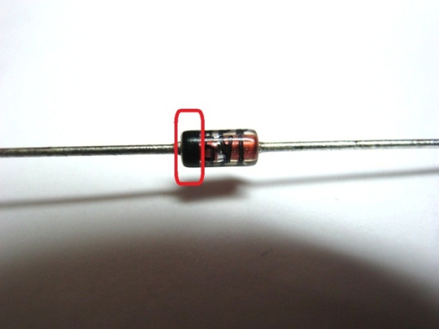
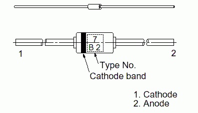
The photo below shows a classic version. Pay attention that directly on the case it is shown, where it has an anode and a cathode. A black (less common gray) strip is drawn around the circle, which is located on the side of the cathode. The opposite side is the anode. This method is used for both domestic and imported diodes.

Additional marking of glass models
Diodes in glass casings have their own designations, which we will consider below. They are so simple (unlike the options with plastic cases) that almost immediately memorized by heart, there is no need to use the directory every time.
Color marking is used for plastic diodes, for example, for SOT-23. The solid module housing has two flexible terminals. On the body itself, next to the strip described above, several numbers are added in the same color, separated by a Latin letter. Usually the record has the form 1V3, 9V0 and so on, the variety allows you to pick up any parameters by designation, as in SMD.
What does this code marking mean? It shows the stabilization voltage to which this element is calculated. For example, 1V3 shows us that this value is 1.3 V, the second option is 9 volts. Usually the larger the body itself, the greater the stabilizing property it possesses. The photo below shows a zener diode in a glass casing with a cathode labeling of 5.1 V
Conclusion
Correct selection of the zener diode parameters will allow obtaining a stable current, which is fed from the circuit to the circuit. Be sure to select such fuse parameters using the appropriate reference manual so that the input voltage does not spoil the part, it is desirable to stay approximately in the middle of the UCT ± ΔUCT range.
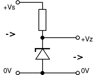
The zener diode is also called a reference diode. Zener diodes are designed to stabilize the output voltage when the input voltage fluctuates or when the load value changes ( fig. 1 ).
Fig. 1 - Functional diagram of the zener diode
For example, if you need to get 5 V on the load, and the power supply voltage fluctuates within 9 V. In order to reduce and stabilize the voltage supplied from the power supply, zener diodes are used up to the required 5 V. Of course, you can apply and voltage stabilizers, in this case, suitable or. However, their use is not always justified, so in some cases they use zener diodes.
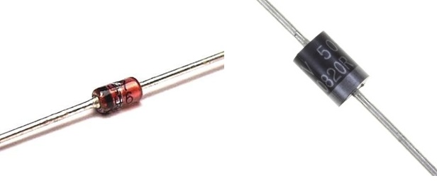
Outwardly, they are similar to diodes and have the form shown in fig. 2.
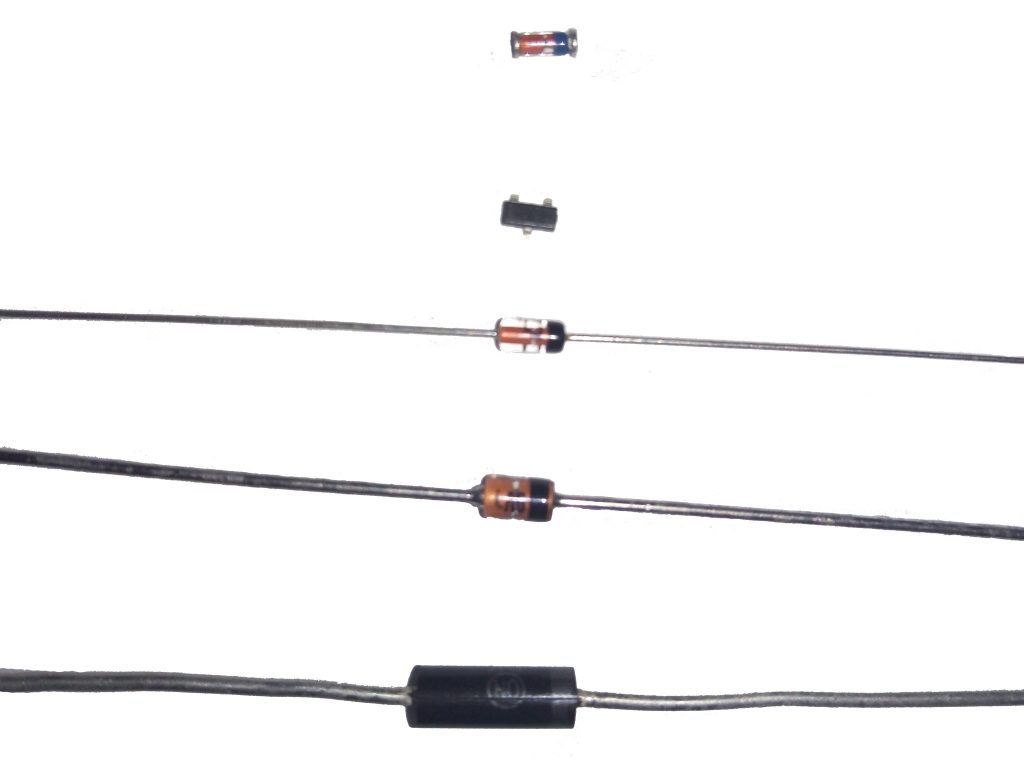
Fig. 2 - Appearance of zener diodes
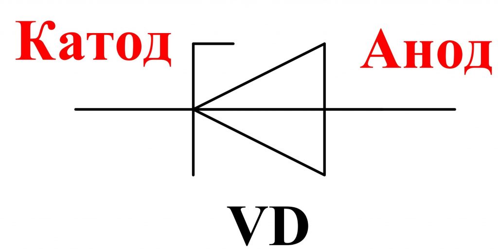
The designation of zener diodes on the diagrams is given in fig. 3 .
Principle of operation of a zener diode
Now let's look at how the zener diode performs voltage stabilization.
The main characteristic of a zener diode, however, like a diode, is the current-voltage characteristic (VAC). It shows the dependence of the current flowing through the zener diode on the magnitude of the applied voltage ( fig. 4).
The VAC of a zener diode has two branches.
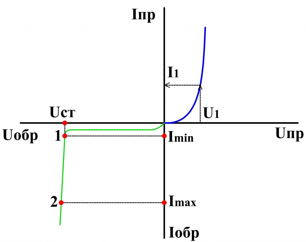
Fig. 4 - VAC of a zener diode
The direct branch of the zener diode does not practically differ from the straight branches of conventional diodes and for the latter it will also be a working one.
The normal mode of operation of a zener diode is when it is under reverse voltage. Therefore, the reverse branch will be working for him. It is located almost parallel to the axis of the reverse currents. There are two points on this curve: 1 and 2 (fig. 4), between them is the working area of the zener diode.
At a certain value of the reverse voltage U art. an electrical breakdown occurs p — n transition of a zener diode and through it already a considerable current flows. However, when the current varies widely from the value Imin before Imax voltage drop across a zener diode U art. practically does not change ( fig. 4 ). Due to this property, the voltage is stabilized.
If the current flowing through the zener diode exceeds the value Imax , then the semiconductor structure will overheat, there will be a thermal breakdown and the zener diode will fail.
To power supply Uip The zener diode is connected via a current-limiting resistor Roger , which serves to limit the current flowing through the zener diode, and also together with it forms a voltage divider ( fig. 5 ).
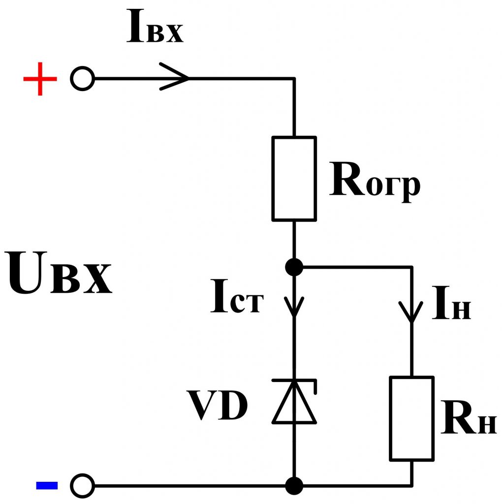
Fig. 5 - Zener diode connection circuit
Note, unlike the diode, the zener diode is connected in the reverse direction, ie, the "+" of the power supply is applied to the cathode, and "-" to the anode.
In parallel to the terminals of the zener diode, the load is connected R mr. , at the terminals of which it is required to maintain a stable voltage.
The process of stabilizing the voltage is as follows. As the voltage of the power supply increases, the total circuit current increases I , and hence the current Ist , flowing through a zener diode VD , and also the voltage drop on the current-limiting resistor increases R ogr . At the same time, the voltage on the zener diode and, accordingly, on the load remains almost unchanged.
When the load resistance is changed, the total current is redistributed I between the zener diode and the load, and the magnitude of the voltage on them practically does not change.
If the voltage across the load is greater than the stabilizing voltage of the zener diode, several zener diodes are connected in series. For example, if it is necessary to get 10 V of a stable voltage, then, in the absence of the required zener diode, it is possible to include in series two zener diodes of 5 V ( fig. 6th ).
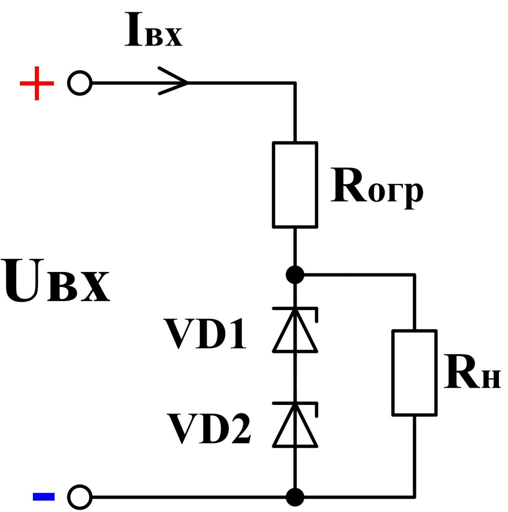
Fig. 6 - Serial connection of zener diodes
Also zener diodes are successfully used in automation systems as sensors reacting to voltage changes. For example, if the voltage exceeds a certain value, the zener diode opens and a current flows through the relay coil. As a result, the relay will work and give a command to other devices or simply signal about exceeding a certain voltage level.
In addition to stabilizing the DC voltage, stabilizers can also stabilize the AC voltage. To do this, use consecutive counter the inclusion of two zener diodes ( fig. 7th ).
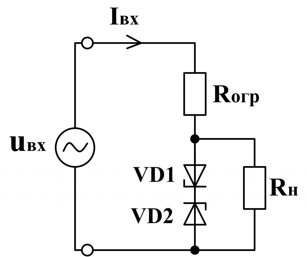
Fig. 7 - Scheme of zener diode on alternating voltage
Only the output will not be an ideal sine wave, but with cut off tops, i.e. the shape of the voltage will be approximated to the trapezium ( fig. 8, 9 ).
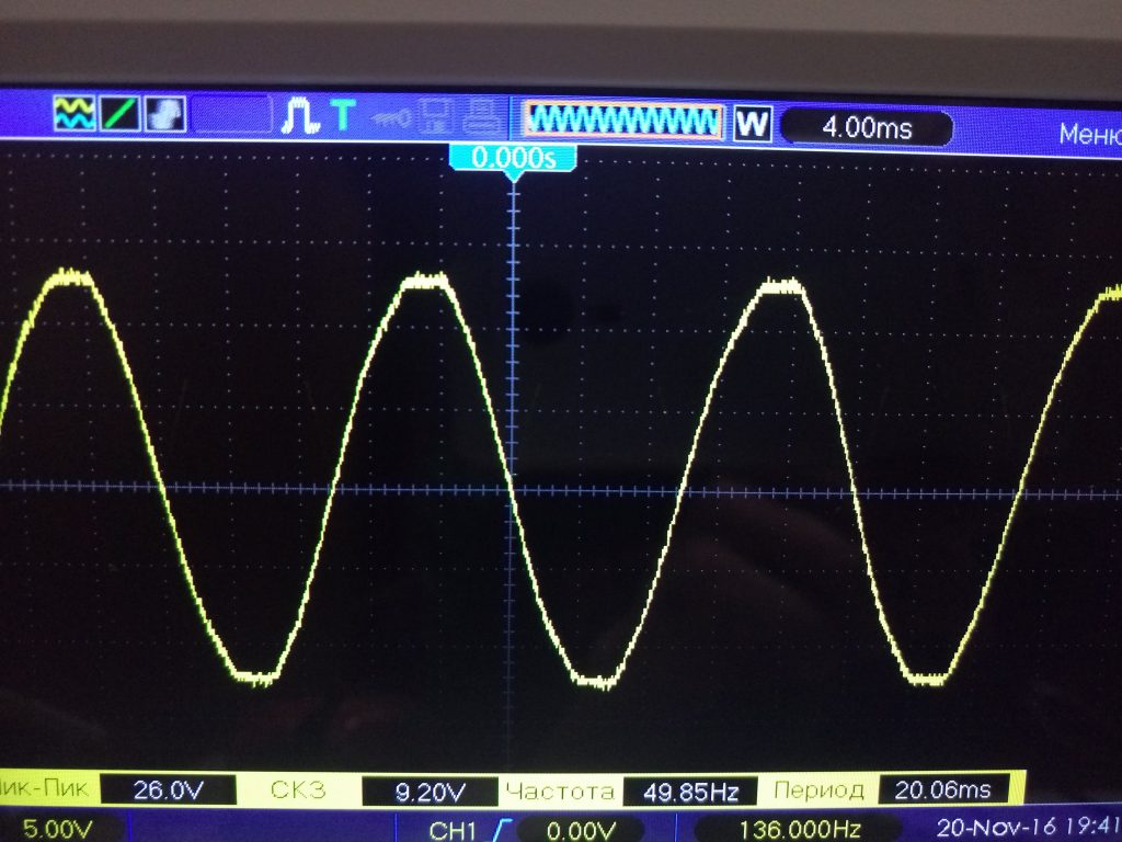
Fig. 8 - Oscillogram of the input voltage
![]()
Fig. 9 - Voltage oscillogram on the zener diode
Used several ways of marking zener diodes. Zener diodes in glass case, having flexible conclusions, are marked in the most understandable way. As a rule, figures are placed on the body, separated by the Latin letter "V". For example, 4 V 7 means that the stabilization voltage is 4.7 V; 9 V 1 - 9.1 V and so on ( fig. 10 ).
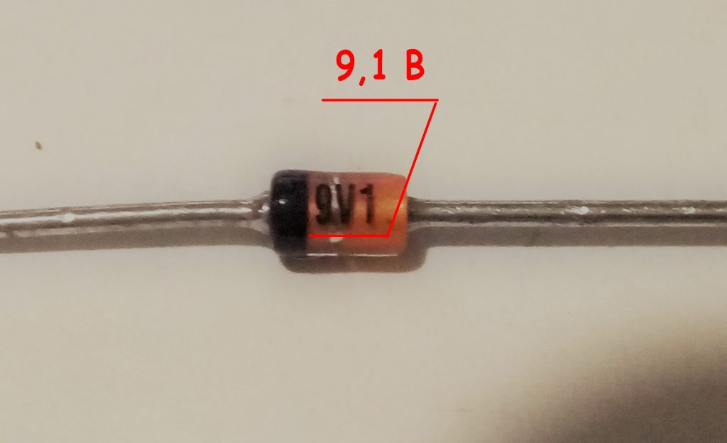
Fig. 10 - Marking of zener diodes in glass housings
Zener in the plastic case are marked in the form of numbers and letters. In themselves, these figures do not say anything, however, with the help of dashshit they can be easily decoded. For example, the designation 1N5349B means that the stabilization voltage is 12 V ( fig. eleven). In addition to voltage, this marking takes into account other parameters of the zener diode.
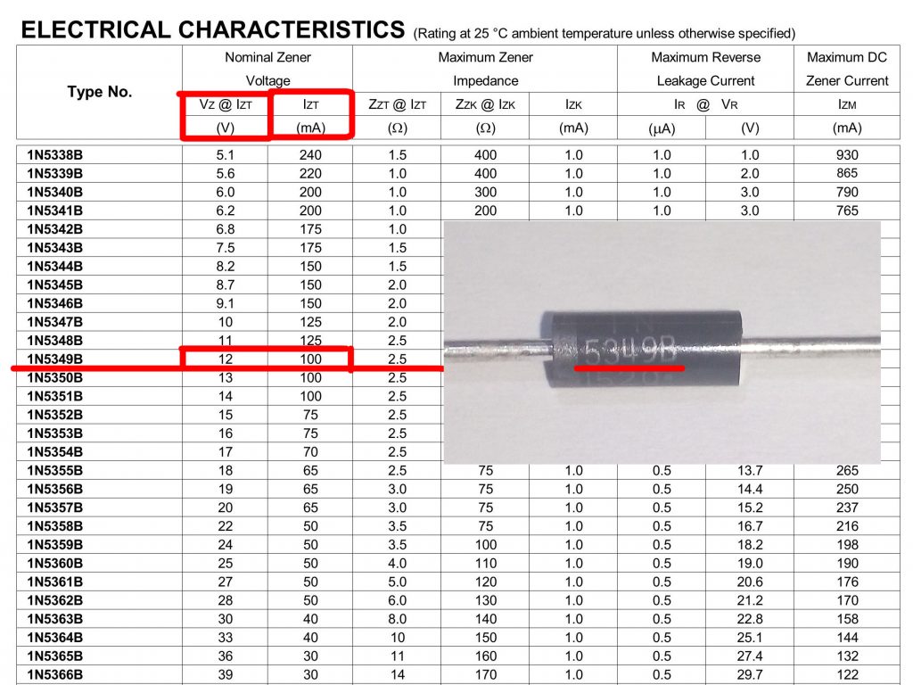
Fig. 10 - Marking of zener diodes in plastic housings
A black or gray ring applied to a zener diode body designates its cathode ( fig. 12 ).
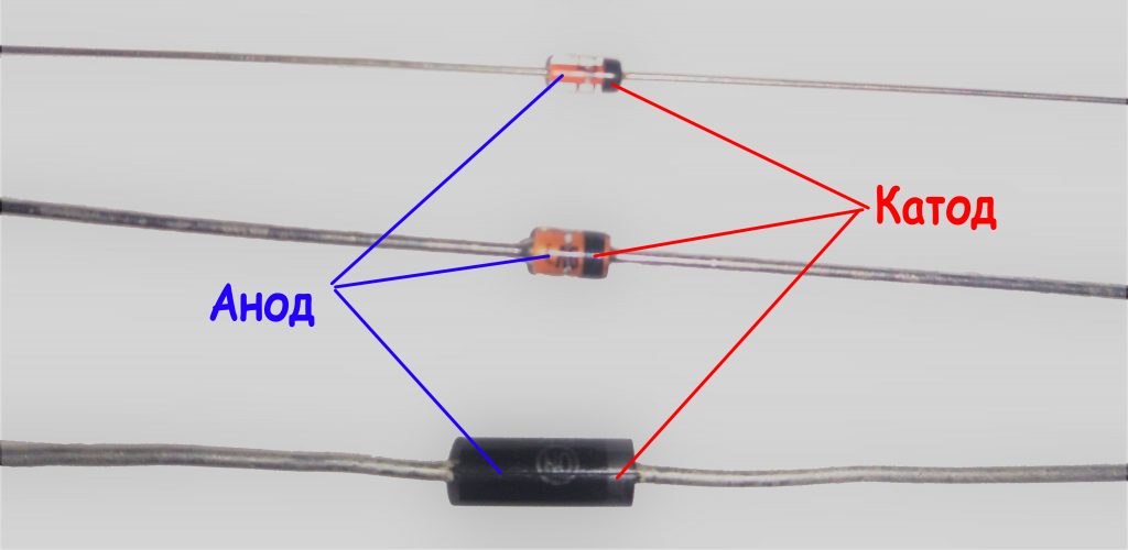
Fig. 12 -
Markingsmd zener diodes
As a marking of smd zener diodes, color rings are used. Similar markings are also applied for Soviet not smd zener diodes. In imported zener diodes, a colored ring is applied from the cathode side ( fig. 13 ). To decode colored rings, use dataschi or online decryption.
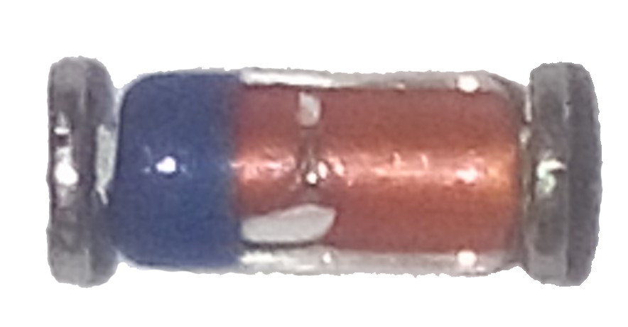
Fig. 13 -SMD zener diode in a glass case
Smd zener diodes with three pins are also manufactured ( fig. 14 ). One of them is not involved. These conclusions can be determined using a multimeter.
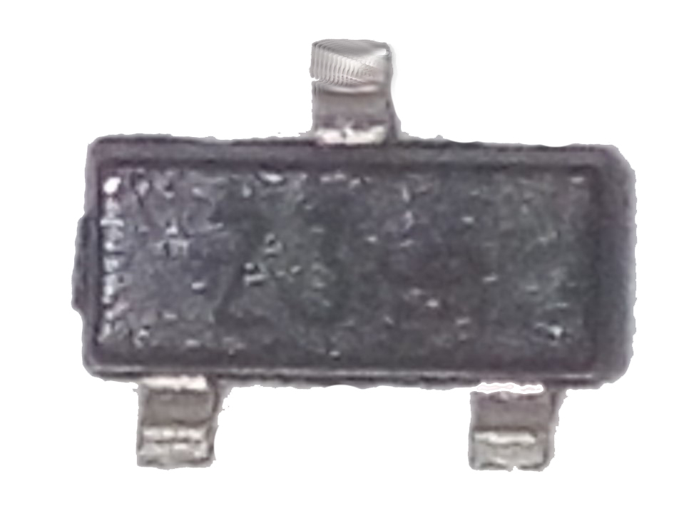
Fig. 14 - SMD zener diode with three leads
In the absence of a directory, a datasheet or fuzzy marking, the nominal voltage of a zener diode can be determined empirically. First, using a multimeter, you need to find out the corresponding conclusions and connect the zener diode via a current-limiting resistor ( see Fig. 5). Then apply voltage from the regulated power source. Smoothly changing the input voltage, you need to monitor the voltage change on the zener diode. If the voltage on the zener diode does not change when the voltage of the power supply changes, then this will be its stabilization voltage.
The conclusions of the zener diode are determined exactly as and. The multimeter should be set to the continuity mode and the probes should be touched by the probes ( fig. 15, 16 ).
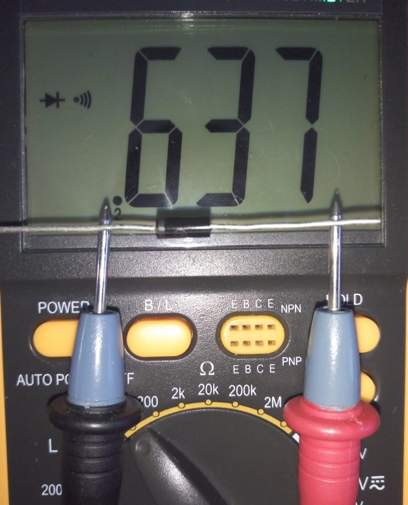
Fig. 15 - Direct voltage
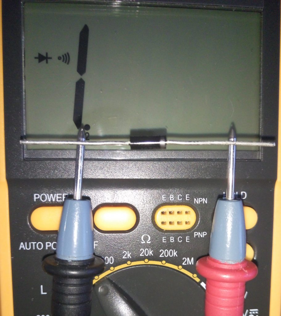
Fig. 16 - Reverse voltage
Under the action of a flowing current through the zener diode, it heats up. The released heat dissipates into the surrounding space. The more zener diode is able to dissipate heat without overheating, the higher its dissipation power and the more current can be passed through it. As a rule, the larger the zener diode dimensions, the greater its scattering power ( fig. 17th ).
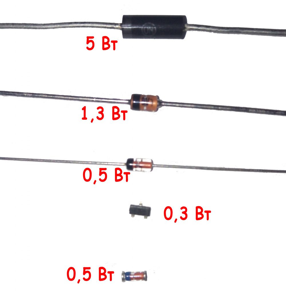
Fig. 17 - Power dissipation of zener diodes
Having a radio-electronic laboratory at home, you can make a variety of devices for your electrical equipment or the instruments yourself, which will save considerable money on the purchase of equipment. An important element of many electrical circuits devices is a zener diode.
Such an element (smd, cmd) is a necessary part of many electrical circuits. Due to its wide field of application, the zener diode has a different marking. The marking applied to the body of such a diode gives detailed but encrypted information about this element. Our today's article will help you to understand which color marking meets on the body (glass and no) of imported zener diodes.
What is this element of electrical circuits
Before we start to consider the question of what color marking of such elements exists, it is necessary to understand what it is all about.
Volt-ampere characteristic of a zener diode
The Zener diode is a semiconductor diode, which is intended to stabilize the DC voltage circuit in the circuit. Most often, such a diode is used to stabilize the voltage in various power supplies. This diode (smd) has a section with a reverse branch of the current-voltage characteristic, which is observed in the region of electric breakdown.
Having such a region, a zener diode in the situation of changing the current parameter flowing through the diode from ITS.MIN to ITS.MAKS practically no changes in the voltage index are observed. This effect is used to stabilize the voltage. In a situation where the RH load is connected in parallel to the cmd, then the diode voltage will remain constant, and within the specified limits the current flowing through the zener diode.
Note! Stabilitron (smd) is able to stabilize the voltage above 3.3 V.
In addition to CMD, there are also stability vectors that are included when direct inclusion. They are used in situations where there is a need to stabilize the voltage in a certain range. A conventional diode can be used when it is necessary to stabilize the voltage in the range from 0.3 to 0.5 V. The region of their direct displacement is observed when the voltage drops to 0.7-2v. In this case, it is practically independent of the current. Stabistors in their work apply a straight branch of the current-voltage characteristic.
They should also be included when direct connection. Although this will not be the best solution, since a zener diode in such a situation will still be more effective.
Stabistors, like smd, are often made from silicon.
The zener diodes are labeled according to their main characteristics. This marking has the following form:
- UDC. This marking means the nominal voltage for stabilization;
- ΔUst. Indicates deviation of the voltage indicator of the nominal stabilization voltage;
- Ist. Indicates a current that flows through the diode at a nominal stabilizing voltage;
- Ist.min - the minimum value of the current that flows through the zener diode. With this value, such an smd diode will have a voltage in the range UST ± ΔUST;
- Ist.MAX. Means the maximum permissible value of the current that can flow through the zener diode.
This marking is important when selecting an element for a specific wiring diagram.
Element designation
![]()
Schematic designation of a zener diode
Since the zener diode is a special diode, its designation does not differ from them. Schematically, smd is denoted as follows:
The zener diode, like the diode, has a cathode and anodic part in its composition. Because of this, there is a direct and reverse inclusion of this element.
Turning on the Zener diode
At first glance, the inclusion of such a diode is wrong, because it must be connected "on the contrary." In the situation of supplying reverse voltage to smd, the phenomenon of "breakdown" is observed. As a result, the voltage between its terminals remains unchanged. Therefore, it must be connected in series to the resistor in order to limit the current flowing through it, which will ensure the drop of the "excess" voltage from the rectifier.
Note! Each diode, designed to stabilize the voltage, has its voltage "breakdown" (stabilization), and also has its working current.
Due to the fact that each zener diode has such characteristics, it is possible to calculate the resistor value for it, which will be connected with it in series. For imported zener diodes, their stabilization voltage is represented in the form of a marking applied on the body (glass or not). The designation of such a smd diode always starts with BZY ... or BZX ..., and their breakdown voltage (stabilization) is marked V. For example, the designation 3V9 stands for 3.9 volts.
Note! The minimum voltage for stabilization of such elements is 2 V.
The principle of stabilization diodes
Despite the fact that the CMD is similar to a diode, it is in fact a different element of the electrical circuit. Of course, it can perform the function of a rectifier, but it is usually used to stabilize the voltage. This element is able to support in the circuit direct current constant pressure. This principle of its work is used in the supply of various radio equipment.
Externally, the CMD is very similar to the standard semiconductor. Similarity is preserved in structural features. But in the designation of such a radio-technical element, unlike a diode, the diagram puts the letter G.
If you do not delve into mathematical calculations and physical phenomena, then the principle of the functioning of smd will be fairly clear.
Note! When switching on such an smd diode, observe the reverse polarity. This means that the connection is made by the anode to the minus.
Passing through this element, a small voltage of the circuit provokes a strong current. With increasing reverse voltage, the current also increases, only in this case its growth will be observed weakly. Going to the mark, it can be any. It all depends on the type of device. When the mark is reached, a "breakdown" occurs. After the "breakdown" happened, a reverse current of large value begins to flow through smd. It is at this moment that the element begins to work until its permissible limit is exceeded.
How to distinguish a stabilization diode from a conventional semiconductor
Very often people ask how it is possible to distinguish a zener diode from a standard semiconductor, because, as we found out before, both these elements have almost identical designations on the electrical circuit and can perform similar functions.
The most simple way The difference between the stabilization semiconductor and the conventional one is the use of the preamplifier circuit to the multimeter. With its help it is possible not only to distinguish both elements from each other, but also to reveal the stabilization voltage, which is characteristic for a given cm (if it, of course, does not exceed 35V).
The circuit of the multimeter is a DC-DC converter, in which there is galvanic isolation between the input and output. This scheme has the following form:
![]()
The circuit of a prefix of a multimeter
The generator with pulse-width modulation is performed on a special microcircuit MC34063, and to create a galvanic isolation between the measuring part of the circuit and the power supply, the control voltage should be removed from the primary winding of the transformer. For this purpose, there is a rectifier on VD2. In this case, the value for the output voltage or the stabilizing current is set by selecting the resistor R3. On the capacitor C4, a voltage of about 40V is produced.
In this case, the tested VDX cm and the stabilizer for current A2 will form a parametric stabilizer. The multimeter connected to terminals X1 and X2 will measure the voltage on the zener diode.
When the cathode is connected to the "-" and the anode to the "+" diode, as well as to the asymmetrical cmd of the multimeter, the latter will show a slight voltage. If connected in reverse polarity (as in the diagram), then in the situation with a conventional semiconductor device will record a voltage of about 40V.
Note! For a symmetrical smd, the breakdown voltage will appear if there is any polarity of the connection.
Here, the transformer T1 will be wound on a torus-shaped ferrite core with an outer diameter of 23 mm. Such a winding 1 will contain 20 turns, and the second winding will have 35 turns of a PEV wire of 0.43. It is important when winding lay the turn to the turn. It should be remembered that the primary winding goes on one part of the ring, and the second - on the other.
When setting up the device, connect a resistor instead of smd VDX. This resistor must have a rating of 10 kΩ. And the resistance R3 should be selected in order to achieve a voltage of 40V on the capacitor C4
That's how you can find out whether you have a zener diode or an ordinary diode.
Details about the color marking of the stabilizing diode
Any diode (zener diode, etc.) on its body contains a special marking, which reflects what material was used to make each specific semiconductor. Such a marking can have the following form:
- letter or number;
- letter.
In addition, the marking reflects the electrical properties and purpose of the device. Usually the figure answers for this. The letter, in turn, reflects the corresponding version of the device. In addition, the marking contains the date of manufacture and symbol products.
ICDs of the integral type often contain a complete marking. In this situation, there is a conditional code on the case of the product, which indicates the type of the chip. An example of decoding of the code marking on the case for microcircuits is shown in the figure:
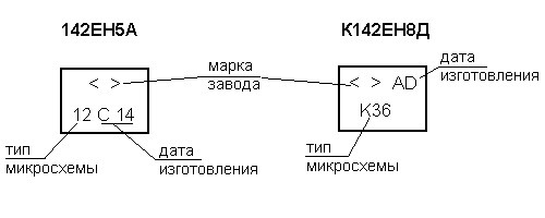
Example of chip labeling
In addition, there is also a color marking. It exists in several variants, but is most often used japanese marking (JIS-C-7012). Color markings are shown in the following table.
Color marking of the zener diode
- the first bar indicates the type of device;
- the second is a semiconductor;
- the third - what kind of device is it, and also what conductivity it has;
- the fourth is the development number;
- the fifth is the modification of the device.
It should be noted that the fourth and fifth strips are not very important for product selection.
Conclusion
As you can see, there are a lot of different markings and designations for the zener diode, which you need to remember when choosing it for a home laboratory and manufacturing your own electrical appliances. If you are good at this issue, then this is the key to the right choice.
How to choose a motion sensor for the toilet How to choose the right radio light switch with a remote control, how to connect