Antipyretics for children are prescribed by a pediatrician. But there are situations of emergency care for fever, when the child needs to give the medicine immediately. Then the parents take responsibility and apply antipyretic drugs. What is allowed to give to infants? How can you bring down the temperature in older children? Which medications are the safest?
PILOT_SVM 15-08-2016 14:33
There is an old power supply from the mobile (the so-called "charging").
The output is 5.25 V.
It is necessary to power it from the device, which operates on two AA batteries.
Is there an easy way to lower to 3 V?
PILOT_SVM 15-08-2016 14:40
Postoronnim V 15-08-2016 17:39
For example, a resistor. And if so, what resistance?
The resistor will extinguish up to three volts only under the condition direct current consumption.
But if the current consumption decreases - then the output will receive a voltage above three volts (in the future, the same 5.25 c.). And it's good if a three-voltage device can withstand this.
And to increase the current - the voltage will be lower than three volts (in perspective to zero).
The easiest way is to switch on a stabilizer, which can be replaced by a series of diodes.
Voltage drop on a silicon diode in the region of 0.6-0.8-1.0 volts.
3-4 diode, just lower 5.25 to three volts. Diodes take acc. the maximum current consumption of the three-voltage load.
Shl. Yes, forgot to say ..
Do not do it the way Dachnik_Miha suggested.
That circuit is a current stabilizer, not voltage.
With all the ensuing consequences of increasing the voltage at the final load, as in the case of a simple resistor.
unname22 16-08-2016 11:48
On one falls 0.7 volts roughly.
PILOT_SVM 16-08-2016 12:08
correctly suggested the diodes, only you need simple rectifying, not Schottky.
On one falls 0.7 volts roughly.
Mark tell pzhlsta!
Postoronnim V 16-08-2016 13:44
For household use, strength will be enough.
unname22 16-08-2016 13:56
PILOT_SVM
tell me in which store you will buy - from the range choose.
PILOT_SVM 19-08-2016 22:01
What is the current consumption for a three-voltage load?
Well, or at least tell me what the max. allowable current is indicated on the charger?
In principle, you can, of course, take whatever KD202 and their current margin is exactly enough, but, with knowledge of the max. current consumption load .. you can pick up diodes with less overall dimensions and without breaking your head where to put them .. take and simply solder them directly into the rupture of one of the supply wires .. yes insulate over.
For household use, strength will be enough.
But I will.
And probably easier to say that the consumer.
This is an electric motor.
Simplest.
In the network, he, the switch, has two batteries.
And moreover - the engine is completely oak and batteries (batteries) are consuming in 15-20 minutes. Obviously, this is not the most economical consumer.
And it seems to me that such a regime for accumulators is not the easiest.
So I want to do it on a network power supply.
Consumption current, I measure and report.
PILOT_SVM 19-08-2016 22:04
quote: Originally written by unname22:
PILOT_SVM
tell me in which store you will buy - from the range choose.
In St. Petersburg, many shops with electronics and electrical.
For sure, if you name two or three types of diodes (if you stopped on this option), then in one of the shops in St. Petersburg I will be able to find the right type.
But first I will determine the current.
I will inform you, and then it will be easier and more precise to choose the right one.
Postoronnim V 19-08-2016 22:36
quote: by PILOT_SVM:
The question of the consumer's current always strains me, because volts change easily (contacts threw on the conclusions and FSE), then the current should be measured by breaking the network (in series), and this should be something to fence.
Well, in the simplest tester there is a current measurement mode. Turn on the tester in this mode in series with the engine and learn the actual current consumption.
Only thus the engine should be loaded, since In idle mode, the current is always lower than under the workload of the motor.
If only one voltmeter is available, then turn on the resistor in series with the motor with a resistance of 1 ohm and the voltage on this resistor will be approximately equal to the current consumption.
By the way, on the chargers for a mobile phone, the permissible load current is usually written. Usually this is 0.5-1 A.
PILOT_SVM 19-08-2016 23:03
quote: Originally written by Postoronnim V:
1. Well, in the simplest tester there is a current measurement mode.2. Turn on the tester in this mode in series with the engine and learn the actual current consumption.
3. Only in this case the engine must be loaded; In idle mode, the current is always lower than under the workload of the motor.
4. If only one voltmeter is available, then turn on the resistor in series with the motor with a resistance of 1 ohm and the voltage on this resistor will be approximately equal to the current consumption.
Instead of a resistor, you can take a piece of thin wire with a resistance of 1 ohm. the truth for this will also need an ohmmeter.5. By the way, on chargers for mobile phones usually write the permissible load current. Usually this is 0.5-1 A.
2. That's exactly what I plan to do. Just for this you need to make a "sidebar".
3. In fact, the engine is not power, but rotates the impeller. So there is not much difference.
4. A multimeter is available.
Do not pull.
AZProtect 20-08-2016 01:28
quote: by PILOT_SVM:
It is necessary to power it from the device, which operates on two AA batteries.
quote: by PILOT_SVM:
And moreover - the engine is completely oak and batteries (batteries) are consuming in 15-20 minutes. Obviously, this is not the most economical consumer.
We assume an accumulator capacity of 1000 mA h (or 1 A h)
15 minutes is 1/4 hours.
If I do not confuse anything.
PILOT_SVM 20-08-2016 02:05
quote: Originally written AZProtect:
We assume an accumulator capacity of 1000 mAh (or 1 ac)
15 minutes is 1/4 hours.
Total consumption is about 4 amperes maximum.
At 3 volts, this motor is somewhere in watts at 12.
If I do not confuse anything.p.s. in other words, the line ~ 8 watts of heat must be scattered on the diodes.
In these calculations, I'm not strong.
The accumulators are 2700 mA.
Postoronnim V 20-08-2016 06:46
quote: by PILOT_SVM:
And the insertion of a resistor 1 Mom into the network - it gave such a drop that the engine did not pull.
First showed - 2 V, then 1 V in general.
Do not pull.5. On charging it is written - 4.9 V and 450 mA.
Of course there will be a drop equal to almost all of the voltage
Because 1 MΩ is a million times larger than 1 Ohm.
If 450 mA is written on the charger, then the diodes need to be searched for current not higher. On strength with a margin of 20%.
Because when the current is exceeded, the charger will burn, and not the diodes.
On the other hand, if the motor operates as a fan drive, its current consumption can be considered constant and a simple resistor suffices.
But to calculate the resistance and dissipated power of this resistor, you still need to know the current consumption of the motor.
quote: by PILOT_SVM:
In these calculations, I'm not strong.
The accumulators are 2700 mA.But in the process of working clearly - about 15 minutes the engine buzzes strongly, and then noticeably sags.
And as far as I can remember - for a nickel-metal hydride battery, a fast discharge is undesirable.
Judging by what you are telling, the 450mA charger simply will not pull.
Measure the current consumption from the batteries.
On a conventional multi-tester, there is a separate socket for measuring ampere currents (10A)
Here is one probe left in the "ground" slot, the second one into the 10A socket, select the 10A mode switch and connect the probes to the motor power circuit in series.
In this case, it would be nice to monitor the voltage on the batteries with the second tester. if the batteries are half-alive, then this voltage can become dull, and we need to know its value for the calculation of a resistor or a diode.
RTDS 20-08-2016 08:46
Already schemes nagorodili .....
Turn on the motor to start directly to the charger, to 5 volts.
It is likely that the voltage will subprocess to the required - 3.4-4.5 volts your motor is not overloaded, the more so that it also rotates the impeller ....
unname22 20-08-2016 14:03
Just go to the store and say, you need a 5 Amp diode with a voltage of 50 volts to infinity, but not Schottky, will pick up easily.
hunter1957 21-08-2016 22:08
quote: The question of the current of the consumer always strains me, because volts change easily (contacts threw on the pins and fso), then the current should be measured by breaking the network (in series), and this should be something gorodit.No I'll do. And it's probably easier to say that for the consumer. This electric motor. The simplest. network it, the switch, two batteries. And moreover - the engine is completely oak and batteries (batteries) are consuming in 15-20 minutes. Obviously, this is not the most economical consumer. And it seems to me that such a mode for accumulators is not the easiest. That's what I want to do on a network power supply. I measure the consumption and report it.
quote: In these calculations, I'm not strong. The Akkums are 2700 mA. But in the course of the operation it's obvious - about 15 minutes the engine is humming heavily, and then noticeably settles. And as far as I can remember, a fast discharge is undesirable for nickel-metal hydride batteries.
From the initial data emerges: Power source two metal-hydride batteries with a nominal capacity of 2.7A / H. The voltage of the fully charged batteries is 2.4 volts. The final voltage for them is 1 volt per 1 cell. For a quarter of an hour the batteries sit down .... The actual discharge current is about 10 amps, the power supply must also be taken into account that the starting short-time consumed current will be on the order of 2-3 times more .... Your charging of 5 volts is unsuitable - it does not give the required current ...
From available mass sources of power, the impulse power supply of a computer of the ATX standard is practically unchanged - there is an output of 3.3 volts 10 amperes.
alexaa1 22-08-2016 06:01
Something tells me that it's something like cutting off the spools-there's no big ampere there-at most one ampere.
PILOT_SVM 22-08-2016 09:35
Metering showed:
PILOT_SVM 22-08-2016 09:36
quote: Originally written by alexaa1:
Something tells me that something like cutting a spool
Yes exactly.
hunter1957 22-08-2016 10:10
quote: Metering showed:You have measured the prices for oats .... Apparently the batteries have lost the capacity. According to the correct current, you need to measure at the limit of 10 amperes and use high-quality alkaline batteries ... In reality starting current short-term for such motors 5-10 amperes, working more than 3 amps .... Go to the computer programmers - set the task to connect the motor to 3.3 volts and you will be happy. The wire for connecting to the motor is not less than 0.75 mm2.
The scale of current measurements is 200 microamperes, 2000 microamperes, 20 milliamperes, 200 milliamperes.
The next value is 10 A, and the contact must be rearranged.
On the scale of the multitesters, 200 mA (max) were set - at the same time, first (without load), the display popped up 3-4.5 then smoothly moved down to 1 - 1.2.
With a small load - began to skip 2, 3 and 4.8.
The truth sometimes jumped and more, but for a short time.
On the motor - there are no markings other than "-" and "+" and arrows (if we assume that this direction of rotation with just such a connection of plus and minus.
And - I looked at the direction of the movement - for some reason the contacts are confused.
What would it mean - I'm not clear.
PILOT_SVM 22-08-2016 11:47
quote: On the correct current, you need to measure at the limit of 10 amperes and use high-quality alkaline batteries
At 10 A - in general and does not show and does not work.
The new ones are 2700 mA.
So your numbers are clearly overstated.
hunter1957 22-08-2016 12:09
quote: At 10 A - in general and does not show and does not work. The new ones are 2700 mA. So your numbers are clearly overstated.How do you charge the batteries? proper charging from Lacrosse - it allows you to accurately measure the actual capacity of the battery, train and restore ... A new battery fresh can have a real capacity of 0.5a / h. Do you have a defective device or you just do not know how to use it. U AA / AAA batteries 1.5 volts the operating and internal resistance is less than the battery. With electronics for you for half a century .... The current is measured only when connected in series ... Try if your device is working correctly on the resistance measurement to measure the resistance engine at a plurality of positions of the rotor ....
PILOT_SVM 22-08-2016 13:14
quote: What do you charge the batteries? I have the correct charge from Lacrosse
Charging GP, and the same brand of batteries.
quote: AA / AAA batteries have a voltage of 1.5 volts operating and internal resistance is less than the battery
The batteries - 1.5 V, and the batteries - 1.3 V.
When measuring naprugi and current - the tester did not show, and when measuring resistance - showed a weak battery.
I'll buy a battery - I'll repeat the resistance measurements.
hunter1957 22-08-2016 13:40
quote: Charging GP, and the same brand of batteries.
Charging by and large the simplest budget, it kills batteries quite quickly .... The batteries of GP IMHO I never came across decent ...
PILOT_SVM 22-08-2016 16:13
Charging by and large the simplest budget, it kills batteries quite quickly .... The batteries of GP IMHO I never came across decent ...
And what does "quickly kill"?
On charging it is written:
for AA batteries:
If charging 4 pieces, then at a voltage of 2.8 V is given by 525 mA.
If charging 2 pieces, then at 2.8 V, - at 1050 mA.
What is wrong?
Wrong mA?
Need more? Need less?
Need variable charging mode?
The previous set of batteries (2500 mA) worked for 4 years.
Few?
Are your batteries serving 10 years?
hunter1957 22-08-2016 17:05
quote: On charging it is written: for AA batteries: If charging 4 pieces, then at 2.8 V voltage is given for 525 mA. If on charging 2 pieces, then at 2.8 V, - at 1050 mA. What is wrong? Wrong MA? You need more? Need an alternate charging mode? Previous set of batteries (2500 mA) worked for 4 years. Is it too small? Your batteries serve 10 years?My son in the last century, the player was powered by GPU accumulators - it lasted a little more than a year .... For all manuals, the standard charge mode is 0.1 of full capacity for 14 hours, a discharge of no more than 0.1 capacitance for 10 hours or up to 1 volt. The declared resource of 500 cycles of charge - discharge .... I have thanks to Lacrosse are still working finger batteries Soviet ZNK-0.45 on estimates already 800 cycles worked .... GP started immediately the capacity to lose and after 50 cycles charge-discharge brand charge they have less than 15% of the claimed capacity .... A computer power supply is guaranteed without rework will ensure 100% performance of your gadget ....
PILOT_SVM 22-08-2016 18:49
quote: For all manuals, the standard charge mode is 0.1 of full capacity for 14 hours
Usually on the batteries themselves they write - 0,1 from the capacity for 16 hours.
quote: The stated resource of 500 cycles of charge - discharge .... I have thanks to Lacrosse still working finger batteries Soviet ZNK-0.45 on estimates already 800 cycles worked
As I said, the 2500 mAh batteries served for 4 years. Especially tense in the summer. I think there are at least 500 cycles.
By the way - earlier, for the nickel-metahydr of the accumulators, all claimed 1000 cycles.
Now for some reason 500.
By the way about the stamps - very much hoped for the accumulators VART,
but they served no more than a GP.
By the way - you said that you need a power supply and wires 0.75 mm2.
And in fact there wiring is approximately like a thread? 20.
But in general about the batteries everything is clear.
They work for me and this is normal.
I would sort out the power supply of the motor.
And here, the parameters you stated, seem excessive to me.
hunter1957 22-08-2016 20:02
quote: Speaking of brands, I was hoping for a battery of VART, but they served no more than a GP. By the way, you said that you need a power supply and wires 0.75 mm2. And in fact, there wiring is approximately like a thread? 20. But in general about the battery everything is understandable. They work for me and with this everything is normal. I should understand the power of the motor. And here, the parameters you stated, they seem excessive to me.And Warta and GP, and many more brands are producing in China, not only of different quality and different purposes and different selling prices ... Our barges are trying to take the most budgetary, for Western Europe and the USA their barges are buying more expensive and qualitative. power - the stock is not superfluous - just 10 amperes maximum current in the specification. The wire on the specification if I'm not mistaken should be? 18 or? 20 - good brands in premium power supplies can have a thicker wire ....
PILOT_SVM 28-08-2016 19:54
but it is possible to connect the light bulb to 1.5 V?
hunter1957 29-08-2016 12:15
quote: but it is possible to connect the light bulb to 1.5 V?
There is no sense - the resistance of 1.5V lamps is too high ....
There is no alternative to a computer BS for you, a universal laboratory power unit costs at least an order of magnitude more ... If it scares that from 3.3 volts the machine will break to be switched in series in forward direction a powerful silicon diode for 10 amperes - such as Soviet D242 / 246, when the diode is turned on reverse diode polarity circuit will simply not work. The voltage drop across the diode is 0.7-1.5 volts depending on the current and the lettering in the marking.
PILOT_SVM 17-09-2016 20:25
Another issue on charging.
Dismantled the broken charge.
The reason is most likely in the burned transistor, from it flew a piece of shell.
And in passing I saw that on the board are drawn 4 diode, which most likely should make up a diode bridge, but ...
There is only one diode, and three simply do not.
And the diode is not after the transformer, but immediately after the contact at 220 V.
A diode with a size of 6-7 mm in length, a diameter of -2-2.5 mm.
Is there really such a Lilliputian detail on 220 V?
I have diodes designed for 220 - they are very large and the contacts are there under the nuts.
hunter1957 17-09-2016 20:35
quote: Another issue on the charge. I disassembled the broken charge. The reason is most likely in the burned transistor, a piece of the case flew away from it. And incidentally I saw that there are 4 diode on the board, which most likely should make up a diode bridge, but ... It is only one diode, and three just net.Prichem diode is not after the transformer, and immediately after the contact at 220 V. Diode size - the length of 6-7 mm, diam -2-2.5 mm.Neucheva at 220 V are these Lilliputian details? I have diodes designed for 220 - they are very large and the contacts are there under the nuts.
Switching power supply.
The size does not depend on the voltage, the size depends on the rectified current and the dissipated power.
PILOT_SVM 18-09-2016 13:25
quote: Originally written by hunter1957:
Switching power supply.
The size does not depend on the voltage, the size depends on the rectified current and the dissipated power.
I have a sense that you are a person in the subject.
But it's difficult to understand you.
Perhaps this is inherent in all specialists.
hunter1957 19-09-2016 01:04
quote: I have a sense that you are a person in the subject. But to understand you is difficult. Probably it is inherent in all specialists.
If there is a desire to penetrate there is a wonderful two-volume / three-volume Horowitz and Hill "The art of circuitry" where it is very easily explained what works. The power units are devoted to the head - the volume of the chapter is small and practical schemes and their calculation are given ....
PILOT_SVM 19-09-2016 09:32
quote: Originally written by hunter1957:
If there is a desire to penetrate there is a wonderful two-volume / three-volume Horowitz and Hill "The art of circuitry" where it is very easily explained what works. The power units are devoted to the head - the volume of the chapter is small and practical schemes and their calculation are given ....
At the moment - I'm 6 simpler, like "click on the button, get the result."
Like the sounded earlier advice - to put a diode.
hunter1957 20-09-2016 02:15
quote: At the moment - I'm 6 simpler, like "click on the button, get the result." Like the previous advice - to put a diode.Everything is not so easy in your case - different diodes, different voltages and currents and with different voltage drops with different currents .... Read the book at least for general development and understanding of the processes, the book is written plain language affordable ......
Postoronnim V 20-09-2016 08:54
Although already explained several times higher, but I repeat:
In this case, you need to know the maximum current consumption of the powered device. (hereinafter referred to as "I").
Next, we look for diodes designed to work at this current.
This parameter of the diode is called I Ave max. (There is also I pr max pulse - but in this case it is not necessary to navigate it).
Here you choose diodes with I pr. Max. not less than one and a half I cons. Max.
Next, look at a diode parameter, such as a direct voltage on an open diode - U pr.
For different types of diodes, this parameter is different. From small voltages (Schottky diodes, germanium diodes) to several volts (thyristors, LEDs, stabilizers).
In this case, the most common silicon rectifier diodes are enough.
For conventional silicon rectifier diodes, U pr in the region of 0.5-1.0 volts. (with a spread of 0.1-0.3 volts can even be on the same type of diodes .. and on different direct currents).
Here, look at the passport U pr .. buy diodes for 2-3 pieces more, connect them in series, connect the load, monitor the voltage with a voltmeter. if it is slightly less than required - exclude (interconnect) one diode. The voltage on the load will increase by the amount of the drop of the U pr on the diode that is specifically disconnected.
Will be small - exclude the next diode.
Etc. until the desired result is achieved.
Shl. Of the most important parameters of the diode, there is also the maximum allowable reverse voltage, but in this case it can be ignored; 5-10 volts reverse will stand almost any rectifying diode, and here their back-admissible also will be added.
PILOT_SVM 20-09-2016 11:29
PILOT_SVM 20-09-2016 17:16
If possible - tell me, can I make an addition from these parts to reduce the voltage? 
hunter1957 20-09-2016 18:34
quote: If possible - tell me, can I make an addition from these parts to reduce the voltage?
Six elements located for 3 hours with a very high probability of a diodes, check for serviceability with a multimeter will take one minute.
The photo can not reliably determine the brand - I'm not a magician .... Wanggu that even if these diodes are in service - they are very likely not able to work because of exceeding the permissible maximum current ..........
PILOT_SVM 21-09-2016 20:55
There diodes: 5 scht. IN4007.
1 piece - DB 3 bufan
hunter1957 21-09-2016 21:25
quote: There diodes: 5 scht. IN4007.1 pcs. - DB 3 bufan
These parts are not suitable, I justify: IN4007 has a maximum current of 1 ampere - if it is exceeded, it will simply fail - the starting current of your toy is much more than 1 ampere ...... DB 3 - is not a diode - it is a dynistor and it by definition not suitable ....
PILOT_SVM 21-09-2016 22:33
A resistors can something be corrected?
hunter1957 22-09-2016 08:55
quote: A resistors can something be corrected?
These are not present ..... Here resistors are necessary with much greater capacity of dispersion and resistance less than 1 Ohm - they are very rare, have the big dimensions and cost sometimes decent money.
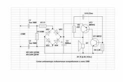
Attention novelty! Voltage stabilizer for the whole house SKAT ST-12345 Designed specifically for networks with low and very low mains voltage. It uses the voltage-boosting principle of raising the voltage. It raises the voltage from 125 Volts! Has a high power of 12 kVA! Warranty - 5 years! Test video of the stabilizer see.
Low and low voltage. Causes
Why it is well known in our electrical networks. The main reasons are aging electrical networks, poor maintenance, wear of the main equipment, incorrect network planning, a significant increase in energy consumption. As a result, we have millions of consumers receiving low voltage. Well, if the network parameters drop to 200 volts, it often happens that in homes 180, 160 and even 140 volts.
As you know, the voltage in the network is not the same for consumers connected to the same transmission line. The further the consumer is from the switchgear, the lower will be its value. Of course in this situation it is necessary increase the voltage.
To lower voltage also leads to a significant increase in the power of each consumer in the network. Now it is difficult to find a house in which there is only one kettle, one TV, one refrigerator and five light bulbs. But this is an approximate calculation of electricity consumption in the Soviet years, while in homes installed machines (plugs) at 6.5 amperes. Not a complicated calculation of 6.5 x 220 shows that maximum power of electrical appliances connected simultaneously did not exceed 1.5 kW. Today one good kettle takes 2 kW. As a result, the network sags, we get a low voltage.
Another phenomenon of modern life, which leads to a decrease in the current parameters is the seasonality and periodicity of the increase in the load. Especially good this phenomenon can be traced in the country villages.
In summer, consumption is increasing: summer residents come, water, build, boil, soar, cool, pump, watch, ventilate, drill, saw, mow, mark, eat, eat - well, generally "consume". And in winter there is no one - it's cold and boring. As a result, in the summer, the stress decreases, and in winter it increases.
On weekends, summer residents come, water, build, cook, soar, cool, pump, watch, ventilate, drill, saw, mow, mark, eat, eat - well, they "consume" again. And on working days there is no one - quiet and boring. As a result, during the weekend, the voltage drops, but it grows in the workers.
What is dangerous is low and low voltage
The electrical devices we use are designed for input voltage in the range of 220-230 volts plus or minus 5%. Proceeding from this, all the electrical parameters of the devices are determined: the total resistance, the resistance of individual parts of the circuit, the length and cross-section of all conductors, the number of turns in the windings of motors and electromagnets, the parameters of transistors, resistors, capacitors, transformers, heating elements.
If the network low or undervoltage
, then electrical appliances may not work correctly, not efficiently or not at all. Low Voltage may lead to a malfunction of the device, overheating, additional wear or even fire of the device. This is why it is necessary increase tension.

Which devices are sensitive to this problem, and which ones are not?
Easily carry undervoltage lighting: incandescent bulbs will work, but the light will give more dim. Electric stoves will also work, but less efficiently. Easily carry low voltage modern TVs equipped with pulsed sources power supply with a wide range of input voltage.
The most sensitive to low voltage motors, electromagnets, control boards.
Low voltage leads to a significant (multiple) increase in the load on the windings of electric motors. The lower the voltage, the greater the current in these devices. As a result, the wires can overheat and even melt, the device will burn. That's why refrigerators and pumps can not even turn on at low voltage, from full combustion they are saved by built-in protection, disconnecting the device. For normal operation of the motors, it is necessary to increase the voltage.
Low voltage is dangerous for electronic control elements of various complex devices. When the voltage is low, the chips and processors do not work correctly, which leads to the disconnection of the device or its failure. It is impossible to operate modern heating columns at low voltage, they have both electronic control and electric pumps. For normal operation electronic devices it is necessary to increase the voltage.
How to increase the voltage in the network
To increase the voltage in the network there are two main ways. The first is to get the power engineers to normalize the parameters of electric power. Write complaints, go to receptions to the authorities, conduct examinations, go to court. The method is correct, but very difficult.
The second way to increase tension is to use modern stabilizers. Of course, this method does not always work, if the voltage is very low (less than 120 volts), then this method does not work.
If you decide to use stabilizers to increase the voltage in your home, you need to determine the current parameters and the magnitude of the load. Based on these parameters, choose a stabilizer.
You can install one powerful stabilizer at the entrance to the house and ensure the normalization of the current parameters in all rooms. This method is the most effective, but it requires investment of funds, professional installation, special premises.
You can install several local small stabilizers in the most important places.
This method is more simple and less expensive. First of all, it is necessary to increase the voltage to normal for such consumers as: pumps, refrigerators, air conditioners, gas columns.
Increase the voltage with the help of stabilizersSkatandTeplocom
A large selection of reliable stabilizers Skat and Teplocom you can find in the section "Surge Protectors" . The high quality of the Skat and Teplocom voltage regulators is guaranteed by 20 years of experience in the production of electrical equipment.
The plant has introduced, maintained and effectively operates a quality management system based on the principles of the standard ISO 9001. All products of the company complies with the requirements of ISO 14001 and OHSAS 18001.
Voltage stabilizers are recommended by the specialists of companies: Vaillant, Baxi, Junkers, Thermona, Bosch, Buderus, Alphatherm, Gazeco, Termet, Chaffoteaux, Sime.
A reliable factory warranty is 5 years!
How to reduce the voltage on the transformer.
Hello colleagues!
In this article I will tell you how from transformer with a 32 V output, make transformer with an output of 12 V. In other words - reduce the voltage of the transformer.
For example, take a trance from the Chinese b / w TV "Jinlipu".
I think a lot of people met him or her.
So first we need to determine the primary and secondary windings. To do this, you need a regular ohmmeter. We measure the resistance at the terminals of the transformer. On primary winding resistance is greater than secondary and is, as a rule, not less than 85 Ohm.
After we have identified these windings, we can proceed with the analysis of the transformer. It is necessary to separate the Sh-shaped plates from each other. To do this, we need some tools, namely: round nose pliers, pliers, a small screwdriver for "podtsepa" plates, nippers, knife.
To get the very first record, you'll have to work hard, but then the rest will go like clockwork. You need to work very carefully, because you can easily cut yourself on the plate. Specifically, on this transformer, we know that it has an output of 32 V. In the case where we do not know this, we must measure the voltage before parsing, so that in the future we can calculate how many turns are going to 1 V.
So, let's start the analysis. With a knife you need to peel off the plates from each other and, with the help of nippers and round-nosed pliers, pull them out of the transformer. This is how it looks:

After the plates have been removed, it is necessary to remove them from the windings plastic housing. We do this boldly, since it will not affect the operation of the transformer in any way.


Then we find on the secondary winding the contact available for unwinding, and we "bite" it off from the place of adhesion by the cutters. Next, we begin to unwind the winding, while always counting the number of turns. So that the wire does not interfere, it can be wound on a ruler or something like that. Since on this transformer on the secondary winding 3 pins (two extreme and one middle), it is logical to assume that the voltage at the middle pin equals 16V, exactly half of 32V. Unwind the winding until the middle contact, i.e. to half, and count the number of turns that we unwound. (If the transformer has two leads on the secondary winding, then unwind it "by eye" to half, count the turns in this case, then cut the unwound wire, clean its end, solder it back to the contact and collect the transformer, doing everything the same as when disassembling, only in the reverse order.Then, we again need to measure the voltage that we got after reducing the turns and calculate how many turns are in 1. We calculate this: suppose you had a transformer with a voltage of 35 V. After you unwound about half the transformer was reassembled, you had 18 V. The number of turns that you unwrapped is 105. That means that there are 105 turns in 17V (35V-18V = 17V), which means that there are approximately 6.1 turns on 1V (105/17 = 6,176) Now, in order to reduce the voltage by another 6V (18V-12V = 6V), you need to unwind about 36.6 turns (6.1 * 6 = 36.6) .This figure can be rounded to 37. To do this you need to again disassemble the transformer and do this "procedure".). In our case, reaching half the winding, we got 106 turns. So these 106 turns are at 16V. Calculate how many turns it takes to 1V (106/16 = 6,625) and unwind about another 26.5 turns (16V-12V = 4V; 4V * 6.625 turns = 26.5 turns). Then we "bite off" the unwound wire, clean it from the varnish, tin it and solder it to the contact on the transformer, from which it was "bitten off."


Now we assemble the transformer in the same way as we disassembled, only in the reverse order. Do not worry if you have one or two records, the main thing is that they are very tightly "sat." That's what should happen:

It remains to measure the voltage, which we got:

Congratulations, colleagues, everything turned out perfectly!
If something does not work out the first time, do not be discouraged and do not give up. Only by showing tenacity and patience, one can learn something. If you have any questions, leave them in the comments and I will answer them.
In the next article, I'll tell you how to make a 12V DC power supply from this transformer.