Antipyretics for children are prescribed by a pediatrician. But there are situations of emergency care for fever, when the child needs to give the medicine immediately. Then the parents take responsibility and apply antipyretic drugs. What is allowed to give to infants? How can you bring down the temperature in older children? Which medications are the safest?
Winding group
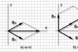
When constructing the vector diagrams of the transformer, it was considered that the phase winding of the VN winding Ė AH and windings HH Ė ahcoincide in phase. But this is true only under the condition of winding the primary and secondary windings of the transformer in one direction and with the same labeling of the leads of these windings, Fig. 46, a. If, however, in the transformer to change the direction of the winding of the LV or to rearrange the designations of its terminals, the EMF Ė ah will be shifted in phase relative to emf Ė AH by 180 ° (Figure 46, b) . Phase shift between EMF Ė AH and Ė ah it is customary to express a join group. Since this phase shift can vary from 0 to 360 °, and the multiplicity of the shift is 30 °, a number of numbers are taken to designate the compound group: 1, 2, 3, 4, 5, 6, 7, 8, 9, 10, 11 and 0.
The angle of displacement of the vector of the linear EMF of the winding HH with respect to the vector of the linear EMF of the winding VN is determined by multiplying the number designating the connection group by 30 °. The offset angle is counted from the EMF winding EM clockwise to the EMF winding vector. For example, the group of compound 5 indicates that the EM electromotive force vector is lagging behind the BH EMF vector by an angle of 5 × 30 ° = 150 °.
For a better understanding of the accepted designation of groups, the compounds are compared with the clock. In this case, the EMF winding EM vector corresponds to the minute hand, set on the digit 12, and the EMF vector of the winding HH is clockwise (Fig. 47). It is also necessary to bear in mind that the coincidence in phase of the EMF vectors Ė AHand Ė ahequivalent to the coincidence of the clock hands on the dial, is denoted by the group 0 (not 12). In addition, it should be remembered that the positive direction of rotation of the EMF vectors is their rotation counterclockwise.
Thus, in a single-phase transformer only two connection groups are possible: the group 0 corresponding to the coincidence in phase Ė AHand Ė ah, and group 6 corresponding to a phase shift between Ė AHand Ė ahby 180 °. Of these groups, GOST only provides the group 0, it is denoted by I / I - 0.
By using different methods of connecting windings in three-phase transformers, 12 different connection groups can be created. Consider, for example, the star-star connection scheme (Figures 48, a). Vector EMF diagrams show that the shift between linear emfs Ė ABand Ė ab in this case is zero. This can be verified by combining points A and a when superimposed vector diagrams of the EMF windings of HV and LV. Consequently, for the indicated winding connection schemes, group 0 takes place; is denoted by Y / Y - 0. If on the LV side to the zero point connect the clamps a, b and from, and remove the EMF from the clamps x, the and z, then the EMF Ė ab will change the phase by 180 ° and the transformer will belong to group 6 (Y / Y - 6) (Figure 48, b).
Fig. 46. Winding groups of single-phase transformers:
a- group I / I - 0; b- Group I / I - 6

Fig. 47. Comparison of the position of the hands of the clock with the designation of connection groups
When connecting the star-delta windings shown in Fig. 49, a, the group 11 (Y / D-11) takes place. If, on the other hand, the origin and the ends of the phase windings NN are interchanged, the vector Ė ab will turn 180 ° and the transformer will belong to group 5 (Y / D-5) (Figure 49, b).

Fig. 48. Winding connection diagrams and vector diagrams:
a- for the group Y / Y - 0; b- for the group Y / Y - 6

Fig. 49. Winding connection diagrams and vector diagrams:
a- for the group Y / D - 11; b- for the group Y / D - 5
With identical circuits connecting windings HH and HH, for example Y / Y and D / D, even groups of the compound are obtained, and for unequal schemes, for example Y / D or D / Y, odd.
The four groups of compound (0, 6, 11, and 5) considered are called major. From each major group of the connection, by the method of circular marking of the leads on one side of the transformer, for example on the LV side (without changing the connection scheme), two derived groups can be obtained. For example, if a transformer with a Y / Y connection group has 0 (Figure 48, a) the conclusions of the winding NN should be re-labeled and instead of the sequence abc accept consistency cab, then the EMF vector Ė ab will turn to 120 °, thus we receive group of connection Y / Y - 4. If conclusions of windings НН perekarkirovat in sequence bca, then the vector Ė ab it will turn by another 120 °, and only by 240 °; we obtain the group Y / Y - 8.

Fig. 50. Schemes and groups of connection of windings of three-phase
double-winding transformers
Analogously from the main group 6, the derivatives of groups 10 and 2 are obtained by circular re-marking, from the main group 11 - the derivatives of group 3 and 7, from the main group 5 - the derivatives of group 9 and 1.
GOST defines the circuits and connection groups used for power two-winding transforators of general industrial purpose (Figure 50).
Content:In electrical circuits, there is often a need to increase or decrease the voltage. To perform such transformations, there are special devices - transformers. The design of the device includes windings in the amount of two or more, wound on a ferromagnetic core. Therefore, the designation of the transformer in the circuit is carried out based on a specific model and design features.
Basic types and operating principle of transformers
There are various types of transformers, displayed respectively on electrical circuits. For example, with only one winding, such devices are classified as autotransformers. The basic designs of these devices, depending on the core, are rod, armored and. They have almost the same specifications and differ only in the method of manufacture. Each device, regardless of type, consists of three main functional parts - a magnetic circuit, windings and a cooling system.
Schematic representation of the transformer is closely related to the principle of its operation. All design features are reflected in the electrical circuit. The primary and secondary winding is very visible. The primary winding receives current from an external source, and from the secondary winding is removed the ready-made rectified voltage. The transformation of the current is due to the variable magnetic field, which appears in the magnetic circuit.
Schematic designation of transformers
The image of transformers on the circuits is determined by GOSTs, developed even in the USSR. With minor changes and additions, they continue to operate at the present time. This document defines all known types of transformers, autotransformers and their conditional graphic images, which can be performed manually or by means of special computer programs.

Conditional graphic images of transformers and autotransformers can be constructed in three main ways:
- A simplified single-line diagram (Figure 1) displays transformer windings in the form of two circles. Their conclusions are shown by a single line, on which the number of these pins is drawn.
- For autotransformers there is a developed arc (drawing 2), which displays the side of a higher voltage.
- Simplified multiline designations for the windings of transformers and autotransformers (Figures 3 and 4) are the same as for single-line circuits.
Exceptions are the designations of the winding leads, represented as separate lines. In addition, there are detailed notations for windings, represented as semicircles, connected in a chain (). In this scheme, the number of semicircles and the direction of the winding leads are not established. The beginning of the winding is indicated by a dot.
Depending on the design, the transformers are displayed on the diagrams as follows: a transformer without a permanent-coupling magnetic circuit (Figure 1) and a variable coupling (Figure 2). The polarity of the instantaneous voltage value (Figure 3) is represented by the example of a transformer with two windings and polarity indicators. Transformers with magnetodielectric magnetic circuits are designated as usual (Figure 4) and adjustable (Figure 5).
There are other schematic symbols that indicate the number of phases, the location of the taps, the type of connection (star or triangle), and other parameters.

- Drawing 1 - step regulation of the transformer.
- Drawing 2 - single-phase transformer with a ferromagnetic core. Between the windings there is a screen.
- Drawing 3 - differential transformer. The point of withdrawal is the middle point of one of the windings.

- Drawing 4 - single-phase transformer with three windings and a ferromagnetic core.
- Drawing 5 - three-phase transformer with a ferromagnetic core. The winding connection is made by a star. In one of the variants, there may be a derivation of the mean neutral point.
- Drawing 6 - three-phase device with a ferromagnetic magnetic core (core). The windings are connected in a star-delta circuit with a neutral neutral point.

- Drawing 7 - a transformer designed for three phases. Windings are combined in a combined star and zigzag fashion with a midpoint output.
- Drawing 8 - the type of device is the same as in the previous drawings. The main connection is a star, if necessary adjustment under load, a triangle-star is used with the neutral point output.

- Drawing 9 - three phases, three windings, connected in a star-star scheme.
- Drawing 10 is a diagram of a rotating transformer. In this way, the stator and rotor windings are connected to each other. The circuit may vary, depending on the design and purpose of the machine.
- Drawing 11 - a typical device in which one winding is connected by a star, and two other windings - by return stars. Of the two windings, neutral points are connected, connected to the equalizing throttle.

- Drawing 12 - a group of transformers, consisting of three single-phase devices with two windings connected in a star-delta circuit.
- Drawing 13 is a diagram of a single-phase autotransformer with a ferromagnetic core.
- Drawing 14 - single-phase autotransformer with voltage regulation function.

- Drawing 15 is a three-phase autotransformer with a ferromagnetic core and windings connected by a star.
- Drawing 16 - autotransformer for nine terminals.
- Drawing 17 - single-phase autotransformer with a tertiary winding.

There are other designs of transformer devices that are displayed on electrical circuits:
- With one secondary winding (Figure 18).
- Two secondary windings and one magnetic circuit (Figure 19).
- Two magnetic circuits and two secondary windings. If the magnetic cores are more than two, they can not be represented (Figure 20).
- A busbar current transformer with a zero sequence and a bias coil (Figure 21).
In addition to the above examples, the designation of the transformer in the circuit exists in other embodiments. More details with them can be found in the special reference books on electrical engineering.
The group of the connection of the transformer windings is the angle of shear between the vectors of the same linear emf of the primary (BH) and secondary (LV) windings of the transformer.
1. In order to characterize the relative phase shift of the linear EMF of the HV and LV windings, the concept of the winding group of the transformer is introduced.
2. Phase shift between the same linear emf windings HH and LV depends on the designation of their terminals (ends), from the winding direction and from the connection scheme. This angle, as will be shown below, is a multiple of 30 °.
The connection group is denoted by a positive integer resulting from a division by 30 ° of the angle of shear between the linear EMF of the same winding HV and LV transformer. The angle is calculated from the vector of the electromotive force EM in the direction of rotation of the clockwise direction.
Transformers having the same phase shift between linear EMF windings HV and LV, refer to the same group of compounds.
In three-phase transformers, the Y, D, Z ("star", "triangle", "zigzag") connections can form 12 different groups with phase shifts of linear EMFs through 30 °. In this connection, in practice, it is customary to define the connection group using the hands on the hour dial (the angle between any two digits is a multiple of 30 °). This is the so-called "hour method" for determining the connection group of the transformer.
To determine the group of the connection of the transformer according to the "hour method", it is necessary to combine the minute hand with the vector of the linear EMF of the winding VN, and the hour one with the vector of the linear EMF of the winding of the LV. Next, both hands are rotated so that the minute hand points to the number 12, then the hour hand indicates the hour corresponding to the transformer connection group.
Consider the definition of the connection group using a topographic vector diagram using the Y / Y-0 connection as an example of the connection of the transformer windings.
Having set up an arbitrary marking of the leads of the windings HV and LV, and having connected electrically two clamps of the same name (for example, Aand a, Fig. 7), measure the emf.

Selecting a scale, construct a vector diagram of linear emf ![]() primary winding (BH). Since the conclusions A and a coincide, then on the diagram these points should be combined. Dot b is constructed as follows. A circle with a radius equal to its center at the point B. Then another circle is constructed with a radius equal to the center at the point FROM. The point of intersection of these circles is the point b, which is at a distance from the point a. Similarly, a point c, which is at a distance from the point a. On the angle of shift between the same linear emf is determined by the group of the connection (in the case under consideration Y / Y - 0).
primary winding (BH). Since the conclusions A and a coincide, then on the diagram these points should be combined. Dot b is constructed as follows. A circle with a radius equal to its center at the point B. Then another circle is constructed with a radius equal to the center at the point FROM. The point of intersection of these circles is the point b, which is at a distance from the point a. Similarly, a point c, which is at a distance from the point a. On the angle of shift between the same linear emf is determined by the group of the connection (in the case under consideration Y / Y - 0).
The connection schemes for the windings of three-phase transformers can form groups:
· Y / Y, D / D, D / Z form even groups: 0, 2, 4, 6, 8, 10;
· Y / D, D / Y, Y / Z form odd groups: 1, 3, 5, 7, 9, 11.
When constructing vector diagrams, it is necessary to follow the following rules. The winding direction of all windings is assumed to be the same; the EMF windings HH and HH located on the same rod coincide in phase if at the considered moment of time the EMF of these windings are directed to the same terminals, and if on the contrary, they are shifted by 180 °.
Three-phase transformers with a Y / Y, D / D, D / Z winding connection form the groups 0 and 6, with the winding combination Y / D, D / Y, Y / Z - groups 11 and 5, if each core of the magnetic core has the same phases .
If one of the parties, for example, HH, makes a re-marking (without changing the connections themselves) of the pin designations (without changing the connections themselves): instead of a-b-c make with - a - b and then b-c-a, then groups 4 and 8 can be obtained from group 0, respectively, from group 6, groups 10 and 2; from group 11 - groups 3 and 7, from group 5 - groups 9 and 1.
In Russia, they are standardized three-phase transformers Y / Y n = 0, Y n / D-11 and Y / Z n-11; single-phase 1/1 - 0.
After making sure that both transformers belong to the same group, it is concluded that they can be switched to parallel operation.
Suppose that two transformers, identical in their parameters, but having different winding connection groups are included in the parallel operation. Let the first transformer have a Y / Y - 0 junction group, and the second Y / D - 11. Then the linear EMF vectors of the secondary windings will be shifted by 30 °, the geometrical sum of the linear EMF of the secondary windings ![]() , the equalizing current will be very large:
, the equalizing current will be very large:
 ,
,
transformers can fail.
 Parallel operation of transformers
The scheme of Fig. 8 is going to. It is necessary to test the conformity of the marking by an experienced way. For this, it is necessary to measure the voltage between the same terminals of the secondary windings of the transformers: ![]() . One pair of the same conclusions, for example a - a 1 connect by a jumper. If the marking is determined correctly, then the voltage between the same terminals will be zero, and between two different names, for example between a and b 1 - After this switch "P" can be closed.
. One pair of the same conclusions, for example a - a 1 connect by a jumper. If the marking is determined correctly, then the voltage between the same terminals will be zero, and between two different names, for example between a and b 1 - After this switch "P" can be closed.