Antipyretics for children are prescribed by a pediatrician. But there are situations of emergency care for fever, when the child needs to give the medicine immediately. Then the parents take responsibility and apply antipyretic drugs. What is allowed to give to infants? How can you bring down the temperature in older children? Which medications are the safest?
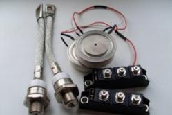
Acquired a sample of LEDs 10 W 900lm warm white light on AliExpress. The price in November 2015 was 23 rubles per share. Order came in a standard bag, checked all serviceable. 
To power LEDs in lighting devices, special blocks are used - electronic drivers, which are converters stabilizing the current, and not the voltage at its output. But since the drivers for them (ordered also on AliExpreess) were still on the road decided to feed from the ballast from energy-saving lamps. I had several such faulty lamps. which burned the filament in the bulb. Typically, such lamps have a voltage converter, and it can be used as a pulsed power supply or LED driver.
We disassemble the fluorescent lamp. 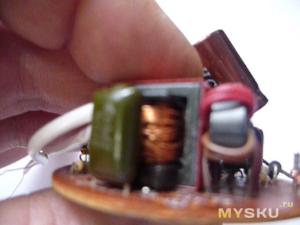
For rework, I took a 20 W lamp, the throttle of which can easily be put into a load of 20 watts. For 10 W of LED no more rework is required. If you plan to power a more powerful LED, you need to take the converter from a more powerful lamp, or install a choke with a large core.
I installed jumpers in the ignition circuit of the lamp. 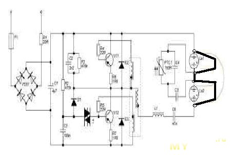
On the choke wound 18 windings of the enamel duct, solder the terminals of the wound winding to the diode bridge, apply a voltage to the lamp and measure the output voltage. In my case, the unit issued 9.7V. Connected the LED through an ammeter, which showed a current passing through the LED at 0.83A. My LED has an operating current of 900mA, but I reduced the current to increase the resource. I assembled the diode bridge on the board in a hinged way.
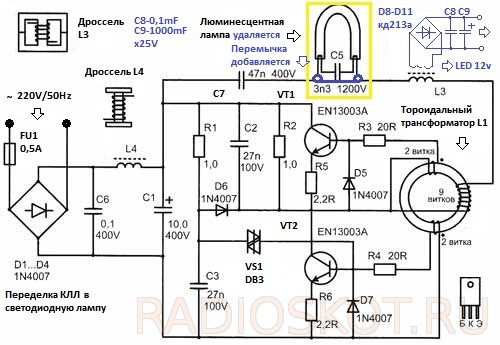
Scheme of alteration. 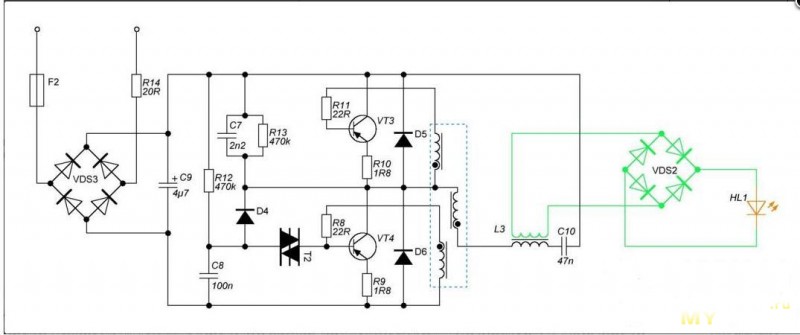
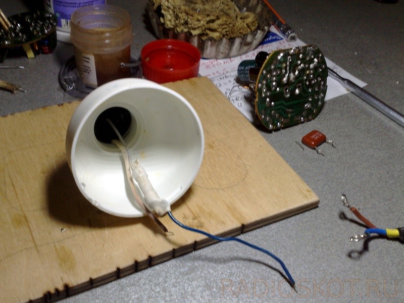
The LED was mounted on the thermopaste on the metal lampshade of the old desk lamp. 
Power board and diode bridge installed in the body of the table lamp. 
When working about an hour the temperature of the LED is 40 degrees. 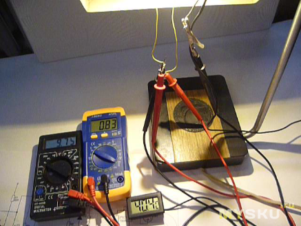
On the eye, the illumination is like a 100-watt incandescent lamp. 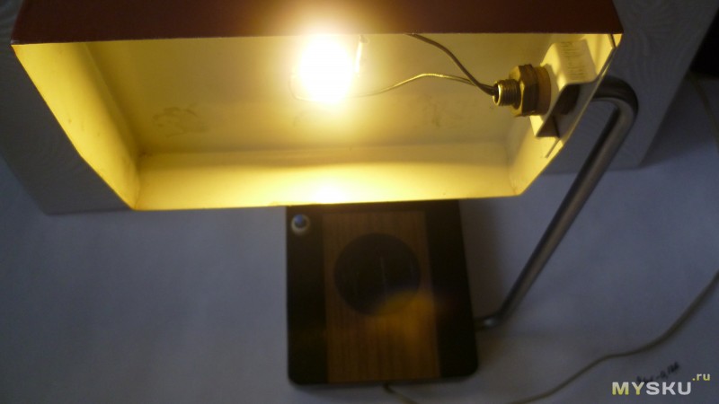
This LED desk lamp has been running for about a month. While everything is fine and then time will tell. As a result, I received a free driver for LEDs. When the factory drivers come, I will compare their work with the homemade.
Who cares about the video?
The boom of fluorescent energy-saving lamps is gradually coming to its end. They have already been replaced by LED lamps, which have undeniable advantages: better economy, instant access to operating conditions, longer service life, they do not contain mercury vapors and do not emit ultraviolet light after burning the phosphor inside the bulb. The only hitch is still the high cost of LED lamps. But if there is a failed fluorescent energy saving lamp, then it can easily be converted into an LED lamp, using the methods listed below.
First a small preface.
Acquired several years ago, energy saving lamps of ECOLIGHT company pretty quickly began to fail. First, the filament burned in the bulb of one lamp, but this malfunction was promptly eliminated by installing a jumper on the printed circuit board in parallel with a tattered filament. The lamp was also perfectly lit from the remaining whole filament. Then the same fate befell the second lamp. After the repair, after having worked for another six months, the remaining filaments were burned first in one lamp, and a month later in another. Contact with fluorescent lamps no longer wanted, and there was an idea about the reworking of failed lamps in LED.
The first lamp had a power of 18 watts and a fairly wide body with a diameter of 55 mm, which led to the idea of installing several dozen ultra-bright white LEDs with a working current of 20 mA, plugging them into the network in series through the diode bridge, and using a condenser as a quenching ballast. The result is the diagram shown in the figure below:
In all, 40 LEDs HL-654H245WC ø4.8 mm with a brightness of 1.5 Cd and an angle of 140 ° were used. The circuit is assembled on two printed circuit boards from one-sided foil-coated fiberglass:

Between each other, the boards are fastened together with one stand in the center. Here's what happened:

Subjectively, the luminescence of this lamp turned out to be about the same as that of a 30-watt incandescent lamp, and the power consumption was only 1.1 W:

The color of the lamp is much colder than the incandescent lamp.
Interestingly, the same and similar brightness LEDs of warm and cold colors available for sale differ in price by 4 times, but even the applied LEDs of warm glow (more expensive) have a bluish tinge in comparison with the incandescent lamp. As for the resulting cost of the manufactured LED lamp, it turned out to be at the level of the finished purchase with the same number of LEDs. It is not known whether there is a rectifier with a smoothing capacitor in these ready-made 220 V lamps. Most likely, no, because it is easier and cheaper to connect in series the pairs of LEDs on and on, and add a ballast capacitor. And let the lamp with a double frequency of the network blink to itself, after all to the Chinese manufacturer there is no point to the view of the consumer.
Considering the rather high cost of forty LEDs (0.125 $ * 40 = 5 $), for reworking a second 9W bulb in a 38.5 mm package

it was decided to use one powerful three-fold LED. The choice fell on EDEX-3LA1-E1 at a cost of $ 1,875, having the following characteristics:
color temperature ............................... 3200 K;
luminous flux (at a current of 700 mA) .............. 130 lm;
angle of illumination 135 °;
operating current ............................................. 700 mA;
voltage .............................................. 4 V.
These LEDs are available for sale ready-made radiators "STAR" at a cost of $ 0.156:
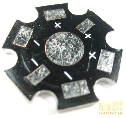
To get a current of up to 700mA for powering such a powerful LED, it was decided to use an existing converter in a burnt out fluorescent lamp. By closing all the leads of the lamp bulb and winding the additional winding on the available choke on the board, such a converter can turn the power source with minimal cost. In fact, the lamp is ready electronic transformer, it is only necessary to provide a stabilized current for powering the LED.
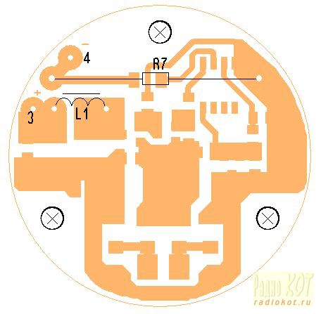
Here is a diagram of an energy-saving lamp, painted directly from the board:

To convert it into an electronic transformer, you just need to remove the flask, close the points 2 and 4 of the board and wind the additional winding on the L2 choke. A rectifier with a filter is connected to the additional winding.
To stabilize the current through the LED, the method proposed in Ref. Its essence consists in winding an additional winding on the control transformer T1 and shunting it with opening field-effect transistors to disrupt oscillations of the converter when the output voltage (current) is exceeded. However, nothing good came out of this. As shown by the analysis of the operation of the above circuit, it takes about 3 ms to restore the converter oscillations to charge the capacitor C3 to the breakdown voltage of the DB3 (30 V) diode. Even with very short-term shunting of the additional winding at T1, the restart time of the converter was about 3 ms. As a result, the regulating characteristic of the converter is incomplete. When trying to "slightly" reduce the output voltage, for example to 90 ... 95%, at the output of the rectifier filter (with an additional power winding of the throttle) instead of a constant voltage, short positive pulses with relatively long dips of 3 ms appeared at once. Those. the control limits were possible only at the initial small section of the converter operation.
Therefore, another circuit solution was used, shown in the figure below:

The additional circuit is an impulse current stabilizer assembled without the use of specialized microcircuits on a widely used low-cost element base. An additional winding is wound on the choke of the lamp, the voltage from which is fed to the diode bridge VD1 ... VD4 with filter capacitors C1, C3. The use of the bridge circuit is caused by the complexity of winding the L2 choke by half a large number of turns with a tap from the middle due to the limited space.
The DA1 chip is equipped with a voltage stabilizer +2.5 V to power the comparator DA2 and a resistive driver of the reference voltage R5, R6. Resistor R7 with a resistance of 0.1 ohms serves as a current sensor. The transistors VT1, VT2 have a power key. In the initial state, when the power is applied, while the current through LED HL1 is not flowing, at the output of comparator DA2 is high, VT1 is closed and VT2 is open through R4. Through the throttle L1, an increasing current flows into the load. If the reference voltage is exceeded on the inverting input of the comparator DA2, the latter switches to a low output state. VT1 opens abruptly and shunts the junction of Z-VT2, closing the latter and causing the self-induction current in the circuits VD5, L1, C4, C5, HL1, R7. After reducing the voltage at the inverting input of the comparator DA2 as the discharge of C4, C5, the latter again goes into a state with a high level at the output. VT1 is closed, VT2 is opened and the whole process is repeated anew. The oscillation frequency with an input voltage of 7 V is 50 ... 70 kHz. The measured efficiency of a pulsed current stabilizer was 86%.
The current value through the LED is selected to be 0.6 A for a more gentle operation and less heating.
The procedure of converting an energy saving lamp
The lamp body is opened with a flat screwdriver (fastening on latches). The upper part with the bulb is carefully disposed of (Caution: In the flask of mercury vapor, if the bulb is damaged, it is necessary to treat the surrounding contacting objects with a solution of potassium permanganate). From the board, the capacitor C5 can be evaporated. in the work he does not participate. Points 2 and 4 on the board are shortened. The L2 choke is soldered and an additional winding of 14 turns is wound around the MGTF-0.1 wire (almost to the full filling of the gap). It is better to use MGTF for a good galvanic isolation.

The throttle is soldered into place. It will not hurt to check the ESR-meter electrolyte C3. If possible, it is better to replace it with a new capacity of 4.7 ... 10 μF x 400 V (105 ° C). This will reduce the ripple frequency of 100 Hz at the output of the converter.
After that, a board made of unilateral foil fiberglass is manufactured:

To produce the L1 throttle, we used the ready-made DP2-0.1 for 100 μH. With it, the knife is taken off the staff winding and wound with a new wire PEV2 ø0.3 mm in uniformly along the entire length of the core in 3 layers. The inductance of the choke is 51 μH. You can also use a commercially available choke with an inductance of 47 μH and rated for at least 1.5 ... 2 A.
The transistor VT2 IRLML6401 can be changed to IRLML6402.
Diodes VD1 ... VD4 SS14 can be replaced with any suitable Schottky SMD-diodes, designed for a current of at least 1A and a reverse voltage of 30 ... 40V, for example SM5818, SM5819.
The diode VD5 SS24 (2A, 40V) will be replaced with SS22, 10BQ015 or similar.
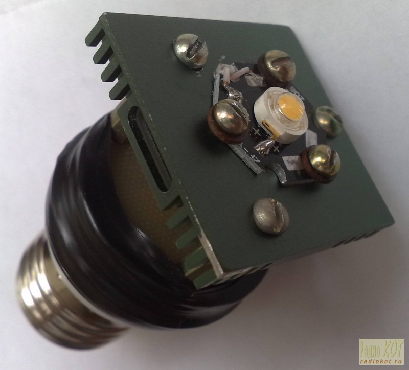
As it was said above, the LED decouples into a ready-made radiator "STAR", which in turn is installed on a more massive radiator. In this case a radiator was used from the old motherboard. With cut off "ears" fastening its dimensions 37.5 x 37.5 x 6 mm. The radiator is attached to an additional board on 3 racks M3x15. The board itself is attached to the top of the lamp body by several turns of electrical tape. Between the staff and additional boards it is necessary to lay an insulation gasket, cut, for example, from non-flinted fiberglass.


The first inclusion of the modified lamp is desirable to produce with a load in the form of a 5-watt resistor with a resistance of 5 ... 6 Ohm with a series-connected ammeter. It is safer to connect the lamp to the 220 V network through a regular incandescent bulb for 40 ... 60 W. In normal operation, its spiral should not glow. At the cathode of VD5 rectangular pulses of frequency 50 ... 70 kHz should be present. The voltage on C3 must be 5 ... 8 V, the current through the load is 0.6 A. More precisely, the current value can be set by selecting the resistance of the resistor R5. After that, you can connect the LED.
Subjectively, the brightness of the glow of the lamp thus modified corresponds to a 30 W incandescent lamp. The hue is warm, but in comparison with the incandescent lamp a little colder. The measured power consumption was 3.3 W:

The cost of the second version of the LED lamp was about 3.2 $.
Literature:
1) How to stabilize an electronic transformer. AE Shufotinsky. Radioamateur №1 / 2010.
ID: 1371
|
How do you like this article? |
While scientists are hiding the speed of light, I've decided to tame the unnecessary fluorescent lamps, converting them into LED. Compact fluorescent lamps (KLL) slightly go back in time, for understandable reasons: less efficiency with respect to LED, environmental insecurity (mercury), ultraviolet radiation dangerous to human eyes, and short-lived.
Like many radio amateurs, a whole box of this "good" has accumulated. Less powerful ones can be used as spare parts, but those that are more powerful, starting from 20W, you can also change power supplies. After all, electronic ballast is a cheap voltage converter, that is, a simple and affordable switching power supply that can power devices up to 30-40W (depends on the CFL), and even more if you change the output choke and transistors. Those radio amateurs who live in remote places, or in certain situations, these "energy-saving" will be useful. So, do not rush to throw them out after a failure - and they do not work for long!
In my case, about a year ago (in the spring of 2014), starting to experiment with electronic ballast, in search of a body for alteration in lED lamp, returning home in the evening from work, it dawned on me - seeing on the sidewalk a can of coke. After all, an aluminum casing made from a 0.25L beverage is just suitable as a heat sink for dissipating heat from an LED strip. And also, ideally sits under the body of CFL "Vitoone" with the E27 cap, at 25 W. And in aesthetics, not bad!

Having manufactured several redesigned LED-lamps, I began to test them in different operating conditions. One of them works in the utility room in the heat and frost (with ventilation holes), the other in the living room (without an opening in the plastic socket). Another one is connected to a three-meter lED strip. Almost a year has passed, and they still serve without fail! Well, and given that on the topic of LEDs, the article appears more and more, I had to finally write about my time-tested ideas.
LAMP LED UNIVERSAL
Energy-saving lamps are widely used in everyday life and production, they eventually become unusable, and meanwhile many of them can be restored after a simple repair. If the luminaire itself is out of order, then from the electronic "stuffing" it is possible to make a fairly powerful power supply for any desired voltage.
What does the power supply of the energy-saving lamp look like?
In everyday life, a compact, but powerful low-voltage power supply is often required, you can do this using an energy-saving lamp that is out of order. Lamps most often fail lamps, and the power supply remains in working order.
In order to make a power supply, it is necessary to understand the principle of the work of electronics contained in an energy-saving lamp.
Advantages of switching power supplies
In recent years, there has been a clear tendency to withdraw from the classical transformer power supplies to the impulse ones. This is due, first of all, to the large disadvantages of transformer power supplies, such as large mass, low overload capacity, low efficiency.
Elimination of these shortcomings in impulse power supply units, as well as the development of the element base, made it possible to widely use these power points for devices with a power from a few watts to many kilowatts.
Power supply circuit diagram
The principle of operation of a switching power supply in an energy-saving lamp is exactly the same as in any other device, for example, a computer or a television set.
In general, the operation of a switching power supply can be described as follows:
- The alternating current is converted into a constant without changing its voltage, i.e. 220 V.
- A pulse-width transistor transducer converts constant pressure in rectangular pulses, with a frequency of 20 to 40 kHz (depending on the model of the lamp).
- This voltage is fed through the throttle to the luminaire.
Let's consider the scheme and the order of operation of the pulsed lamp power supply (see below) in more detail.

Electronic ballast of energy-saving lamps
The mains voltage is supplied to the bridge rectifier (VD1-VD4) through the limiting resistor R 0 of the small resistance, then the rectified voltage is smoothed out on the filtering high-voltage capacitor (C 0) and fed to the transistor converter via the smoothing filter (L0).
The start of the transistor converter occurs at the moment when the voltage across the capacitor C1 exceeds the threshold of opening of the VD2 diode. This will start the generator on transistors VT1 and VT2, so that there is an autogeneration at a frequency of about 20 kHz.
Other circuit elements, such as R2, C8 and C11, play an auxiliary role, making it easier to start the generator. Resistors R7 and R8 increase the closing speed of transistors.
And the resistors R5 and R6 serve as restrictive in the circuits of the bases of transistors, R3 and R4 protect them from saturation, and in case of breakdown play the role of fuses.
Diodes VD7, VD6 - protective, although in many transistors designed to work in similar devices, such diodes are built-in.
TV1 - transformer, with its windings TV1-1 and TV1-2, the feedback voltage from the generator output is fed to the basic circuits of the transistors, thereby creating conditions for the generator to work.
In the figure above, the details to be removed when redoing the block are highlighted in red, the points A-A 'need to be bridged.
Redesign of the block
Before you begin to rework the power supply, you need to determine how much power you need to have at the output, which will determine the depth of the upgrade. So, if you need a power of 20-30 W, the conversion will be minimal and will not require much intervention in the existing scheme. If you need to get a power of 50 or more watts, then modernization will require more thorough.
It should be borne in mind that the output of the power supply will be a constant voltage, not an alternating voltage. It is impossible to obtain an alternating voltage of 50 Hz from such a power unit.
Determine the power
Power can be calculated by the formula:
P - power, W;
I is the current strength, A;
U is the voltage, V.
For example, take a power supply with the following parameters: voltage - 12 V, current - 2 A, then the power will be:
Taking into account the overload, it is possible to take 24-26 W, so that such a unit requires minimal interference with the 25 W energy saving lamp circuit.
New Details
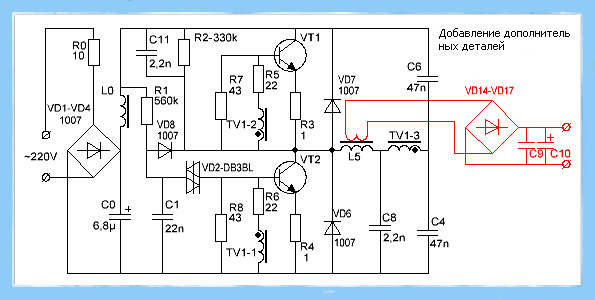
Adding new parts to the schematic
The added parts are highlighted in red, these are:
- diode bridge VD14-VD17;
- two capacitors C 9, C 10;
- the additional winding placed on the ballast throttle L5, the number of turns is selected experimentally.
The added winding on the throttle plays another important role of the separation transformer, preventing the mains voltage from reaching the output of the power supply unit.
To determine the required number of turns in the winding to be added, the following steps should be performed:
- on the choke wound a winding, about 10 turns of any wire;
- connect with the load resistance, the power is not less than 30 W and the resistance is about 5-6 Ohm;
- include in the network, measure the voltage on the load resistance;
- the obtained value is divided by the number of turns, it is learned how many volts there are per turn;
- calculate the required number of turns for a constant winding.
A more detailed calculation is given below.

Test inclusion of the converted power unit
After this, it is easy to calculate the required number of turns. For this, the voltage that is planned to be received from this unit is divided by the voltage of one turn, the number of turns is obtained, about 5-10% is added to the result obtained.
W = U out / U whit, where
W is the number of turns;
Uout - the required output voltage of the power supply;
U vit - voltage for one turn.

Winding of an additional winding on a regular throttle
The original winding of the throttle is energized! When winding over it additional winding, it is necessary to provide for winding insulation, especially if the wire is wound PEL, in enamel insulation. For interwinding insulation, a polytetrafluoroethylene tape can be used to seal the threaded joints used by plumbers, its thickness being only 0.2 mm.
The power in such a unit is limited by the overall power of the transformer used and permissible current transistors.
Power supply of high power
This will require a more sophisticated upgrade:
- an additional transformer on the ferrite ring;
- replacement of transistors;
- installation of transistors on radiators;
- increase capacitance of some capacitors.
As a result of this upgrade, a power supply unit with a power of up to 100 W is obtained, with an output voltage of 12 V. It is capable of providing a current of 8-9 amperes. This is enough to power, for example, a medium power screwdriver.
The scheme of the upgraded power supply is shown in the figure below.

100 W power supply unit
As seen in the diagram, the resistor R 0 is replaced by a more powerful (3-watt) resistor, its resistance is reduced to 5 ohms. It can be replaced by two 2-watt 10 ohms, connecting them in parallel. Further, C 0 - its capacity is increased to 100 mkf, with a working voltage of 350 V. If it is undesirable to increase the dimensions of the power supply, then it is possible to find a miniature capacitor of such capacity, in particular, it can be taken from a camera-soap box.
To ensure reliable operation of the unit, it is useful to slightly decrease the values of the resistors R 5 and R 6, to 18-15 Ohm, and also to increase the power of the resistors R 7, R 8 and R 3, R 4. If the generation frequency is not high, then the capacitors C 3 and C 4 - 68n should be increased.
The manufacture of a transformer can be the most difficult. For this purpose, ferrite rings of the appropriate size and magnetic permeability are most often used in pulse blocks.
The calculation of such transformers is rather complicated, but there are many programs on the Internet, with which it is very easy to do, for example, "Lite-CalcIT pulse transformer calculation program".

What does a pulse transformer look like?
The calculation carried out with the help of this program gave the following results:
For the core, a ferrite ring is used, its outer diameter is 40, the inner diameter is 22, and the thickness is 20 mm. Primary winding with PEL wire - 0.85 mm 2 has 63 turns, and two secondary wires with the same wire - 12.
The secondary winding must be wound up in two wires at the same time, and it is desirable to slightly twist them first along the entire length, since these transformers are very sensitive to the asymmetry of the windings. If this condition is not met, the diodes VD14 and VD15 will heat up unevenly, and this will further increase the asymmetry, which will eventually disable them.
But such transformers easily forgive significant errors when calculating the number of turns, up to 30%.
Since this circuit was originally designed to work with a lamp with a power of 20 W, transistors 13003 are installed. In the figure below, the position (1) is medium power transistors, they should be replaced by more powerful ones, for example, 13007, as in position (2). Perhaps they will have to be installed on a metal plate (radiator), an area of about 30 cm 2.

Test
Trial inclusion should be done in compliance with some precautions, so as not to disable the power supply:
- The first test inclusion is done through a 100 W incandescent lamp to limit the current to the power supply.
- The output must be connected to a 3-4 Ohm load resistor, 50-60 W capacity.
- If everything went well, give 5-10 minutes to work, switch off and check the degree of heating of the transformer, transistors and rectifier diodes.
If errors were not made during the replacement of parts, the power supply should be made without problems.
If the test inclusion showed the operability of the unit, it remains to test it in full load mode. To do this, the resistor of the load resistor should be reduced to 1.2-2 ohms and plugged in directly without a light bulb for 1-2 minutes. Then turn off and check the temperature of the transistors: if it exceeds 60 0 C, they will have to be installed on the radiators.
As a radiator can be used as a factory radiator, which will be the most correct solution, and an aluminum plate, a thickness of at least 4 mm and an area of 30 square cm. Under the transistors it is necessary to lay a mica gasket, fasten them to the radiator with screws with insulating sleeves and washers.
A block of a lamp. Video
On how to make a switching power supply from an economy lamp, the video is below.
A pulsed power supply from a ballast of energy-saving lamps can be made with your own hands, having minimum skills of working with a soldering iron.
Over time, in the glove box of any radio amateur, a huge amount of electronic stuffing from energy saving light bulbs, and many radio components of them can be actively used in other radio amateur tracks. So the high-voltage generator from the ballast of the usual energy-saving lamp is assembled for 5 minutes, and the power supply of the Tesla generator is already there.

As practice shows, daylight lamps work for years. But over time, their luminosity diminishes. Such lamps, of course, can still serve you until the flask filled with an inert gas breaks through a high-voltage discharge, but it is not advisable to bring them to this state, because the electronic part can also burn, but you can still use it.

Inside the energy-saving housing there is electronic circuit - ballast. This is a ready-to-raise high-voltage converter of the AC-DC type, it is necessary to increase the standard 220 volts to 1000 volts. Attention, at its output there is a life-threatening strain, so during the experiments observe extreme caution and always remember about.
To build a high-voltage generator circuit, we will need a line transformer, it can be borrowed from a horizontal scan unit, such people are massively discarded, so it is not at all a problem to find it. Another important component of the high-voltage design is a capacitor. By the way, it can also be found in a horizontal scan unit, for example 2200 pF 5 kV. The voltage from the ballast goes to the winding of the line transformer not directly, but through the capacitor, this connection protects the ballast circuit. On the correct extraction of the line transformer, I propose to learn from the video:
Using a multimeter on the transformer, we find the winding with the maximum resistance (except for the high-voltage) and apply voltage to it from the ballast. Such a high-voltage generator can be used in experiments with electricity. If you add two metal bars - we get the "ladder of Jacob". Even on it you can collect, because the circuit is able to feed a line transformer in a day, and the voltage at the output of a line transformer of 5 kV.