Antipyretics for children are prescribed by a pediatrician. But there are situations of emergency care for fever, when the child needs to give the medicine immediately. Then the parents take responsibility and apply antipyretic drugs. What is allowed to give to infants? How can you bring down the temperature in older children? Which medications are the safest?
Hello, dear readers and guests of the site "Notes electrician."
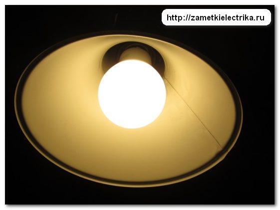
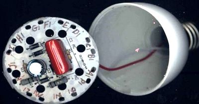
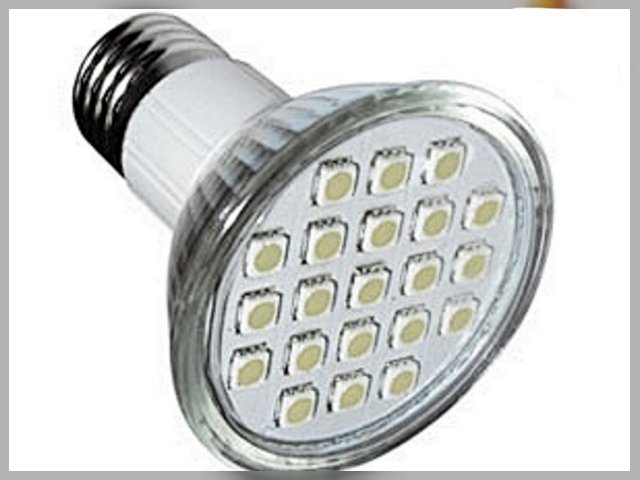
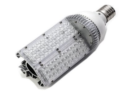
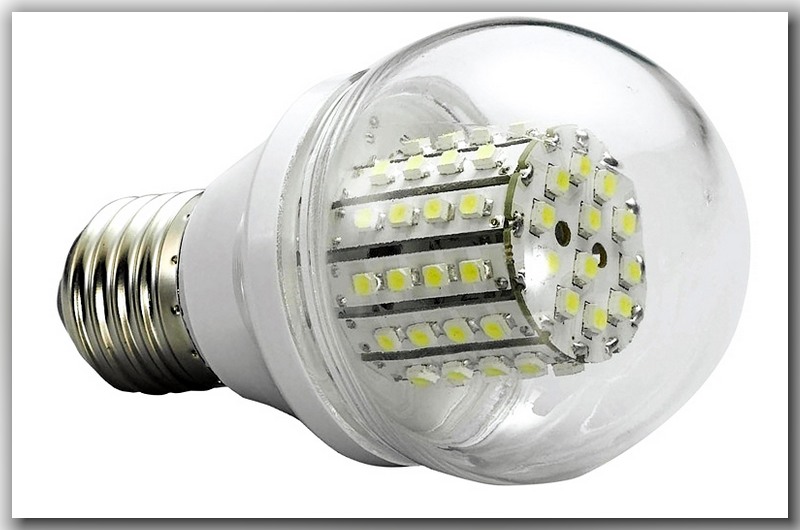
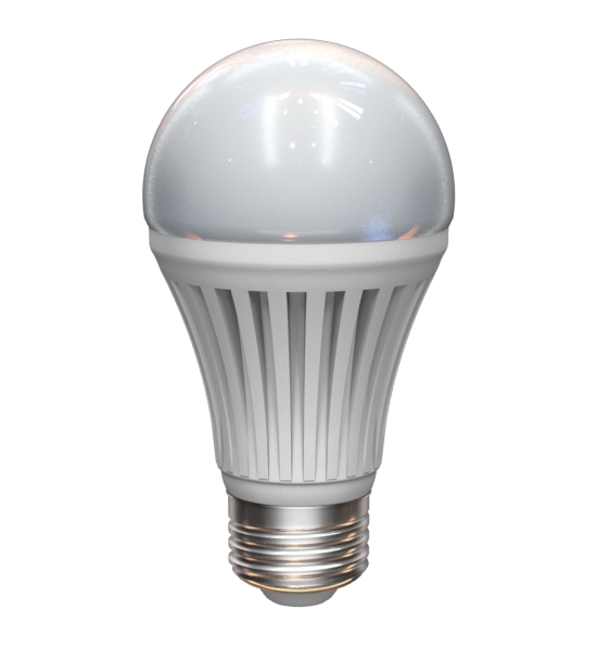
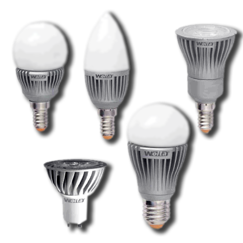
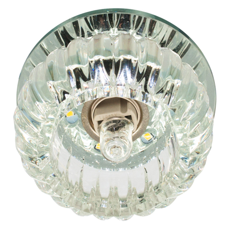
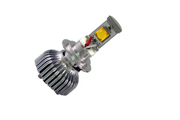
Today I decided to tell you about the device lED Bulb EKF series of FLL-A power 9 (W).
I compared this lamp in my experiments (,) with an incandescent lamp and a compact fluorescent lamp (CFL), and it had clear advantages in many respects.
Now let's analyze it and see what is inside. I think that you will be no less interesting than me.
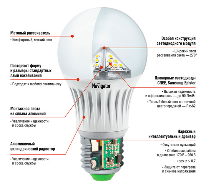
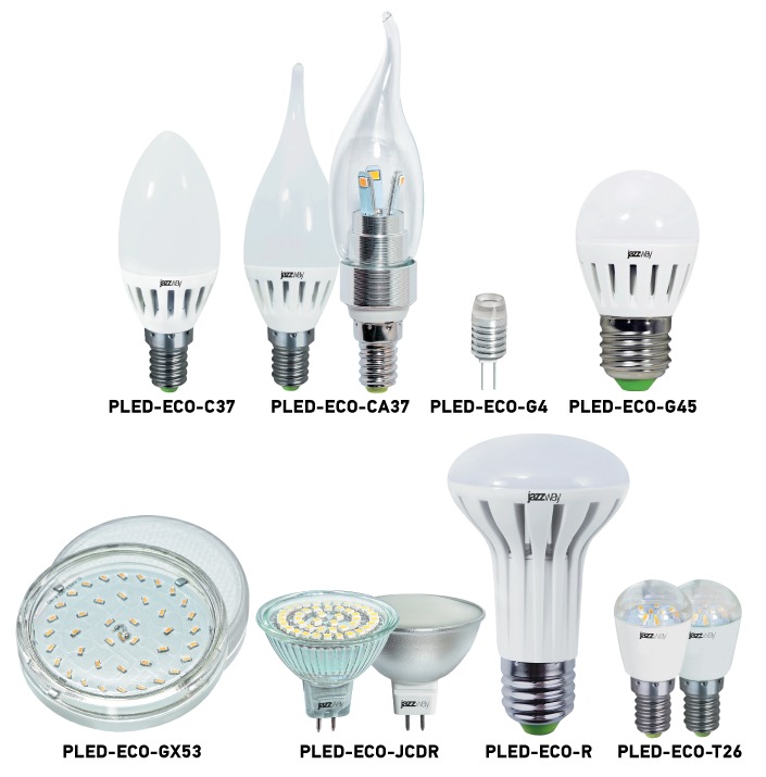
So, the device of modern LED lamps consists of the following components:
- diffuser
- board with LEDs (cluster)
- radiator (depending on model and lamp power)
- power supply of LEDs (driver)
- socle
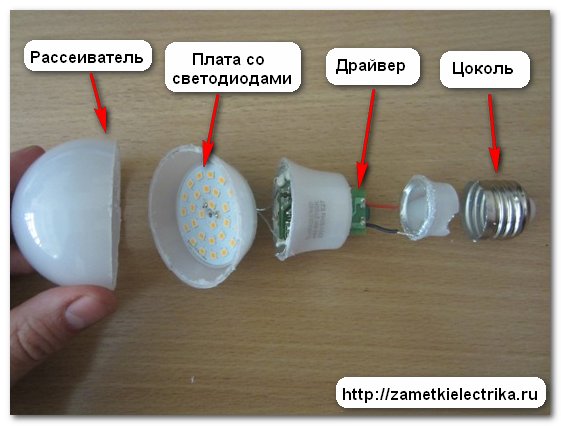
And now consider each component separately as the EKF lamp is parsed.
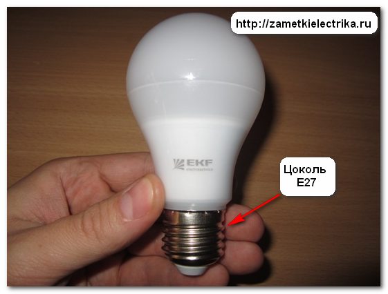
The lamp in question has a standard E27 base. It is fixed to the lamp body with the aid of point depressions (coring) along the circumference. To remove the base, it is necessary to drill out the coring sites or to make a cut with a hacksaw.
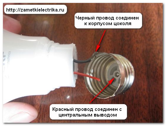
The red wire connects to the central contact of the cap, and the black wire is soldered to the thread.
The supply wires (black and red) are very short, and if you disassemble the LED lamp for repair, you need to take into account and stock up the wires for their further build-up.
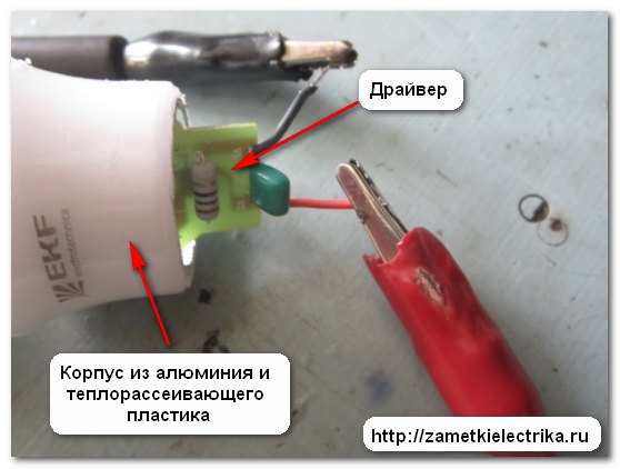
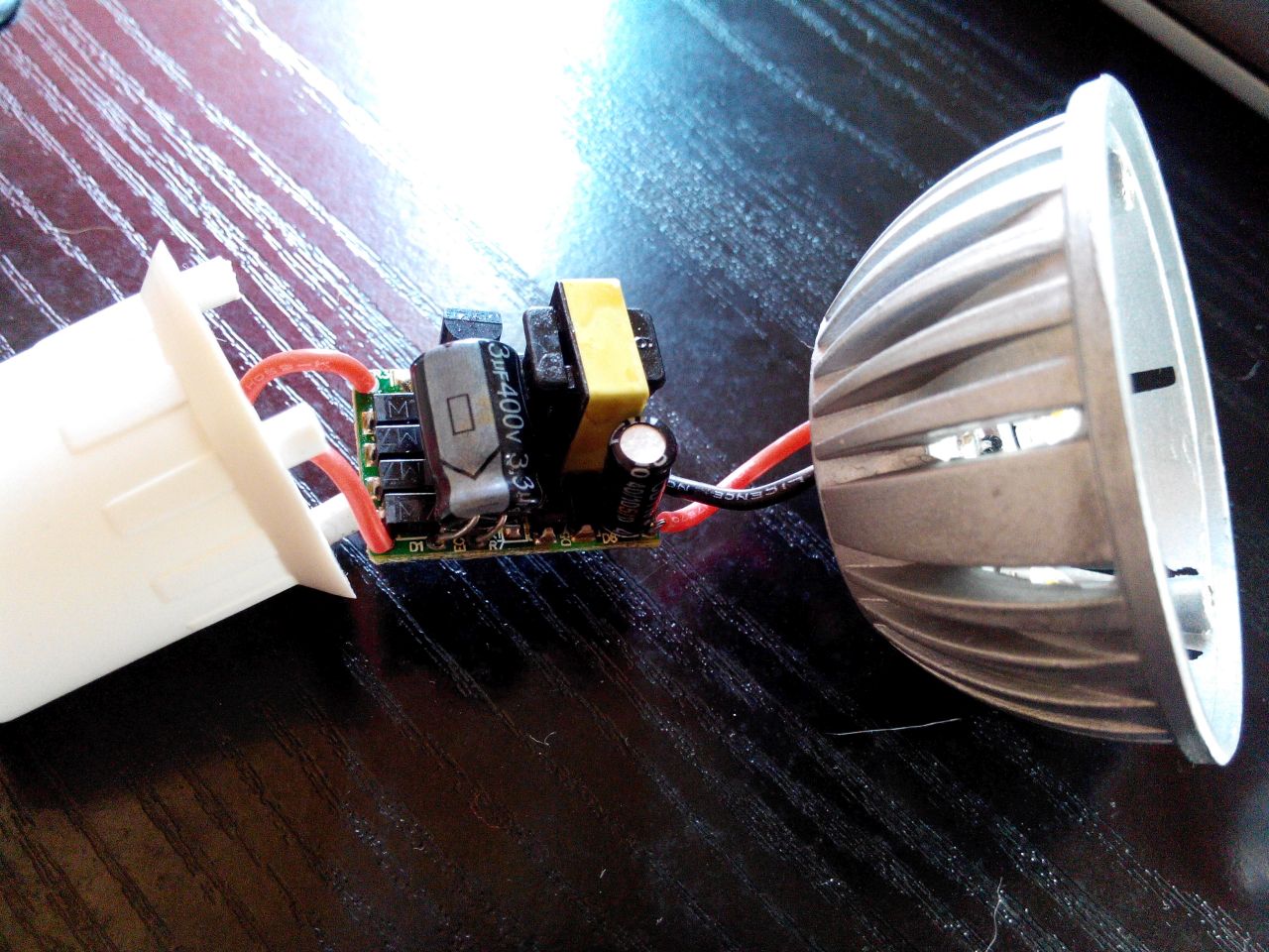
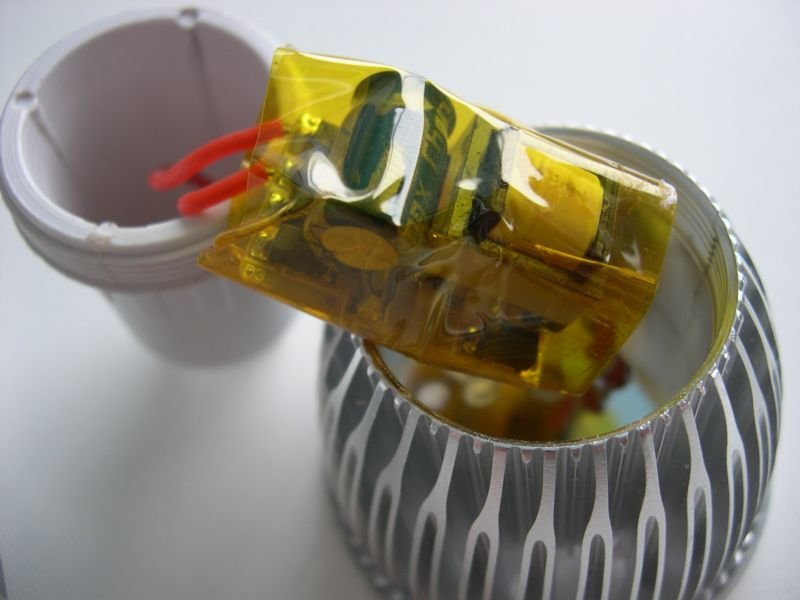
Through the opened hole, the driver is visible, which is fixed with the help of silicone to the lamp body. But you can extract it only from the side of the scatterer.
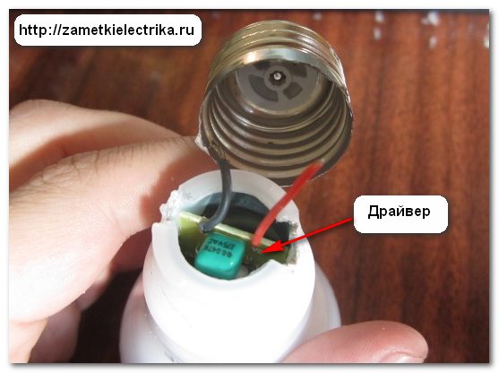
The driver is the power source of the LED board (cluster). It converts the alternating voltage of the network 220 (V) into a constant current source. The drivers are characterized by power and output current parameters.
There are several types of power supply circuits for LEDs.
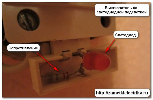
The simplest circuits are performed on a resistor that limits the current of the LED. In this case, you just need to choose the correct resistor. Such power schemes are most often found in switches with LED backlighting. This photo I took from an article in which I talked about.
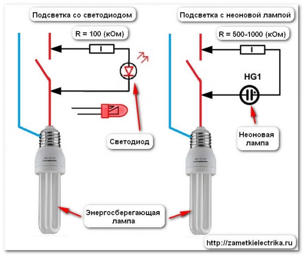
The circuits are slightly more complicated on the diode bridge (bridge rectification circuit), from the output of which the rectified voltage is applied to the series-connected LEDs. At the output of the diode bridge, an electrolytic capacitor is also installed to smooth out the ripple of the rectified voltage.
In the above schemes there is no galvanic isolation with the primary voltage of the network, they have low efficiency and a large coefficient of ripple. Their main advantage lies in the simplicity of repair, low cost and small dimensions.
In modern LED lamps, the most commonly used drivers are those based on a pulse converter. Their main advantages are high efficiency and a minimum of pulsations. But they are at a price several times more expensive than the previous ones.
By the way, in the near future I plan to measure the pulsation coefficients of LED and fluorescent lamps from different manufacturers. To not miss the release of new articles - subscribe to the newsletter.
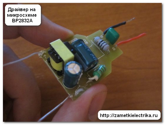
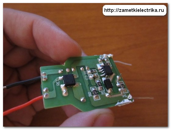
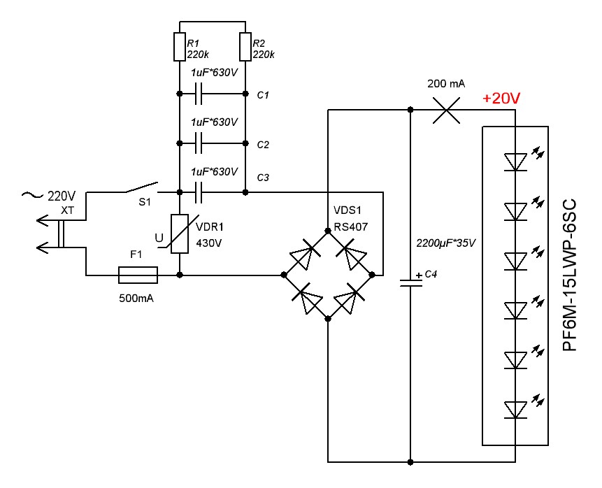
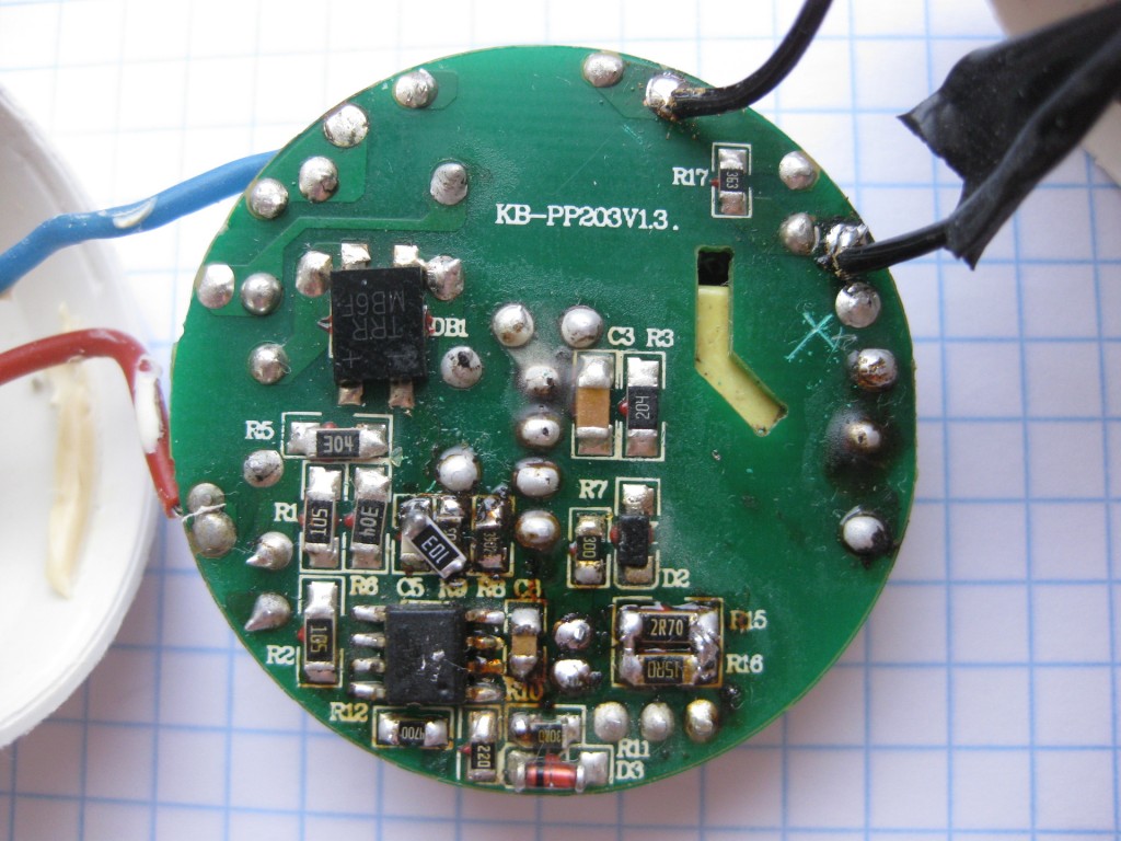
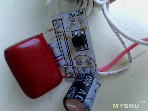
In the EKF LED lamp in question, a driver is installed on the BP2832A chip.
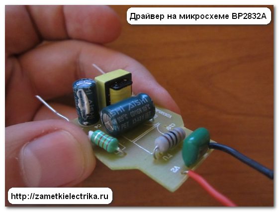
The driver is attached to the body with a silicone paste.
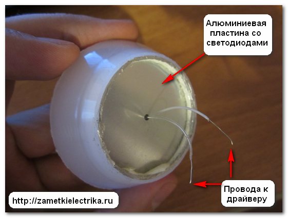
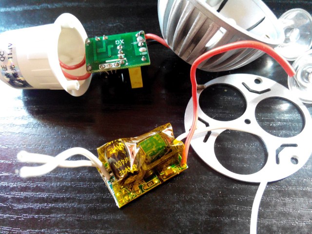
To get to the driver, I had to saw off the diffuser and take out the board with the LEDs.
The red and black wires are the 220 (V) power supply from the lamp base, and the colorless ones are the power to the LED board.
Here is a typical driver scheme on the BP2832A chip, taken from the passport. There you can get acquainted with its parameters and technical characteristics.

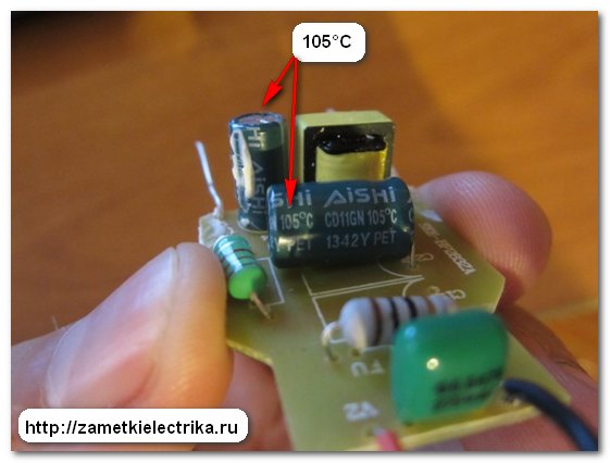
The operating mode of the driver is in the range from 85 (V) to 265 (V) mains voltage, there is protection against short circuit, electrolytic capacitors are used, designed for continuous operation at high temperatures (up to 105 ° C).
The housing of the EKF LED lamp is made of aluminum and heat dissipating plastic, which provides good heat dissipation, which means that the LED and driver life is extended (up to 40,000 hours are stated for the passport).
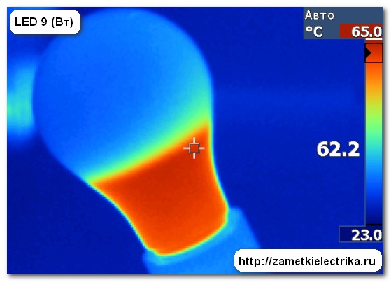
The maximum heating temperature of this LED lamp is 65 ° C. Read about this in experiments (I indicated the links at the very beginning of the article).
The more powerful LED lamps, for better heat dissipation, have a radiator that is attached to the aluminum LED board through the thermal paste layer.
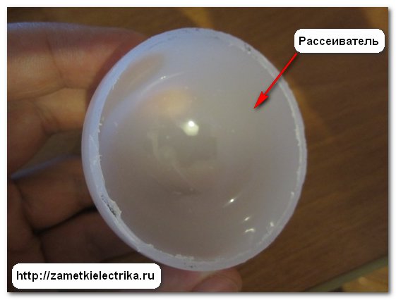
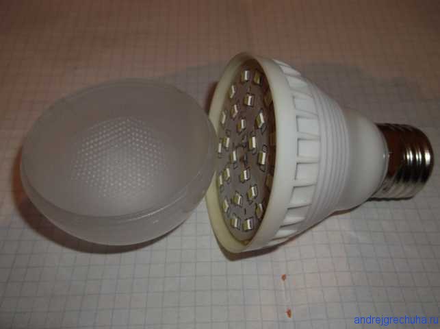
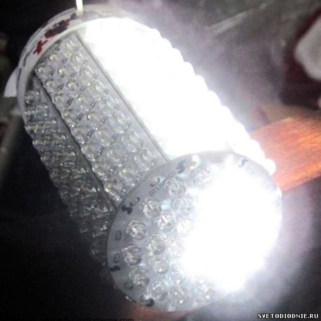
The diffuser is made of plastic (polycarbonate) and by means of it, a uniform dispersion of the light flux is achieved.
But the glow without a diffuser.
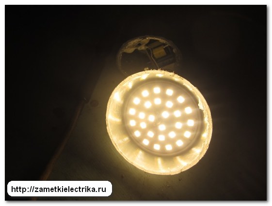
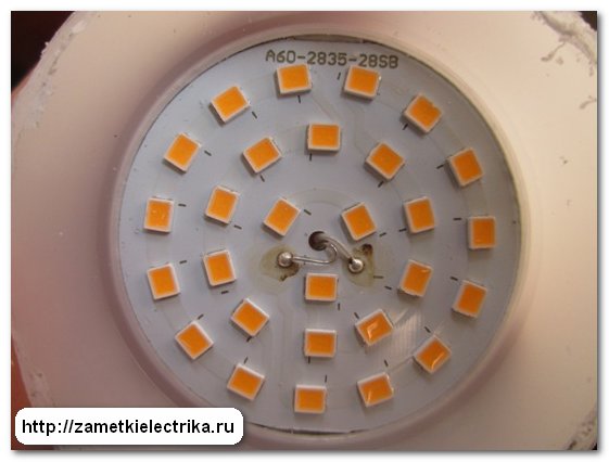
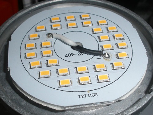
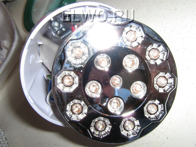
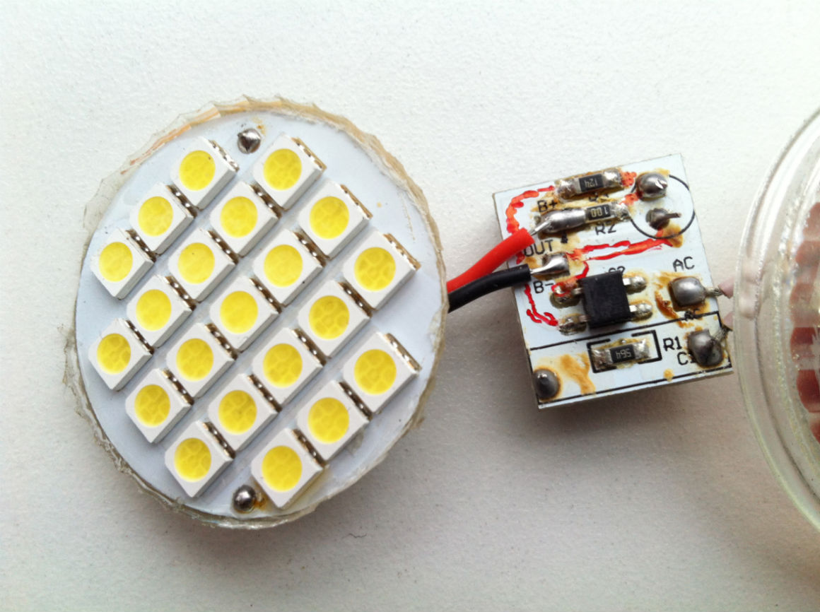
Well, we got to the LED board or in other words, the cluster.
On the round aluminum plate (for better heat dissipation) 28 SMD LEDs are placed through the insulation layer.
LEDs are connected in two parallel branches of 14 LEDs in each branch. The LEDs in each branch are connected in series. If even one light-emitting diode burns, the entire branch will not burn, but the second branch will remain in operation.
But the video, shot on the basis of this article:
P.S. At the end of the article I want to note that the design of the LED-lamp EKF from the point of view of repair is not very successful, the lamp can not be disassembled without sawing the diffuser and drilling the cap.
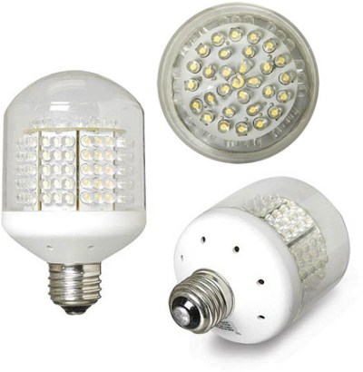
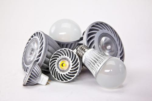
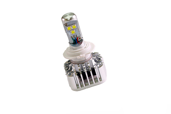
In the photo you can see a lot of LED lamps. They got me a gift. There was an opportunity to study the arrangement of these lamps, electrical circuits, and also to repair these lamps. The most important thing is to find out the causes of failure, since the service life indicated on the box does not always coincide with the service life.
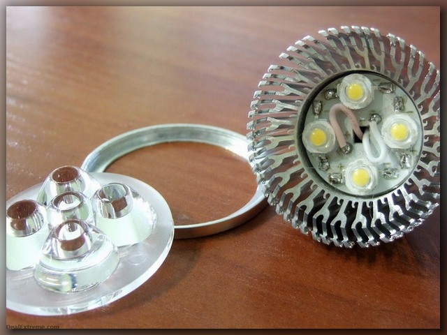
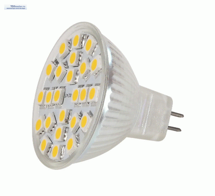
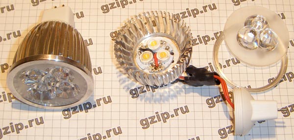
Lamps like MR-16 are dismantled without any effort.
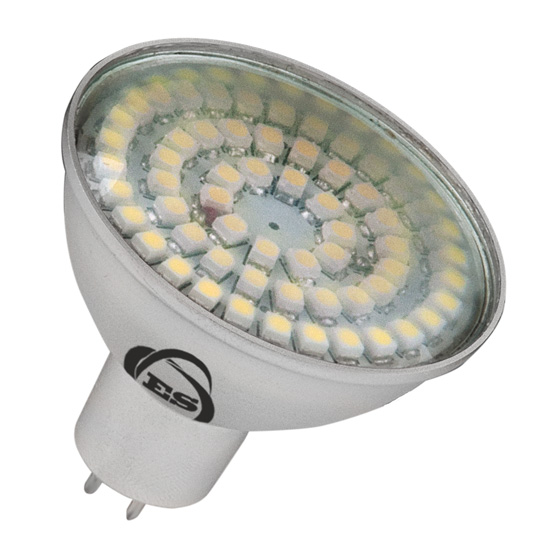
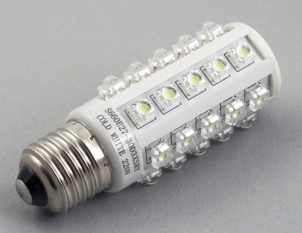
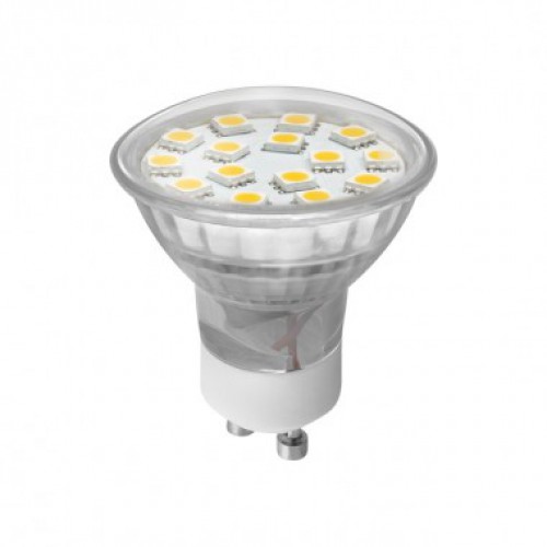
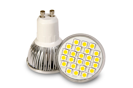
Judging by the label, the lamp is model MR-16-2835-F27. In its case there are 27 SMD LEDs. They emit 350 lumens. This lamp is suitable for connection to a network alternating current 220-240 V. The power consumption is 3.5 watts. Such a lamp glows white, the temperature of which is 4100 degrees Kelvin and creates a narrow flow due to a flow angle equal to 120 degrees. The type of socket used is "GU5.3", having 2 pins, the distance between them is 5.3 mm. The case is made of aluminum, the lamp has a removable base, which is fixed with two screws. Glass protecting the lamp from damage is planted on the glue at three points.
How to disassemble the MR-16 LED bulb
To identify the cause of the failure, you need to disassemble the lamp body. This is done without much effort.
As you can see in the photo, a ribbed surface is visible on the body. It is designed for better heat dissipation. We put a screwdriver in one of the ribs and try to raise the glass.
Happened. You can see the printed circuit board, it is glued to the body. Having pierced it with a screwdriver, it separates.
Repair of LED bulbs MR-16
Among the first, a lamp was disassembled, inside of which the LED burned out. The printed circuit board, which is made of fiberglass, was burned through.
This lamp is suitable as a "donor", from it the necessary spare parts for repair of other lamps will be taken. The other 9 lamps also burned LEDs. Since the driver is intact, the cause of the failure is the LEDs.
The circuit of the LED lamp MR-16
To reduce the repair time of lamps, it is necessary to create it electrical circuit. It's pretty simple.
Attention! The circuit is connected to the network phase by a galvanic method. Do not use it to power any devices.
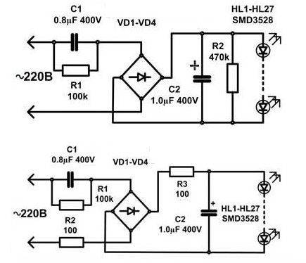
How does the circuit work? The diode bridge VD1-VD4 is supplied with a voltage of 220 V through the capacitor C1. It then goes to the LEDs HL1-HL27, which are connected in series in series. The number of LEDs can be of the order of 80 pieces. The capacitor C2 (the larger the capacitance, the better) is the smoothing pulsation of the rectified voltage. It excludes the flickering of light having a frequency of 100 Hz. For the discharge of C1, R1 was installed. This is necessary in order to eliminate the electric shock when replacing the lamp. C2 is protected from R2 breakdown in the event that an open circuit appears. R1, R2 as such do not accept work in the scheme.
C1- red, C2- black, diode bridge- housing with four legs.
Classical driver circuit for LED lamps up to 5 W
The electroscheme of lamps has no protection elements. It will take a resistor of 100-200 ohms, or two. One will be installed in the connection circuit, the second will serve as protection against current drops.
Above is a diagram with protective resistors. R3 protects the LEDs and C2 capacitor, R2 in turn - the diode bridge. This driver is perfect for lamps that are less than 5W in power. It will easily power a lamp that has 80 LEDs such as SMD3528. If you want to reduce or increase the current, perform manipulations with the capacitor C1. To avoid flicker, increase the capacitance C2.
The efficiency of such a driver is less than 50%. For example, for a lamp MR-16-2835-F27 you need a resistor of 6.1 kΩ and a power of 4 watts. Then the driver will consume power that exceeds the power consumption of the LEDs. Because of the large allocation of thermal energy to place it in a small lamp body will not work. In this case, you can separately make the case for this driver.
It should be remembered that the efficiency of the lamp depends directly on the number of LEDs.
Search for faulty LEDs
After the protective glass has been removed, you can inspect the LEDs. If the slightest black spot on the surface of the LED is detected, it has failed. Inspect soldering points, inspect the quality of the terminals. In one of the lamps, four badly soldered LEDs were detected
LEDs with black dots were marked with a cross. With external inspection, the LEDs can be entire. Therefore, you need to ring them with a tester. To test you need a little more than 3 V. Battery, battery, power supply. A current-limiting resistor having a nominal value of 1 kΩ is subsequently connected to the power supply.
Touch probes touch the LED. In one direction, the resistance should be small (the LED can glow), in the other - be equal to tens of mega-ohms.
During the test, it is necessary to fix the lamp. A bank can come to the rescue.
You can test the LED without special devices if the device driver is intact. The lamp's base is supplied with voltage, the leads of the LEDs are short-circuited by tweezers or a piece of wire.
If you see the glow of all the LEDs, the shorted is defective. But this method is suitable, if the circuit has failed 1 LED.
If a circuit breaks several LEDs, the lamp will light. Only its luminous flux decreases. Just short the places of the sites to which the LEDs were soldered.
Other LED Faults
If during the verification it turned out that the LEDs are working, then it's the driver or the place of soldering.
In this lamp, a cold soldering of the conductor was detected. Soot, which appeared due to poor soldering, settled on the lanes of the board. To remove soot, we needed a cloth moistened with alcohol. The wire fell out, zaludili and soldered. This lamp has earned.
Of all the lamps, one had a driver failure. The diode bridge was replaced by 4 diodes "IN4007", which are rated for 1 A and for a reverse voltage of 1000 V.
Soldering SMD LEDs
To replace the faulty LED, it is necessary to remove it, without damaging the printed conductors. The usual soldering iron can be done with difficulty, it is better to put on a soldering iron sting, made of copper wire.
When sealing the LED, it is necessary to monitor the polarity. Install the LED in place of the soldering, take a soldering iron for 10-15 W and heat its ends.
If the LED is burnt, and the board is charring, this place should be cleaned. Since it is a conductor. If the platform is exfoliated, the LED mono is soldered to the "neighbors". This is done if the tracks lead to them. Just take a piece of wire, fold two or three times and solder.
Analysis of the causes of failure of LED lamps MR-16-2835-F27
According to the table, it can be concluded that the breakdown of lamps is often due to the failure of the LEDs. The reason for this is the lack of protection in the circuit. Although there is a place for the varistor on the board.
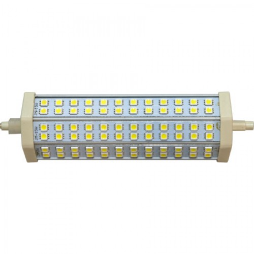
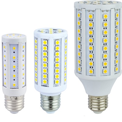
Repair of LED lamp series "LL-CORN" (corn lamp) E27 4.6 W 36x5050SMD
The technology of repair of the "corn" lamp differs from the repair above the lamp shown.
Repair of such a lamp is simple, since the LEDs are located on the body. And for the vertebra, no extra actions are required. This lamp was disassembled solely because of interest.
The technique of testing "corn" does not differ from the above. Only in the case of these lamps there are 3 LEDs. When the dial is all 3 should light up.
If one of the LEDs is damaged, short-circuit it or solder a new one. At the service life of the lamp, this is not reflected. The lamp driver does not have a decoupling transformer. Therefore, any touch of the LED track is unacceptable.
If the LEDs are intact, the driver case. In order to inspect it, it is necessary to disassemble the case.
To get to the driver, you need to remove the bezel. Prydte it with a screwdriver in the weakest place, it must come unstuck.
The driver has the same circuit as our first lamp, with the difference that C1-1μF, C2-4.7 μF. The wires are long, so the driver stretches effortlessly. After work on replacing the LED, the bezel was seated on the glue "Moment".
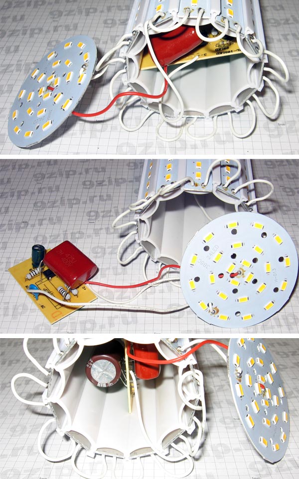
Repair of LED lamp "LL-CORN" (corn lamp) E27 12 W 80x5050SMD
Repair of a 12-watt lamp is done according to the same scheme. There were no burned LEDs on the case, so I had to open the case to inspect the driver.
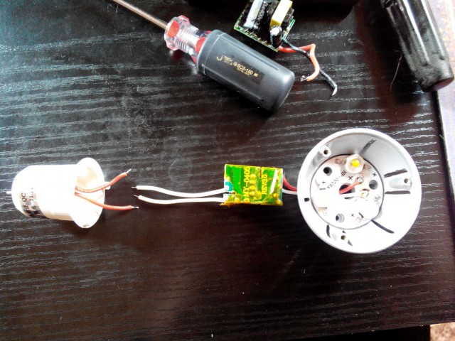
This lamp has problems. The driver wires were too short, I had to remove the cap.
The plinth is made of aluminum. He was attached to the body with a pincer. Therefore, it was necessary to drill the attachment points with a drill, the diameter of which is 1.5 mm. Then the base was pinched with a knife and removed. Wires inside were forced to eat.
Inside there were 2 identical drivers, each of which fed 43 diode.
The driver is wrapped in a heat-shrink tubing, it had to be cut.
After troubleshooting, the driver is placed the same tube and is clamped with a plastic screed.
The driver circuit implies protection. C1 protects against impulse surges, R2, R3 from surges. During the verification work, the breaks of R2 were observed. Most likely, the lamp was supplied with a voltage exceeding the norm. There was no 10 ohm resistor, so a 5.1 ohm resistor was soldered. The lamp lit up. Next, you had to connect the driver to the cap.
The first thing short wires were replaced by longer ones. Drivers were connected by supply voltage. To attach the wires to the threaded part of the plinth, it is necessary to clamp them between the plastic casing and the plinth.
And how to connect to the central contact? Aluminum is not soldered, so the wire was soldered to a brass plate, in which a hole for M 2.5 was drilled. A similar hole was drilled in contact. All this was twisted by a screw. Next, he was wearing a socle and pinned to the lamp body. The lamp was fit to work.
Repair of LED lamps of the "LLB" series E27 6 W 128-1
The design of the lamp is ideal for repair. The case is easily dismantled.
It is necessary to hold the base with one hand, and turn the protective cover anti-clockwise in the second.
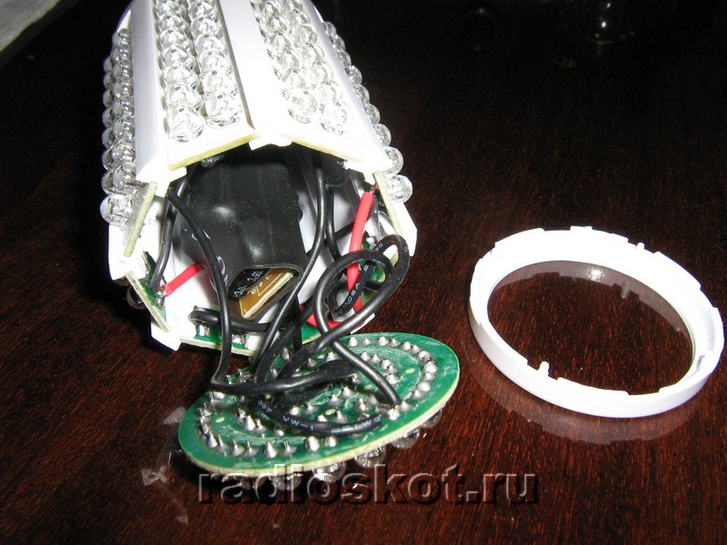
Under the body there are five rectangular boards on which the LEDs are soldered. The rectangle is soldered to the round board on which the driver circuit is located.
To gain access to the LED pins, you need to remove one of the covers. For ease of operation, it is better to remove the board located at the voltage points of the driver. In the photo it can be seen that this wall is parallel to the capacitor body and is remote from it to the maximum distance.
To remove the card, it is necessary to warm the soldering places with a soldering iron. Then, to remove it, heat the solder on a round board and it disconnects.
Access for inspection of breakages is open. The driver is made in a simple scheme. Checking it rectifier diodes, as well as all the LEDs (in this lamp there are 128 of them) did not show a problem.
When I examined the places of soldering, I found that they were missing at some points. These places were soldered, except for this I connected printed circuit boards at the corners.
When you look at the light, these tracks are clearly visible and you can easily determine where the track is.
Before collecting the lamp, it was necessary to verify it. For this purpose, a jumper was installed on the motherboard, the evaporated part of the lamp was connected to the power supply by two temporary wires.
The lamp lit up. It remains to solder the board in its original place and collect the lamp.
Repair of LED lamp series "LLB" LR-EW5N-5
On the appearance of the lamp is made qualitatively. The case is aluminum, the design is beautiful.
The lamp is assembled reliably. Therefore, to disassemble it, you need to remove the protective glass. To do this, insert the end of the screwdriver between the radiator. The glass here is fixed without glue, with a shoulder. It is necessary to lean a screwdriver on the end of the radiator and raise the glass upwards, using a screwdriver as a lever.
The tester did not show a breakdown of the LEDs. So, it's all about the driver. To get to it, you need to unscrew the 4 screws.
![]()
But I failed. For the board was located the plane of the radiator. It is greased with a paste that conducts heat. I had to collect everything that I untwisted. I decided to disassemble the lamp from the base.
In order to remove the plinth, I had to drill the coring sites. But he did not act in film. As it turned out, it was fastened with a plastic threaded connection.
The radiator had to be separated from the plastic adapter. For this, I made a saw with a metal hacksaw at the place where the plastic was attached to the radiator. Then, by turning the screwdriver, the parts separated from each other.
A tap-off was made from the LED board, which allowed working with the driver. His scheme was more complicated than other drivers. Upon examination, a blown capacitor of 400 V 4.7 μF was found. He was replaced.
The Schottky diode "D4" type SS110 was damaged. It is located at the bottom left of the photo. It was replaced by the analogue "10 BQ100" having 1 A and 100 V. The light was on.
Repair of LED lamp series "LLB" LR-EW5N-3
The lamp is similar to the "LLB" LR-EW5N-5, but its design is changed.
The protective glass is attached with a ring. If you pick up the seat of the ring and the glass, it can easily be removed.
The printed circuit board is made of aluminum. On it there are nine crystal LED light-emitting diodes of 3 pieces. The board is fixed with 3 screws to the radiator. The test did not reveal any problems with the LEDs. So it's in the driver. The experience of repairing a similar lamp showed that it is better to immediately remove the wires that come from the driver. The lamp was disassembled from the plinth side.
The ring connecting the plinth and the radiator was removed with great effort. At the same time, the piece broke away. And all because of the fact that it was bolted with 3 self-tapping screws. The driver has been removed.
Screws are located under the driver, you can get to them with a Phillips screwdriver.
This driver is based on a transformer circuit. The check showed the serviceability of all parts, except for the chip. Data about it I did not find. The lamp was postponed as a donor.
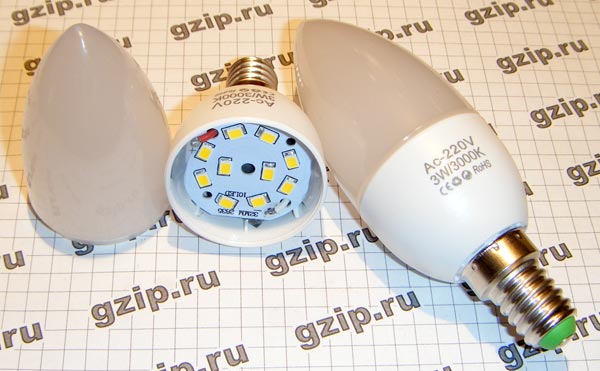
Repair of LED lamp series "LLC" E14 3W1 M1
This lamp is similar to an incandescent lamp. The first thing you can notice is a wide metal ring.
I proceeded to disassemble the lamp. The first step was to remove the cover. As it turned out, it was planted on the base with an elastic compound. After I took it off, I realized that it was in vain.
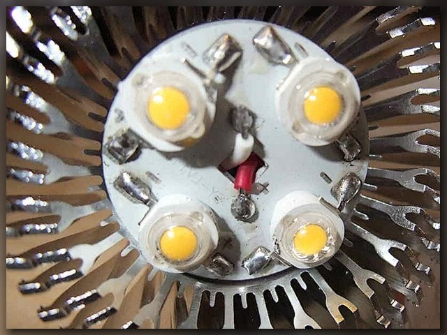
In the lamp was 1 LED, whose power was 3.3 watts. It could be checked from the plinth.
Dismantling and modification of Chinese LED lamps
On our website there are enough publications devoted to light sources. These are, first of all, incandescent lamps; Here we have found a solution, how to protect them from burnout and extend the service life. Perhaps, they still remain the most massive source of light, and the reason here is not only in accessibility, but also in the fact that the spectrum of their radiation is most pleasing to the eye. In addition to conventional light bulbs, the so-called "energy-saving" is popular - compact fluorescent lamps. We gave a description of the methods of repair and refinement, which also increase the service life. However, LED light sources should also be considered as gaining popularity.
The LED lamp consists of several LEDs (or lED matrix) with the power circuit, enclosed in the base. Proper power LEDs - the whole science, the benefit of the drivers of mains power is invented abound, from specialized microcircuits to simple circuits on two transistors. However, manufacturers very rarely use the achievements of circuitry and modern electronics, preferring to feed LEDs on a habit - through a ballast (quenching) capacitor.
For the study were purchased three LED lamps with a power of 3W Chinese made at a price of 35 rubles apiece.
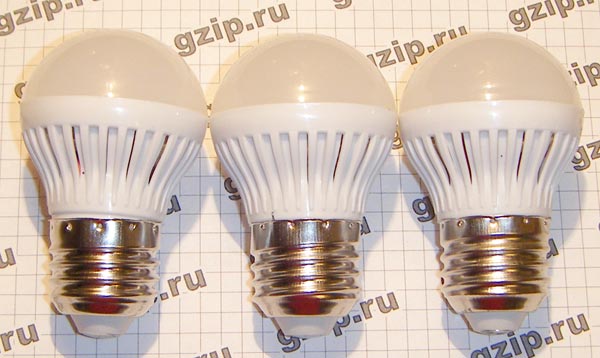
The body is made of plastic, the diffuser in the form of a hemisphere - also plastic, fastens without glue, just snaps. To disassemble the LED lamp, it is enough to pull the diffuser in a circle and disengage it from the lamp body. In this case, the circuit board with the parts is released.
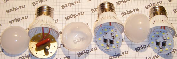
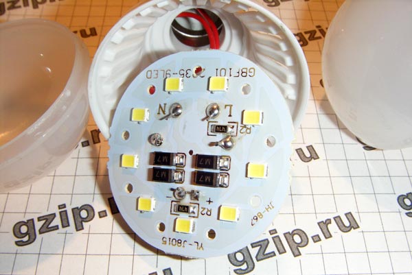
In two lamps of three there is not a single wire, in the rest the installation is more or less neat. The quenching capacitor with the marking 824 is at 820nF (0.82μF), 400V. 9 LEDs of a size similar to 3528, only thinner, connected in series. The bridge is made up of four diodes with the M7 marking.
One such lamp is very weak. At a lamp power of 3W, its light should be comparable with an incandescent lamp with a power of 20-25W. These lamps shine more dimly, which, as it were, hints at the need for measurement, which will soon be done, along with the need to work out whether there is a significant current surge when switching on, are the LEDs working, as they say, "with a crossover"?
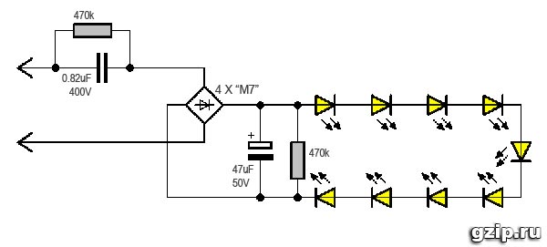
The LED lamp circuit is simple. As already mentioned, the LEDs are powered via a suppression capacitor.
Simulation shows that the current flows through the LEDs 32mA, the total voltage drop on the chain of nine LEDs is 26V, so the power consumption is 0.8W, which is three times less than the declared one.
These lamps are sold as three-shelf. Of course, their real power is three times less. In each lamp there are 10 LEDs 2835. Judging by the datasheets, these LEDs allow a current of up to 150 mA with a good heat dissipation. In this particular case, the whole thing is fed through a ballast capacitor with a capacitance of 0.82 μF and a series-connected resistor of 100 Ω. Closure of the resistor does not significantly affect the brightness of the glow. Lamps shine very dimly.
Disassembled by a simple tilt of the matte scatterer to the side. The LED board is fixed with silicone adhesive.
The following alteration was planned: to increase the capacity of the ballast capacitor in order to increase the current. For verification, a capacitor with a capacitance of 1.5 μF was installed. At the same time, the aluminum substrate of the LEDs was excessively heated. Therefore, the completion of these lamps was not possible.
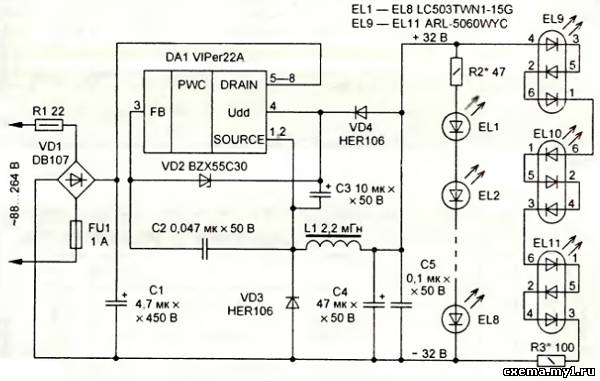
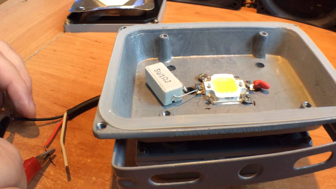
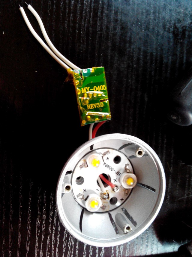
The following lamps are more honest products of Uncle Liao. The lamp is designed to power 12 volts (halogen power units). The case is at the same time a radiator made of honest aluminum.
Lamps are made on the basis of LEDs of 1 watt power, connected in series. Inside the cap there is an ultra-compact stabilizer that is unknown, which (attention!) Does not work. The brightness of the glow of the lamps varies depending on the supply voltage. And this despite the fact that under a heat-shrinkage in one of the lamps there is a famous MC34063 and XL6001 in another.
It is sorted by unscrewing the top and bottom parts.
Possible rework: remake under 220 volts and the "human" cap. This requires the redesign of the lamp design.
Modification of large corn. The lamps themselves are sorted out simply by removing the plastic ring on the end. It is fixed by means of small rods, some of which can be glued. They will have to be torn off. When the ring is removed, a round pad with LEDs will be released. Inside the lamp is a small board with a capacitor ballast, on which an electrolytic capacitor with a capacity of 4.7 μF is installed. This capacity is clearly not enough for a given lamp power, resulting in a flicker that is not noticeable to the eye. There is another, not obvious, drawback: the low capacity of this electrolyte is an insufficient load for condenser ballast at the beginning of work. As is known, a discharged capacitor has a zero resistance and, when the lamp is switched on, a voltage jump occurs, which can easily be burned by an LED. To protect against this unpleasant phenomenon, a larger capacitor should be installed, which will provide the necessary voltage drop-out when switching on or shunt the LEDs with a zener diode. The second variant is more complicated (it is still necessary to find a zener diode for a relatively high voltage) and does not eliminate flickering, so an obvious improvement is the installation of an electrolytic capacitor of greater capacity.
Initially, the board does not get, because is connected by short wires to the lamp socket. Pulling it out as much as possible, we unsolder the wiring. This is quite possible to do. We solder the capacitor to 4.7 uF and install in its place a more capacious, in this case - at 68 uF 450V. The location inside the lamp allows you to install it from the back of the board. We do not set the stabilitron yet - we drive the lamp like this.
Is going all the way back. It should also be remembered that a lamp with a capacitor ballast is galvanically connected to the network and represents a hazard. Therefore, it will not be superfluous to paste or draw the appropriate notation to avoid touching the live parts. Actually, almost the whole lamp - and there are such parts. When installing or removing, keep it very carefully, behind the plastic ring.
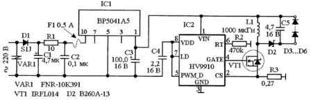
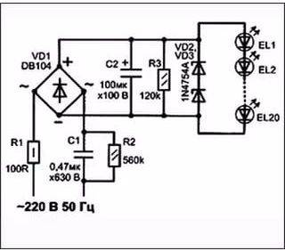
Today in the article we will consider a scheme how to convey energy saving light bulb under a LED lamp powered by 220 volts.
So, after disassembling and extracting from it a completely workable converter, the details of which will still serve us for further designs - take at least excellent high-voltage transistors MJE13003,13001; a symmetrical DB3 dinister for a power regulator, or diodes IN4007 (700V 1A), we have a good case with a base and six holes under ... of course the large LEDs are F10mm. It is them, not the standard 5mm, that I recommend for use in LED lamps, flashlights, etc. At a price somewhat higher (0.5 ye) than conventional LEDs, they give significantly greater brightness at the same supply current - about 20mA.
All elements of the LED lamp are mounted on a circle made of double-sided foil-coated fiberglass. On the one hand, we cut out sections for soldering a chain of light-emitting diodes, and on the other hand for elements of transformerless power supply 18V 25mA. This is how much this LED lamp requires.
It's easier and quicker not to etch a printed circuit board, but to cut through the tracks with a cutter made from a hacksaw blade. I did it. So how do I waste time on etching it. Let's do it faster.
To obtain the desired supply voltage of the LEDs, two variants of the rectifier circuits can be used:
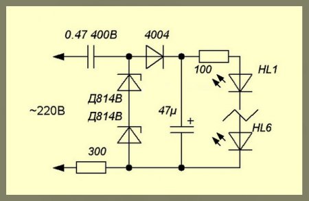
On this, which is simpler, having saved three diodes, we lose almost twice the current. And to compensate, you will have to increase the capacity of 0.47 to 1 mkF. Therefore, I made a choice in favor of such a transformerless rectifier:
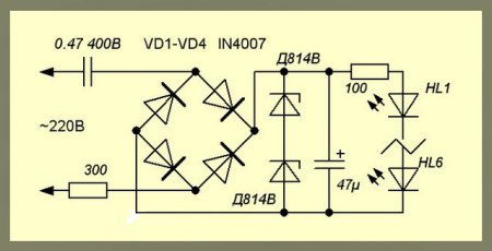
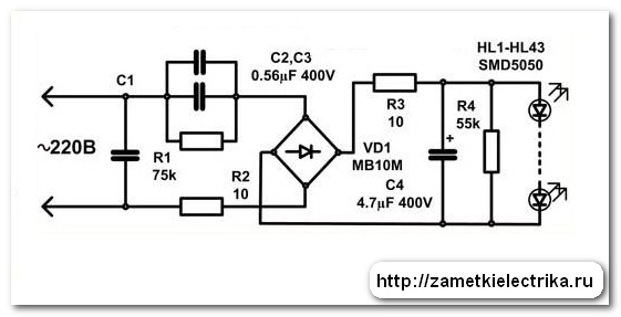
Here, a 300 ohm resistor protects against surges and simultaneously acts as a fuse. We take its power to 0.25 watts. Two zener diode D814B are connected in series and form one zener diode for a voltage of about 20V. If you have ready for 19-25V - forward, you can put it one. The 47μF capacitor smooths the flicker and creates additional protection for the LEDs from impulse surges when the lamp is turned on. A 100 ohm resistor finally sets the total current through a line of self-made LEDs LED Bulb for home.
We fix the hot glue round shawl, close the lid, so that the LEDs protrude from it halfway, and everything - the homemade LED lamp is ready. Of course, it can not compete in brightness with CFL. But in terms of its economy, it will make an economical energy saving - like Belka Strelka. When the power consumption is 18V x 0.025A = 0.4 watts per hour, even if it is never turned off at all, it will eat only 0.4 x 24 x 365 = 4 kW of energy per year. It is worth it at the level of one travel in public transport. Therefore, if constant illumination of the corridor, workplace, duty room, etc. is required, this will be an ideal option.
LED lamps are increasingly used in everyday life. They are used for lighting and lighting, emphasize the details of the interior. Of particular importance is the LED lamp circuit for 220 V, specifications which is much superior to other types of light sources.
Elements of LED lamp
The standard LED lamp consists of the following elements:
- The main external parts are the diffuser and the plinth.
- LEDs installed on the board. The whole design is called. cluster.
- Radiator.
- LED power source - driver.
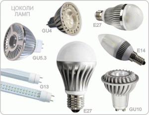
In most lamps, standard socles of the E27 type are used. Its attachment to the body occurs by point depressions applied along the circumference. To remove the base of the recesses drill out or cut with a hacksaw.
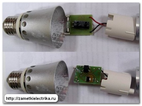
A red wire is connected to the central contact of the cap. The black wire is soldered to the thread. Both conductors have a very short length and in case of possible lamp repair it is necessary to have a stock for building up. After removing the cap, a hole is opened in the diffuser, through which the driver is clearly visible. Its attachment to the body is carried out by silicone, and its extraction is possible only through the diffuser.
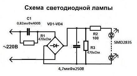
Power cluster, which is an LED board, is implemented using the driver. Under its action, an AC voltage of 220 volts is converted into d.C.. The drivers have parameters such as output current and power.
Thus, the interaction of all elements ensures a stable and uninterrupted operation of the entire lamp. The failure of at least one of them will cause a failure in the operation of the entire system.
LED Power Supply Circuits
Most simple circuit is performed using a resistor that acts as a limiter lED current. The normal operation of the circuit in this case depends only on the right choice resistance of this resistor. This food is mainly used when you need to do lED backlight in the switch.
More complex circuits are performed using a diode bridge. From its output, the rectified voltage is applied to the LEDs connected in series. Smoothing of the ripples of the rectified voltage is carried out using an electrolytic, diode bridge installed at the output.
The main advantages of both schemes are their low cost, small size and fairly simple repairs. Nevertheless, they have a very low efficiency and a high coefficient of ripple.
Perfect power sources - drivers
The newest LED lamps are equipped with drivers based on a pulse converter. They have a high efficiency and a minimum level of ripple. However, their cost is much higher than the previously considered simple options.
To attach the driver to the body, a silicone paste is used. To gain access to this element, the diffuser is first sawed off, and then the LED board is removed. Power supply for 220 volts is done with the help of wires of red and black color from the lamp socket. On the LED board, the power is supplied by colorless conductors.
The driver can work steadily when the mains voltage drops from 85 to 265 volts. In addition, the 220V LED lamp circuit provides protection against short circuits, as well as the presence of electrolytic capacitors, ensuring operation at high temperatures, up to 105 degrees.
For the manufacture of lamp housings, aluminum is used and a special plastic that dissipates heat is good. Due to the qualitative heat removal, the life of the main elements of the lamp increases to 40 thousand hours. More powerful lamps are equipped with radiators attached to the LED board with a layer of thermal paste.