Antipyretics for children are prescribed by a pediatrician. But there are situations of emergency care for fever, when the child needs to give the medicine immediately. Then the parents take responsibility and apply antipyretic drugs. What is allowed to give to infants? How can you bring down the temperature in older children? Which medications are the safest?
Well, as promised - the second article, which is devoted to the system of protection against reverse polarity, which has found wide application in industrial and home-made chargers. This option was chosen as particularly simple and can be repeated even by a person who has nothing to do with electronics.
To implement such a protection scheme, you only need a diode - just one diode, which will be installed in the forward direction on the plus bus charger.

Such a system is only simple, that for the completion of the charger, it is not necessary to disassemble it at all. To implement this idea, we use the most important function of a semiconductor diode - in the forward direction the diode is open, but if it is connected in the opposite direction, it will be locked.
Consequently, if you suddenly confuse the polarity, then the current simply will not go, no claps, heating and other smoke effects.
But as we know, when the voltage flows through the transition of the rectifier diode, then at the output of the latter there will be a drop in voltage in the region of 0.7 Volts, in order to minimize the drop, we will use the Schottky diodes (with a Schottky barrier) voltage in the region of 0.3-0.4 volts.
The only drawback of such protection is that a fairly large current will flow through the diode, which leads to a heating of the diode.

In order for the diode to be installed on the heat sink. Schottky diodes with high current can be found in computer blocks power supply. The diodes in these blocks are a three-lead diode assembly, in each assembly there are two diodes with a common cathode. It is necessary to select diodes with a current of not less than 15 Amperes per diode. In computer blocks, diodes with currents up to 2 x 30 amperes can be encountered.

First, we need to install the diode on the heat sink, then parallelize the anodes of the diodes, so we connected the two diodes in parallel.
Author; AKA KASSIAN
I wanted to collect something connected with the battery charger. And the very first thing I thought of assembling, it's wired from a polarity reversal to a relay.
But when searching for the necessary scheme on the Internet, I did not find anything similar. And before that I saw it a year ago. He drew a diagram from memory and is ready to share with you.
This device is necessary for protecting your battery and charging from breakage, without letting you mix up the terminals in places, will save you from many problems.
Here is the device circuit from the reverse polarity for the chargers on the relay.
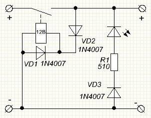
Elements:
R1 = 510
Rel2 = 12V (Any on 12V 10-15A, removed from the former UPS for the computer)
VD1-3 = 1N4007 (I did not find any others).
Although VD3 is not necessary to put, you can put a jumper instead. VD1 from self-inductance of the relay coil.
The device works as follows. When you connect the battery, the remaining charge goes through the relay and closes the contacts, thereby supplying current from the charger to the battery.
If you connect the wrong wires to the battery, VD2 will not let the electricity pass to the relay and charging will not start. And instead of charging, the LED will light, signaling that the charging is not properly connected.
Here is the reverse polarity protection device for the charging device on the PCB.

The reverse polarity protection device for the charger.

Download Sprint-Layout 5.0 printer for the reverse polarity protection device for the charger you can on the site at the source below.
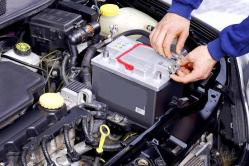
There is a simple charger at home. Ordinary charging, transformer, bridge and wires. Clipped protective films on the clamps, and now how to determine who is where! It was decided to collect the simplest device for protection. I'll say that I've seen something similar before, but I had to make it myself. Just there was a relay with a UPS with 10A contacts.
The scheme works on this principle. When you correctly connect the terminals to the battery, the remaining charge in the battery closes the relay and charging starts, the green LED lights up. When you have confused the terminals, the red LED lights up, indicating that you are not connected correctly. A simple device with only a few parts
Here is the reverse polarity protection scheme
R1-2 = 510
VD1-2 = 1N4148 (But any can be) VD3-4 can be deleted
The relay 12V 10-15A, as said earlier removed from a broken UPS
LEDs any
PCB of the reverse polarity protection device:

We connect as follows:
Z + - plus the charger, there are two of them that you really need, determine yourself, because some relays of this type, close the contacts in different ways
A + - plus battery. Here we connect the positive battery terminal
G is a minus, by its thin wire from a minus of charging to throw
The circuit was welded for 5 minutes, and in the work itself showed quite adequately. I wish good luck with repetition
Update. This scheme was replaced by an even better protection scheme, which, in addition to all the functions inherent in the old scheme, still knows how to determine how long the battery lives. That will save you from such problems as the combustion of the charger due to the old battery killed. You can see my new development
For safe, high-quality and reliable charging of any type of battery, I recommend
With HI. Admin-check
 Did you like this article?
Let's make a gift to the workshop. Throw a pair of coins on a digital oscilloscope UNI-T UTD2025CL (2 channels x 25 MHz). An oscilloscope is a device designed to study the amplitude and time parameters of an electrical signal. It costs 15 490 rubles, I can not afford such a gift. The device is very necessary. With him, the number of new interesting schemes will increase at times. Thanks to everyone who will help.
Any copying of the material is strictly prohibited by me well and copyright .. To not lose this article, throw yourself a link through the buttons on the right
And just ask all the questions through the form below. Do not hesitate guys
n-channel MOSFET + zener diode on 7.2 ... 15V + resistor in a couple of tens of kilo = SECURITY
The problem is, it seems, trivial. And why would anyone at all need to protect any electronic products from the polarity of the power supply?
Alas, in an insidious case there is a thousand and one ways to slip a minus on the device, which you collected and debugged for many days, and it just started working.
Here are just a few examples of potential killers of electronic models, and finished products too:
- Universal power supplies with their universal plugs, which can be connected both with a plus on the internal contact, and with a minus.
- Small power supplies (such boxes on the mains plug) - they are all produced with a plus on the central contact, do not they? NO!
- Any type of connector for power supply without a hard mechanical "key". For example, convenient and cheap computer "jumper" with a pitch of 2.54mm. Or clamps "under the screw."
- How do you like this scenario: the day before yesterday at hand were only black and blue wires. Today I was sure that the "minus" is the blue wire. Chpok - that's a mistake. At first I wanted to use black and red.
- Yes, just if it's been a day to ask - to mix up a pair of wires, or stick them on the contrary simply because the board was holding a super-power cable ...
There will always be people (I'm familiar with at least two such peppers), which look straight into the eyes and say stiffly and peremptorily that they will never commit such stupidity as a polarity of the power source! God is their judge. Maybe, after they assemble and debug several original designs of their own design - they will grow wiser. In the meantime, I will not argue. Just tell you what I use myself.
Stories from life
I was still very young when I had to solder 25 cases of 27. Well, they were good old DIP chips.
Since then, I almost always put a protective diode near the power connector.
By the way, the topic of protection against incorrect polarity of power supply is actual not only at the stage of prototyping.
More recently, I happened to witness the heroic efforts made by my friend to restore the giant laser cutter. The cause of the breakdown was a grief-technician, mixed up the power wires of the sensor / stabilizer of vertical displacement of the cutting head. Surprisingly, the circuit itself seems to have survived (it was protected by a diode in parallel). But burned out completely after: amplifiers, some kind of logic, control of servo drives ...

This is perhaps the easiest and safest way to protect the load from polarity reversal of the power supply.
The only bad thing is the voltage drop across the diode. Depending on which diode is applied, it can drop from about 0.2V (Schottky) and up to 0.7 ... 1V - on ordinary rectifier diodes from p-n transition. Such losses can be unacceptable in the case of a battery pack or a stabilized power supply. Also, with relatively large current consumption, power losses on the diode can be highly undesirable.

With this protection option, there is no loss in normal operation.
Unfortunately, in the case of a polarity reversal, the power source is in danger of breaking. And if the power supply is too strong, the diode will burn out first, and then the entire circuit protected by it.
In my practice, I sometimes used such a variant of protection against reverse polarity, especially when I was sure that the power supply has protection against overcurrent. Nevertheless, one day I earned very clear prints on my burnt fingers, touching the voltage regulator's radiator, which I tried to fight against the thick Schottky diode.
p-channel MOSFET - a successful but expensive solution

This relatively simple solution is virtually devoid of shortcomings: a negligible voltage / power drop on the pass-through device in normal operation, and no current in the case of a reverse polarity.
The only problem is where to get quality inexpensive powerful p-channel fETs with an isolated gate? If you know, I will be grateful for the information 😉
Other things being equal, the p-channel MOSFET will always be about three times worse than its n-channel counterparts by any parameter. Usually the same is worse at the same time and the price, and something to choose from: the resistance of the open channel, maximum current, input capacitance, etc. Explain this phenomenon about three times the mobility of holes, rather than electrons.
n-channel MOSFET - best protection
To get a powerful low-voltage n-channel CMOS transistor these days is not difficult, they sometimes can get hold of even completely free (about this - later;). So to ensure a negligible drop on the open channel for any imaginable load currents is a trifle.
N-channel MOSFET + zener diode on 7.2 ... 15V + resistor in a couple of tens of kilo = SECURITY
Just as in the scheme with a p-channel MOSFET, if the source is incorrectly connected, both the load and the unlucky source are out of danger.
The only "flaw" that the meticulous reader can see in this protection scheme is that the protection is included in the so-called. earth wire.
It really can be inconvenient if a large system with an earth "star" is being built. But in this case, you just need to provide the same protection in the immediate vicinity of the power supply. If this option does not work, there are certain ways to find such a complicated system either by providing unique power connectors with reliable mechanical keys or by building a "constant" or at least "ground" without connectors.
Caution: static electricity!
We have all been warned many times that field-effect transistors are afraid of static discharges. It's true. Usually the shutter can withstand 15 ... 20 Volts. A little higher - and the irreversible destruction of the insulator is inevitable. In this case, there are cases when the field worker is still working, but the parameters are worse, and the device can refuse at any time.
Fortunately (and unfortunately) powerful field effect transistors have large gate capacitances - the rest of the crystal: from hundreds of picofarads, to several nanofarads and more. Therefore, the discharge of the human body is often tolerated without problems - the capacitance is large enough that the clogging charge does not cause a dangerous increase in voltage. So when working with powerful field workers it is often enough to observe minimal caution in the sense of electrostatics and everything will be fine 🙂
I'm not alone
What I am describing here is, without doubt, a well-known practice. That's only if those developers of the military industry had a habit of publishing their schematic solutions in blogs ...
Here's what I found on the web:
\u003e\u003e I believe it is pretty well standard practice to use an N-channel
\u003e\u003e MOSFET in the return of lead of military power supplies (28V input).
\u003e\u003e Drain to supply negative, source to the negative of the PSU and
\u003e\u003e The gate is driven by a protected derivative of the positive supply.
Where to get MOSFETs practically for free
look to me a little later - will be an article 😉
Application examples
Simple with protection from reverse polarity supply:

Successful eksperementov!
Were you interested? Write me!
Ask, offer: in the comments, or in a personal. Thank you!
All the best!
Sergey Patrushin.