Antipyretics for children are prescribed by a pediatrician. But there are situations of emergency care for fever, when the child needs to give the medicine immediately. Then the parents take responsibility and apply antipyretic drugs. What is allowed to give to infants? How can you bring down the temperature in older children? Which medications are the safest?
It is known that the LED in the operating state transmits current in only one direction. If it is connected in an inverted way, then the direct current through the circuit does not pass, and the device does not light up. This is because, in its essence, the device is a diode, it's just that not every diode can light up. It turns out that there is a polarity of the LED, that is, it senses the direction of the current and works only for a certain direction.
Determine the polarity of the device according to the scheme will not be difficult. The LED is indicated by a triangle in the circle. The triangle always rests on the cathode ("-" sign, transverse dash, minus), the positive anode is on the opposite side.
But how to determine the polarity, if you hold the instrument in your hands? Here is a small bulb with two leads-wiring. To which wiring to connect plus a source, and to what minus to the circuit earned? How correctly to establish resistance where plus?
Define visually
The first way is visual. Suppose you need to determine the polarity of a completely new LED with two leads. Look at his legs, that is conclusions. One of them will be shorter than the other. This is the cathode. Remember that this cathode is possible by the word "short", because both words begin with the letters "k". Plus will correspond to that conclusion, which is longer. Sometimes, it's true, the polarity is difficult to identify by eye, especially when the legs are bent or have changed their sizes as a result of the previous installation.
Looking at the transparent case, you can see the crystal itself. It is located as if in a small cup on a stand. The output of this stand will be a cathode. From the side of the cathode you can also see a small notch, as if a cut.
But not always these features are noticeable in the LED, as some manufacturers deviate from the standards. In addition, there are many models made on a different basis. On complex designs, today the manufacturer puts the "+" and "-" icons, mark the cathode with a dot or a green line, so that everything is perfectly clear. But if there are no such marks for some reason, then electrical testing comes to the rescue.
Apply the power supply
A more effective way to determine the polarity is to connect the LED to a power source. Attention! Choose a source whose voltage does not exceed the allowable voltage of the LED. You can build a homemade tester using a conventional battery and a resistor. This requirement is due to the fact that when the connection is re-connected the LED can burn out or deteriorate its light characteristics.
Some say that they connected the LED and so and so, and it did not spoil it. But the whole point is in the limiting value of the reverse voltage. In addition, the light bulb may not immediately go out, but its operation time will decrease, and then your LED will not work 30-50 thousand hours, as indicated in its characteristics, but several times less.
If the power of the battery for the LED is not enough, and the device does not shine, as you connect it, you can connect several elements to the battery. We remind you that the elements are connected in series plus to minus, and minus to plus.
Using a multimeter
There is a device called a multimeter. It can be successfully used to find out where to connect plus, and where minus. This takes exactly one minute. In the multimeter select the resistance measurement mode and touch the probes to the LED contacts. The red wire indicates the connection to the plus, and the black wire to the negative. It is desirable that the touch was short-lived. When the device is turned back on, the device will not show anything, but when direct inclusion (plus plus, and minus to minus) the device will show a value in the region of 1.7 kOhm.
You can also turn the multimeter on to check the diode. In this case, with direct connection light will glow.
This method is most effective for light bulbs that emit red and green light. The LED giving blue or white light is rated for a voltage greater than 3 volts, so it will not always light up when connected to a multimeter, even with the correct polarity. From this situation, you can easily exit, if you use the mode of determining the characteristics of transistors. On modern models, such as the DT830 or 831, it is present.
The diode is inserted into the slots of a special pad for transistors, which is usually located at the bottom of the device. A part of PNP is used (as for transistors of the corresponding structure). One leg of the LED is shoved into connector C, which corresponds to the collector, the second leg to connector E, corresponding to the emitter. The light will light up if the cathode (minus) is connected to the collector. Thus, the polarity is defined.

LED - a semiconductor optical device that transmits electricity at forward direction. When connecting an inversion current in the circuit will not, and, of course, there will be no glow. To avoid this, it is necessary to observe the polarity of the LED.
The LED in the diagram is indicated by a triangle in a circle with a cross bar - it is a cathode that has the sign "-" (minus). On the opposite side is the anode, which has the sign "+" (plus).

In the wiring diagrams, pinout (or pinout) of the pins must be present to identify all junction contacts.
How to determine the polarity of a diode, holding a tiny light bulb in your hands? After all, for the correct connection you need to know where it has a minus, and where plus. If the pinout of the pins is traced, the circuit will not work.
Visual method for determining polarity
The first way to determine is visual. The diode has two conclusions. The short leg is a cathode, the anode of the LED is always longer. It is easy to remember, because there is an initial "k" in both words.

When both outputs are bent or the device is removed from another board, their length can be difficult to determine. Then you can try to see in the body of a small crystal, which is made of a transparent material. It is located on a small stand. This conclusion corresponds to the cathode.
Also, the cathode of the LED can be determined by a small notch. In new models lED strip light and lamps use semiconductors for surface mounting. The existing key in the form of a bevel indicates that it is a negative electrode (cathode).
Sometimes LEDs are marked with "+" and "-". Some manufacturers mark the cathode as a dot, sometimes a green line. If there is no mark or it is difficult to discern because the LED was removed from another circuit, you need to test.
Testing with a multimeter or battery
Well, if you have a multimeter at hand. Then the polarity of the LED will be determined in one minute. By selecting the ohmmeter mode (resistance measurement), it is not difficult to perform the following action. Applying the test leads to the legs of the LED, the resistance is measured. The red wire should be connected to the plus, and the black wire to the negative.
If properly turned on, the device will give a value of approximately 1.7 kOhm, and glow will be observed. When you turn it back on, the multimeter will display an infinitely large value. If the check shows that on both sides the diode shows little resistance, then it is knocked out, and it should be disposed of.


In some devices there is a special mode. It is designed to check the polarity of the diode. Direct activation will be signaled by a diode illumination. This method is suitable for red and green semiconductors.
The blue and white LEDs give an indication only at a voltage of more than 3 volts, so you can not achieve the desired result. To test them, you can use multimeters such as DT830 or 831, which provides a mode for determining the characteristics of transistors.
Using the PNP-part, one LED pin is inserted into the collector socket, the second - into the emitter hole. When direct connection an indication appears, inversion switching will not give such an effect.
How to determine the polarity of the LED if there is no multimeter at hand? You can resort to a regular battery or battery. To do this, you need any more resistor. This is necessary to protect the LED from breakdown and failure. A series-connected resistor, whose resistance value should be approximately 600 ohms, will allow limiting the current in the circuit.

And a few more tips:
- if the polarity of the LED is known, then the reverse voltage can not be applied to it. Otherwise there is a probability of breakdown and failure. With proper operation, the LED will serve properly, as it is durable, and its housing is well protected from moisture and dust;
- some types of LEDs are sensitive to static electricity (blue, purple, white, emerald). Therefore, they must be protected from the influence of "statics";
- when testing the LED with a multimeter, it is desirable to perform this action quickly, touching the terminals must be short-lived, in order to avoid diode breakdown and failure of the diode.
Indicator and super-bright LEDs are widely used in industrial equipment and in amateur radio designs. Like any other diodes, LEDs have two outputs - the anode and the cathode (plus and minus). Therefore, they must be connected in accordance with the polarity. You can determine the polarity of the LED in several ways:
- by measurements;
- in appearance (visually);
- connection to the power supply;
- from technical documentation.
Virtually all professionals and most radio amateurs at hand have digital or arrow multimeters. With their help, you can easily determine the polarity of a semiconductor diode, check its performance. Measurements should be carried out in the ohmmeter mode.
Many modern multimeters have a special mode - a "diode test".
To determine the polarity, the test leads are connected to the diode and monitored by the instrument. If the instrument shows an "infinite" resistance, then the probes should be swapped. If the multimeter shows some finite resistance value, this means that the device is connected in accordance with the polarity, and we determined where the LED has plus and minus.
There is one important nuance. For some switchgears, the polarities of the probes in the voltage measurement mode and in the ohmmeter mode do not match.
This feature is, for example, old testers TL-4M. Therefore, it is desirable to check whether there are any discrepancies in the polarity of the tester in different modes of measurement using another instrument or a voltmeter constant voltage.
Multimeter can also be used to determine the polarity. The procedure is the same as for determining the plus and minus of an ordinary diode. With a working LED and its correct connection, it can even start to glow. However, this method of determining the polarity does not always work. The fact is that the voltage drop of the open LED can be 1.5 - 3.2 and more volts. This is much larger than that of a conventional semiconductor diode.
The magnitude of the voltage drop depends on the color and power of the light-emitting diode. Testers with low voltage power supply do not have enough voltage on their terminals to open the LED. Such measuring devices can not be performed.
How to determine the polarity in appearance
There are many types of LED enclosures. Widely distributed light-emitting diodes in cylindrical bodies with a diameter of 3, 5 or more millimeters. Many SMD LEDs are available for surface mounting, which differ in both the type of housing and the size of the crystals. Powerful super-bright LEDs are located on the heat sinks and have planar flat terminals. Experienced professionals can easily determine the purpose of the findings in appearance.
The easiest way to determine the polarity of high-power LEDs. As a rule, their conclusions are marked with the "+" and "-" signs.

Not bad with the LEDs in the cylindrical bodies. They have a polarity can be determined by several features. For example, inside the light-emitting diode housing, two electrodes having different areas can be considered. At the cathode, the area of the electrode is much larger. This electrode is a minus. Another sign that the cathode of a cylindrical led can be determined is the bevel on the skirt of the instrument. The new terminals have different lengths. A longer output suggests where the plus of the LED (anode) is.
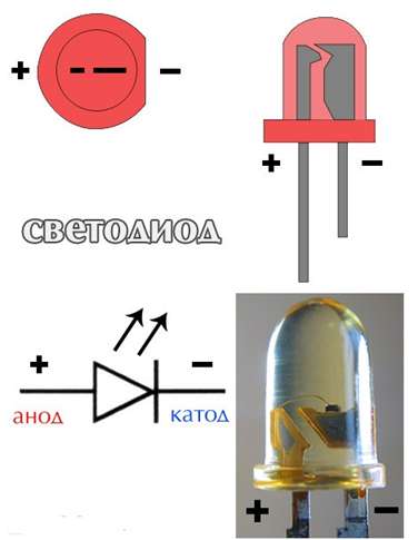
LEDs for surface mounting also have distinctive signs of pin assignment. Many SMD LEDs have a special bevel (key) on one of the corners. The key indicates a minus (cathode).

On the cases of some types of SMD LEDs, special symbols are used to determine the polarity of the device. Some of them are shown in the photo.

Determination of polarity by power supply
The most obvious way to determine the polarity of the LED is to connect to a voltage source. This method allows you to check the serviceability of the LED and determine its polarity.
To carry out the "experiment" you need a constant voltage source. They can be a power supply or a rechargeable battery. It is convenient to use a laboratory power supply with a smooth voltage regulation and a DC voltmeter.
The LED should be connected to the power supply and gradually raise the voltage. When the correct connection it should start to glow. If the LED does not light up when 3 to 4 volts is reached, the polarity of the connection should be changed and the experiment repeated. When lighting the LED, do not continue to increase the voltage; it can burn.
Instead of a regulated power supply, you can use any 4.5 - 12 volt battery. As a battery, you can use several 1.5 volt elements connected in series, the battery from a cell phone or car.
It is not possible to directly connect the LED to the battery. It can break down.
To check the operation in series with the LED, you need to connect a current-limiting resistor. Resistor resistance for low-power light-emitting diode can be from 680 Ohm to several kOhm. For high-power LEDs, a resistor of several tens of Ohms is suitable.

Determination of polarity according to technical documentation
Exhaustive information about the LEDs can be obtained from the technical documentation of the manufacturer's factory. It reflects data on the mass and dimensions of the led, its pinning and electrical parameters. At large deliveries such documentation is necessarily available in accompanying documents.
Unfortunately, retailers who sell retailers can not always provide interesting data. Fortunately, knowing the brand of the light-emitting device, information about the appointment of its conclusions can always be found on the Internet.
Outcomes
We have considered several ways how to determine the plus and minus of the LED. They can be used one by one, or you can double-check the result in several ways. After all, each of them is not ideal. Visually and even more so on technical documentation it is impossible to judge the working capacity of this LED instance. Using a tester it is difficult to call a powerful super-bright light-emitting diode. Checking by applying voltage gives an accurate result, but requires precautions.
It is known that the LED in the operating state transmits current in only one direction. If it is connected in an inverted way, then the direct current through the circuit does not pass, and the device does not light up. This is because, in its essence, the device is a diode, it's just that not every diode can light up. It turns out that there is a polarity of the LED, that is, it senses the direction of the current and works only for a certain direction.
Determine the polarity of the device according to the scheme will not be difficult. The LED is indicated by a triangle in the circle. The triangle always rests on the cathode ("-" sign, transverse dash, minus), the positive anode is on the opposite side.
But how to determine the polarity, if you hold the instrument in your hands? Here is a small bulb with two leads-wiring. To which wiring to connect plus a source, and to what minus to the circuit earned? How correctly to establish resistance where plus?
Define visually
The first way is visual. Suppose you need to determine the polarity of a completely new LED with two leads. Look at his legs, that is conclusions. One of them will be shorter than the other. This is the cathode. Remember that this cathode is possible by the word "short", because both words begin with the letters "k". Plus will correspond to that conclusion, which is longer. Sometimes, it's true, the polarity is difficult to identify by eye, especially when the legs are bent or have changed their sizes as a result of the previous installation.
Looking at the transparent case, you can see the crystal itself. It is located as if in a small cup on a stand. The output of this stand will be a cathode. From the side of the cathode you can also see a small notch, as if a cut.
But not always these features are noticeable in the LED, as some manufacturers deviate from the standards. In addition, there are many models made on a different basis. On complex designs, today the manufacturer puts the "+" and "-" icons, mark the cathode with a dot or a green line, so that everything is perfectly clear. But if there are no such marks for some reason, then electrical testing comes to the rescue.
Apply the power supply
A more effective way to determine the polarity is to connect the LED to a power source. Attention! Choose a source whose voltage does not exceed the allowable voltage of the LED. You can build a homemade tester using a conventional battery and a resistor. This requirement is due to the fact that when the connection is re-connected the LED can burn out or deteriorate its light characteristics.

Some say that they connected the LED and so and so, and it did not spoil it. But the whole point is in the limiting value of the reverse voltage. In addition, the light bulb may not immediately go out, but its operation time will decrease, and then your LED will not work 30-50 thousand hours, as indicated in its characteristics, but several times less.
If the power of the battery for the LED is not enough, and the device does not shine, as you do not connect it, you can connect several elements to the battery. We remind you that one hundred elements are connected consecutively plus to a minus, and a minus to plus.
Using a multimeter
There is a device called a multimeter. It can be successfully used to find out where to connect plus, and where minus. This takes exactly one minute. In the multimeter select the resistance measurement mode and touch the probes to the LED contacts. The red wire indicates the connection to the plus, and the black wire to the negative. It is desirable that the touch was short-lived. When the device is turned back on, the device will not show anything, and when switched on (plus to plus, and minus to minus), the device will show a value in the region of 1.7 kOhm.
You can also turn the multimeter on to check the diode. In this case, when switched on directly, the LED light will be on.
This method is most effective for light bulbs that emit red and green light. The LED giving blue or white light is rated for a voltage greater than 3 volts, so it will not always light up when connected to a multimeter, even with the correct polarity. From this situation, you can easily exit, if you use the mode of determining the characteristics of transistors. On modern models, such as the DT830 or 831, it is present.
The diode is inserted into the slots of a special pad for transistors, which is usually located at the bottom of the device. A part of PNP is used (as for transistors of the corresponding structure). One leg of the LED is shoved into connector C, which corresponds to the collector, the second leg to connector E, corresponding to the emitter. The light will light up if the cathode (minus) is connected to the collector. Thus, the polarity is defined.
Chapter 3 - Diodes and Rectifiers
Both for fans and for electronics professionals, the ability to determine the polarity (where the cathode, and where the anode) and the performance of the diode is very important. Since we know that a diode is, in fact, no more than a one-way valve for electricity, it is likely that we can test its unidirectional nature with an ohmmeter measuring resistance to direct current (battery-powered) as shown in the figure below. When connecting a diode in one way, the multimeter should show a very low resistance in the figure (a). When connecting the diode in another way, the multimeter should show a very large resistance in the figure (b) (some models of digital multimeters in this case show "OL").
Determination of the polarity of the diode: (a) The low resistance indicates a forward bias, the black probe is connected to the cathode, and the red probe to the anode. (b) The change of the probes in places shows a high resistance indicating a reverse bias.
Of course, in order to determine which diode output is the cathode and which is the anode, you must know exactly which output of the multimeter is positive (+) and which is negative (-) when "resistance" or "Ω" is selected . In most digital multimeters I've seen, the red pin is used, as positive, and black as negative, in accordance with the agreement on color marking electronics.
One of the problems with using an ohmmeter to check a diode is that we only have a qualitative value, not a quantitative one. In other words, an ohmmeter tells you just which direction the diode conducts; The low resistance value obtained during measurement is useless. If the ohmmeter shows a value of "1.73 ohms" with a direct bias of the diode, then the number 1.7 Ohm does not represent for us, as for technicians or schematics designers, any really useful quantitative evaluation. It does not represent either a direct voltage drop or a resistance value of the semiconductor material of the diode itself; this number depends on both values and will vary depending on the specific ohmmeter used for the measurement.
For this reason, some manufacturers of digital multimeters equip their measuring instruments with a special "diode check" function, which shows a real direct voltage drop across the diode in volts, rather than the value of "resistance" in ohms. These meters work by passing a small current through the diode and measuring the voltage drop between the two probes (figure below).

The direct voltage reading thus obtained with a multimeter is usually less than the "normal" drop of 0.7 volts for silicon diodes and 0.3 volts for germanium diodes, since the current provided by the meter is rather small. If you do not have a multimeter with a diodes check function, or you would like to measure a direct voltage drop across a diode with a different current, you can assemble a circuit from a battery, a resistor and a voltmeter.

Connecting the diode in this test circuit in the opposite direction will simply result in the voltmeter showing the full voltage of the battery.
If this circuit has been designed to provide a constant (or almost) current through the diode, despite the changes in the forward voltage drop, it can be used as the basis for a tool measuring the temperature: the voltage measured on the diode will be inversely proportional to the diode junction temperature. Of course, the current through the diode should be minimal to self-heating (a significant amount of power dissipated by the diode), which could interfere with the measurement of temperature.
Remember that some digital multimeters equipped with the "diode check" function, when operating in the normal "resistance" (Ω) mode, can produce a very low test voltage (less than 0.3 volts), too low for a full collapse (compression) of the depletion region PN transition. The bottom line is that the "diode test" function should be used here for testing semiconductor devices, and the "resistance" function for the rest. Using a very low test voltage to measure resistance facilitates the process of measuring the resistance of non-semiconductor components connected to semiconductor components, since the transitions of the semiconductor component will not be shifted by such low voltages in the forward direction.
Consider an example of a resistor and a diode connected in parallel and soldered to the printed circuit board. As a rule, before measuring the resistance of the resistor, it would be necessary to remove it from the circuit (disconnect the resistor from the remaining components), otherwise any parallel components will affect the readings. When using a multimeter that outputs very low test voltage in resistance mode to the test leads, the PN diode transition will not be energized enough to be biased in the forward direction, and therefore the diode will pass a small current. Therefore, the meter "sees" the diode as a break, and shows the resistance of the resistor only (figure below).

If you use such an ohmmeter to check the diode, it will show a very high resistance (a lot of megaohm), even if you connect the diode in the "right" (for direct displacement) direction (figure below).

The magnitude of the reverse diode voltage is not measured so easily, since the excess of the reverse voltage on an ordinary diode leads to its destruction. Although there are special types of diodes designed for "reverse" bias without damaging the diode (so-called zener diodes), which are tested in the same source / resistor / voltmeter circuit, provided that the voltage source provides enough voltage for the diode to go into region of breakdown. For more information, see one of the following articles in this chapter.
Let's sum up the results
- The ohmmeter can be used for a qualitative evaluation of the diode's operability. When connecting a diode in one direction, a low resistance should be obtained, and a connection in the other direction should have a very high resistance. When using an ohmmeter for this purpose, be sure to know which test probe is positive and which is negative!
- Some multimeters have a "diode check" function that displays the actual direct voltage of the diode when it conducts a current. Such measuring devices usually show a slightly lowered value of the forward voltage, compared to the "nominal" value, because of the very small value of the current used for testing.