Antipyretics for children are prescribed by a pediatrician. But there are situations of emergency care for fever, when the child needs to give the medicine immediately. Then the parents take responsibility and apply antipyretic drugs. What is allowed to give to infants? How can you bring down the temperature in older children? Which medications are the safest?
When designing the electric drive, the motor must be selected in such a way that its mechanical characteristics correspond to the mechanical characteristics of the production mechanism. The mechanical characteristics give the interrelation of variables in steady-state regimes.
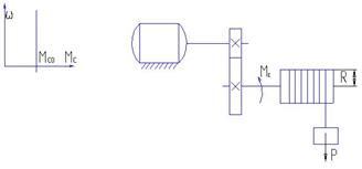
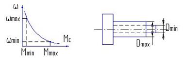
Mechanical characteristic of the mechanism called the relationship between the angular velocity and the moment of resistance of the mechanism, reduced to the motor shaft) ω = f (Mc).
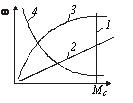
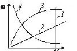
Fig. 1. Mechanical characteristics of mechanisms
Among the variety are several characteristic types of mechanical characteristics of the mechanisms:
1. Characteristic with the moment of resistance, not depending on the speed (straight line 1 in Figure 1). The speed-independent mechanical characteristic is graphically represented by a straight line parallel to the axis of rotation, in this case vertical. Such characteristics are, for example, lifting cranes, winches, piston pumps with a constant feed height, etc.
2. Characteristic with the moment of resistance linearly depending on the speed (straight line 2 in Figure 1). This dependence is inherent, for example, to the drive of a direct current generator with independent excitation, which operates on a constant load.
3. Characteristic with a nonlinear increase in the moment (curve 3 in Fig. Typical examples are the characteristics of fans, centrifugal pumps, propellers. For these mechanisms, the moment Mc depends on the square of the angular velocityω
. This so-called. parabolic (fan) mechanical characteristic.
4. Characteristic with a nonlinearly decreasing moment of resistance (curve 4 in Figure 1). Here the moment of resistance is inversely proportional to the speed of rotation. The power in this case remains constant over the entire operating speed range of the mechanism. For example, in the mechanisms of the main movement of some metal-cutting machines (turning, milling, boring), the moment Mc varies inversely with ω, and the power consumed by the mechanism remains constant.
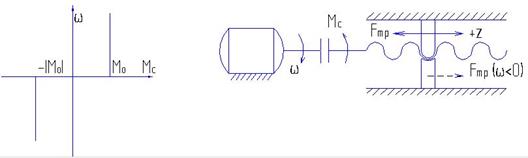
Mechanical characteristic of the electric motor is the dependence of its angular velocity on the torque ω d = f (M). Here it should be borne in mind that the moment M on the motor shaft, regardless of the direction of rotation, has a positive sign - the moment of motion. At the same time, the moment of resistance Mc has a negative sign.
As examples in Fig. 2 shows the mechanical characteristics: 1 - synchronous motor; 2 - independent direct current motor; 3 - a DC motor of series excitation.
![]()
Fig. 2. Mechanical characteristics of electric motors
To evaluate the properties of the mechanical characteristics of the electric drive, the concept of rigidity of the characteristic is used. The rigidity of the mechanical characteristic is determined by expression
β = dM / dω
where d M - change the motor torque; d ω d is the corresponding change in the angular velocity.
For linear characteristics, the value of β remains constant, for nonlinear ones, it depends on the operating point.
Using this concept, the characteristics shown in Fig. 2, can be qualitatively evaluated as follows: 1 - absolutely rigid (β = ∞); 2 - rigid; 3 - soft.
Absolutely rigid characteristic - the engine speed remains unchanged when the engine load varies from zero to nominal. Synchronous motors have this characteristic.
Rigid characteristic - the rotational speed varies slightly when the load changes from zero to nominal. This characteristic has a direct current motor with parallel excitation, as well as an induction motor in the region of the linear part of the characteristic.
Soft characteristic - engine rotation speed varies significantly with relatively small changes in load. Such a characteristic is possessed by a DC motor with series, mixed or parallel excitation, but with an additional resistance in the armature circuit, and also asynchronous with the resistance in the rotor circuit.
For most production mechanisms, asynchronous motors with a squirrel-cage rotor are used, which have a rigid mechanical characteristic.
All mechanical characteristics of electric motors are divided into natural and artificial.
Natural mechanical characteristic refers to the operating conditions of the motor with nominal values of the parameters.
For example, for a motor with parallel excitation, a natural characteristic can be constructed for the case where the voltage at the armature and the excitation current have nominal values, and there is no additional resistance in the armature circuit.
The natural characteristic of an asynchronous motor corresponds to the rated voltage and the rated frequency of the alternating current supplied to the stator of the engine, with the condition that there is no additional resistance in the rotor circuit.
Thus, for each engine, a natural characteristic can be built only one, and artificial - an unlimited number. For example, each new resistance value of the DC motor armature or in the rotor chain of an asynchronous motor has its own mechanical characteristic.
The static mechanical characteristic of the motor called the dependence of speed on the torque of the engine. w = | (M). Almost all motors have the property that their speed is a decreasing function of the motor torque. This applies to all conventional electric motors used in industry, that is, to DC motors of independent, sequential and mixed excitation, as well as to asynchronous brushless and collector AC motors. However, the degree of change in speed with the variation of the torque for different engines is different and is characterized by the so-called rigidity their mechanical characteristics.
Rigidity of the mechanical characteristic of the drive- is the ratio of the increment of torque developed by the electric motor device, with a change in speed, to the corresponding difference in the angular velocities of the electric drive:
![]()
Typically, in working areas, the mechanical characteristics of the engines have a negative rigidity of β<0. Линейные механические характеристики обладают постоянной жесткостью. В случае нелинейных характеристик их жесткость не постоянна и определяется в каждой точке как производная момента по угловой скорости
The rigidity of the mechanical characteristic in the geometric sense is the slope of the mechanical characteristic of the engine.
If you compare characteristics 1 and 2, characteristic 1 is softer, because its inclination is less
DМ 1\u003e DМ 2 Þ b 1\u003e b 2, since and.
The mechanical characteristics of electric motors can be divided into four main categories:
1. Absolutely rigid mechanical characteristic (β = ∞) is the characteristic at which the speed with the change of the moment remains unchanged. Synchronous motors have this characteristic (straight line 1 in Fig. 1).
2. Rigid mechanical characteristic This is a characteristic in which the speed with the change of torque, although it decreases, but to a small extent. A rigid mechanical characteristic is possessed by DC motors of independent excitation, as well as asynchronous motors within the working part of the mechanical characteristic (curve 2 in Fig. 1).
For an induction motor, the stiffness at different points of the mechanical characteristic is different. Between the maximum (critical) values of the moments in the motor Mk, q and the generator Mk, r modes, the characteristic of the induction motor has a relatively high rigidity.
 3. Soft mechanical characteristic is a characteristic in which the speed changes significantly with the change of the moment. Such characteristics are possessed by DC motors of series excitation, especially in the zone of small moments (curve 3 in Fig. 2). For these engines, the stiffness does not remain constant for all points of characteristics.
DC motors of mixed excitation can be assigned to the second or third group, depending on the value of the rigidity of the mechanical characteristic.
4. Absolutely soft mechanical characteristic (β = 0) is a characteristic in which the angular velocity of the engine remains unchanged. Such characteristics are possessed, for example, by direct current motors of independent excitation when feeding them from a current source or when working in closed systems of an electric drive in the mode of stabilizing the armature current (line 4 in Figure 2).
Mechanical characteristics of the working machine Is the dependence of the speed of the working machine on the moment of resistance, which it creates w = | (M c).
The mechanical characteristics describe the load on the electric drive.
Classification of typical loads:
1. The active moment of resistance M c = const
Example: hoist winch drive.
The load is able to activate the mechanism itself, therefore it is called active. The parking brake must be provided for the construction.
2. reactive moment of resistance M c = const (load of the type of constancy of the moment)
Typical for mechanisms such as "dry friction".
M c = M 0 sign (w).
w\u003e 0 Þ M c\u003e 0; w<0 Þ М с <0.
The reactive moment is a reaction to the velocity w.
3. Viscous friction
M c = α BT ω
The moment of resistance is proportional to the speed.
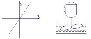
bw is the coefficient of viscous friction.
4. The ventilation moment
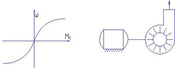
M c = kw 2 sign (w).
Typical for centrifugal fans and pumps.
If the inlet is closed, the load torque will decrease.
P = M c w is the power.
5. Constant power P = const
Where P c = const.
It is often used for the main drives of machine tools (turning, milling, boring, grinding and other machines).
w max ∙ M min = w min ∙ M max = const.
Let's consider turning:
w = const, F p = const.


For planer:
P 1 = v min ∙ F max - working stroke, P 1 = v max ∙ F min - Idling.
P 1 »P 2 = const.
Features of engine selection:
At P 1 = 5 kW we get P dv = 5 ∙ 100 = 500 kW.
Direct selection of the motor from the limit values leads to an overestimate of the installed engine power in D w times, where D w is the speed control range. In fact, engine power can be reduced specifically, by selecting the speed control range.
For DFT, HB is the speed control for excitation currents.
Mechanical characteristic of the engine called the dependence of the rotational speed rotor from the moment on the shaft n = f (M2). Since under load, the idling torque is small, then M2 ≈ M and the mechanical characteristic is represented by the dependence n = f (M). If we take into account the interrelation s = (n1 - n) / n1, then the mechanical characteristic can be obtained by presenting its graphical dependence in the coordinates n and M (Fig.
Fig. 1. Mechanical characteristic of an asynchronous motor
The natural mechanical characteristic of an induction motor corresponds to the main (passport) scheme of its inclusion and the nominal parameters of the supply voltage. Artificial characteristicsare obtained if any additional elements are included: resistors , reactors , capacitors . When the motor is powered by a non-rated voltage, the characteristics also differ from the natural mechanical characteristics.
Mechanical characteristics are very convenient and useful tool for the analysis of static and dynamic modes of the electric drive.
The main points of the mechanical characteristics: critical slip and frequency, maximum torque, starting torque, rated torque.
The mechanical characteristic is the dependence of the torque on sliding, or, in other words, on the number of revolutions:
![]()
From expression 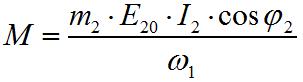 it can be seen that this dependence is very complicated, since, as formulas show)
  and
and 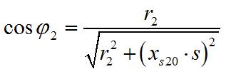 , slip also enters into the expressions for I 2
and cos? 2. The mechanical characteristic of an asynchronous motor is usually given graphically
, slip also enters into the expressions for I 2
and cos? 2. The mechanical characteristic of an asynchronous motor is usually given graphically
The starting point of the characteristic corresponds to n = 0 and s = 1: this is the first instant of starting the engine. Starting torque M n - a very important characteristic of the operational properties of the engine. If M n small, less than the rated operating torque, the engine can only be started idle or with a correspondingly reduced mechanical load.
Denote by M np The counteracting (braking) torque created by the mechanical load on the shaft at which the engine starts. An obvious condition for the possibility of starting the engine is: M n > M np . If this condition is met, the rotor of the motor will move, the number of revolutions of it n will increase, and sliding s to decrease. As can be seen from the image above, the torque of the motor increases from M n to the maximum M m , corresponding to critical slip s kp, therefore, the excess available engine power, determined by the difference in moments M and M np .
The greater the difference between the available motor torque (possible with a given slip in the operating characteristic) M and opposing M np , the easier the startup mode and the faster the motor reaches the steady speed of rotation.
As the mechanical characteristic shows, at a certain number of revolutions (at s = s kp) the available torque of the motor reaches the maximum possible for the given motor (at a given voltage U ) values M t . Further, the motor continues to increase the speed of rotation, but the available torque rapidly decreases. At some values n and s the torque of the motor becomes equal to the counter-torque: the start of the engine is ended, its speed is set at the value corresponding to the ratio:
![]()
This ratio is mandatory for all load conditions of the engine, that is, for all values M np , not exceeding the maximum available engine torque M t . Within these limits, the motor automatically adapts itself to all load fluctuations: if during the engine operation its mechanical load increases, for an instant M np will be more than the moment developed by the engine. The engine speed will start to decrease, and the moment will increase.
The speed of rotation is established at a new level corresponding to equality M and M np . When the load decreases, the process of transition to the new load regime will be reversed.
If the load torque M np will exceed M t , the engine immediately stops, as with further reduction in engine speed the engine torque decreases.
Therefore, the maximum motor torque M t is also called the overturning or critical moment.
If in the moment formula ![]() substitute:
substitute:
then we get:
Taking the first derivative of M by and equating it to zero, we find that the maximum value of the torque comes when:
that is, with such sliding s = s kp , at which the active resistance of the rotor is equal to the inductive resistance
![]()
Values s kp the majority of asynchronous motors lie in the range of 10 - 25%.
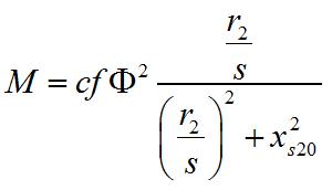
If in the above formula of the moment instead of the active resistance r 2 substitute the inductive by the formula
![]()
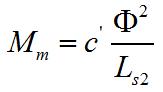
Maximum torque asynchronous motor is proportional to the square of the magnetic flux (and hence the square of the voltage) and inversely proportional to the inductance of the scattering of the winding of the rotor.
When the voltage applied to the motor is constant, its flux F remains almost unchanged.
The inductance of scattering of the rotor chain is also practically constant. Therefore, when the active resistance in the rotor circuit changes, the maximum value of the torque M t It will not change, but will come in at different slips (with an increase in the active resistance of the rotor - for large values of slip).
Obviously, the maximum possible load of the engine is determined by its value M t . The working part of the engine performance lies in a narrow range of speed from n, the corresponding M t , before. When n = n 1 (end point of the characteristic) M = 0, since at synchronous rotor speed s = 0 and I 2 = 0.
The nominal torque determining the value of the rated power of the engine is usually taken to be 0.4-0.6 from M t . Thus, asynchronous motors allow short-time overloads of 2 - 2.5 times.
The main parameter characterizing the operation mode of an asynchronous motor is slip s - the relative difference between the rotor speed of the motor n and its field n o: s = (n o - n) / n o.
The area of the mechanical characteristic corresponding to 0 ≤ s ≤ 1 is the region of the motor regimes, with s< s кр работа двигателя устойчива, при s > s cr is unstable. For s< 0 и s > 1 the motor torque is directed against the direction of rotation of its rotor (respectively regenerative braking and braking by opposing).
A stable portion of the engine's mechanical characteristic is often described the Kloss formula , by substituting into it the parameters of the nominal mode, one can determine the critical slip s cr:
 ,
,
where: λ = M kp / M н - overload capacity of the engine.
Mechanical characteristics according to the directory or catalog data can approximately be constructed on four points (Figure 7.1):
Point 1 - ideal idling, n = n o = 60 f / p, M = 0, where: p - number of pairs of poles of the magnetic field of the engine;
Point 2 - nominal, mode: n = n н, М = М н = 9550 P н / n н, where P н - rated motor power in kW;
Point 3 - critical mode: n = n cr, M = M cr = λ M n;
Point 4 - start mode: n = 0, M = M start = β M N.
When analyzing the operation of the engine in the load range up to M n, and somewhat more, the stable portion of the mechanical characteristic can be roughly described by the straight line equation n = n 0 - BM, where the coefficient "c" is easily determined by substituting the nominal mode parameters n n and M n into the equation.
Stator winding design. Single-layer and double-layer loop windings.
According to the design of the coils, the windings are subdivided into soft coils with coils and coils with rigid coils or coils. Soft coils are made from a round insulated wire. To give the desired shape, they are pre-wound on the templates, and then stacked in isolated trapezoidal grooves (see Figure 3.4, at, gand 3.5, at); phase-to-phase insulating gaskets are installed during the winding process. Then the coils are strengthened in the grooves with the help of wedges or covers, give them the final form (form the frontal parts), bandage the winding and impregnate it. The entire process of making v-type windings can be completely mechanized.
Rigid coils (semi-coils) are made of rectangular insulated wire. The final form is given to them before grouting; at the same time they are superimposed on the body and phase-to-phase insulation. Then, the coils are laid in pre-insulated open or semi-open grooves , strengthen and impregnate.
1. Single-layer windings - most suitable for mechanized laying, since in this case the winding must be concentric and fit into the stator grooves with both sides of the coil simultaneously. However, their use leads to an increased consumption of the winding wire due to the considerable length of the frontal parts. In addition, in such windings it is not possible to shorten the step, which leads to a deterioration in the shape of the magnetic field in the air gap, an increase in additional losses, the appearance of dips in the mechanical characteristic, and an increase in noise. However, because of their simplicity and cheapness, such windings are widely used in small-capacity asynchronous engines up to 10-15 kW.
2. Two-layer windings- allow shortening the winding pitch to any number of tooth divisions, thereby improving the shape of the magnetic field produced by the winding, and suppressing the higher harmonics in the EMF curve. In addition, with double-layer windings, a simpler form of frontal connections is obtained, which simplifies the manufacture of windings. Such windings are used for engines with a power of over 100 kW with rigid coils that are laid manually.
Stator windings. Single-layer and two-layer wave windings
In the grooves of the stator core, there is a multiphase winding, which is connected to the alternating current network. Multiphase symmetrical windings with a number of phases tinclude tphase windings that connect to a star or polygon. So, for example, in the case of a three-phase stator winding, the number of phases m =3 and windings can be connected to a star or a triangle. The windings between phases are offset by an angle of 360 / t deg; for a three-phase winding, this angle is 120 °.
Phase windings are made from separate coils connected in series, parallel or series-parallel. In this case, the coilwe mean several successively connected windings of the stator winding located in the same grooves and having a common insulation with respect to the walls of the groove. In its turn coiltwo active (ie, located in the core of the stator) conductor are placed in two grooves under adjacent opposite poles and connected to each other in series. Conductors located outside the stator core and connecting active conductors to each other are called the frontal parts of the winding. The rectilinear parts of the coils of the windings, laid in the grooves, are called the sides of the coils or grooves.
The stator grooves in which the windings are stacked form the so-called teeth on the inner side of the stator. The distance between the centers of two adjacent teeth of the stator core, measured along its surface facing the air gap, is called tooth divisionor slot division.
Multilayer cylindrical coil windings (Figure 3) are wound from a round wire and consist of multilayer disc coils located along the rod. Between the coils (through each coil or through two or three coils) can be left radial channels for cooling. Such windings are used on the high-voltage side when S ≤ 335 kV × A, I ≤ 45 A and U ltr ≤ 35 kV.
Single-layer and double-layer cylindrical windings (Figure 4) are wound from one or several (up to four) parallel rectangular conductors and are used for S ≤ 200 kV × A, I ≤ 800 A and U ltr ≤ 6 kV.
THEME OF LECTURE 10
Mechanical characteristics of electric motors
LECTURE PLAN
1. Natural and artificialmechanical characteristicselectric motors
- Rigidity mechanical characteristics
- The natural mechanical characteristic of a direct current motor of parallel excitation
- Natural mechanical characteristic
- Natural
- Mechanical characteristic of a synchronous motor. Scope of synchronous motors on ships
The mechanical characteristic of the motor, regardless of the type of current, is the dependence of the angular velocity of the motor shaft ω (hereinafter referred to as the motor) on the electromagnetic moment of the motor, ie, the ω (ω) dependence.
Here we should make an important observation: in accordance with the equation of moments, in the steady state =, the electromagnetic moment of the motor counterbalanced static moment (moment ohm resistance) mechanism. It means that the magnitude of the motor's electromagnetic moment is completely dependent on the moment of the mechanism?? The more the braking torque of the mechanism, the greater the torque of the engine, and vice versa.
I.e, for any engine, the input value is the moment of the mechanism, and the output?? its speed.
The speed of almost all electric motors is a decreasing function of the motor torque, that is, with increasing torque the speed decreases [chill 33]. But the rate of change of speed for different electric motors is different and is characterized by a parameter rigidity of mechanical characteristics.
Rigidity mechanical characteristics of the electric drive β this ratio of the difference of the motor's electromagnetic moments at different speeds to the corresponding difference in the angular velocities of the electric drive.
β = (М 2 ?? М 1) / (ω2 ?? ω1) = Δ / Δω
Usually in working areas the mechanical characteristics of electric motors have negative rigidity β< 0, так как(ω2 < ω1 ,
M 1< М 2 ) при большей скорости электромагнитный момент меньше.
Distinguished natural and artificialmechanical characteristicsand electric motors.
Natural mechanical characteristic ?? this is the dependence ω (), taken at normal engine operating conditions, i.e. at nominal parameters supply network and the absence of additional resistorsin the chains of the windings of the engines.
The parameters of the mains supply are: at a constant current? voltage, with alternating current ?? voltage and frequency of the current.
Characteristics taken under conditions, other than normal, called artificial.
Artificial characteristics can be obtained by changing the motor parameters, for example, by inserting resistors into the DC motor armature winding circuit or into the winding chain of the asynchronous motor rotor, or by changing the parameters of the supply network, i. E. voltage and frequency of alternating current.
Each electric motor has one natural and set of artificial characteristics. The number of artificial characteristics depends on the number of stages of the regulating element, for example, the number of steps of the control rheostat in the DC motor armature winding circuit. If the motor of such stages? five, then this engine has six characteristics ?? five artificial and one natural.
Artificial mechanical characteristics are used to obtain such engine operating modes as speed control, reverse, electric braking, etc.
Consider the naturalth mechanical characteristics of enginesdifferent types.
Fig. 10.1 Natural mechanical (a) and angular (b) characteristics of the synchronous motor; θ angle of retardation of the rotor axis from the axis of the magnetic field of the stator winding
The natural mechanical characteristic of a synchronous motor
Natural mechanicalcharacteristic synchronous motor(Figure 10.1a)? absolutely rigid?? this characteristic in whichthe speed with the change of the moment does not change, its rigidity (β = ∞)
β = Δ / Δω = Δ / 0 = ∞.
The synchronous motor speed synchronous motor speed is explained by the angular characteristic of the synchronous motor θ () as follows (Fig. 10.1 b), if the mechanical load to the rotor is not applied, then the rotor windings and the rotating magnetic field of the stator winding coincide, i.e. θ = 0 ° (point 0 in Fig. 10.1 b). If the electromagnetic moment of the motor is M = 0, the engine is running at idle.
If you apply mechanical load to the motor shaft and increase it, the rotor will lag behind the magnetic field of the stator winding by an increasing mechanical angle θ.
The greater the mechanical load on the shaft, the greater this angle and the greater the rotating electromagnetic moment of the motor.
This simultaneous increase of torque engine, caused by an increase in the braking torque of the mechanism just provides engine speed stability (in Figure 10.1 a the characteristic section is from = 0 to =).
However, the constancy of the engine speed is maintained as long as the angle θ ≤ 90 °. At θ = 90 °, the motor develops the critical (maximum) moment (point A in Fig. 10.1 a).
If the mechanical load is again increased at θ = 90 ° (θ\u003e 90 °), the electromagnetic moment of the motor will decrease (segment AB of the angular characteristic), i.e. this moment will be less than the brake torque of the mechanism. As a result, the rotor speed of the motor will decrease, and eventually the rotor will stop.
Since the speed of the rotor is less than the speed of the rotating magnetic field of the stator winding, it is said that the motor fell out of synchronicity.
As follows from the angular characteristic of the engine, the condition for the loss of the motor from synchronism is: θ≤90 °.
In practice, the nominal angle is θ = 20 ... 40 °.
Scope of synchronous motors: on ships ?? as rowing electric motors, rotating screws; on the shore ?? for driving powerful mechanisms, for example, compressors at gas pumping stations.
The natural mechanical characteristic of a DC motor
Natural mechanical characteristic of a DC motorparallel excitation (Figure 8.5) ??well, because its stiffness
β = Δ / Δω ≤ 10%.
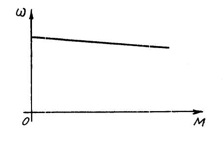
Fig. 10.2 Natural mechanical characteristic of parallel direct current motor
This means that when the electromagnetic moment of the engine is changed within a wide range, its speed is fairly stable (i.e., varies insignificantly).
Such engines are used where, when the load of the mechanism varies within wide limits, the speed of the engine should not change sharply? in electric drives of pumps, fans, etc.
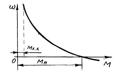
Fig. 10.3 Natural mechanical characteristica direct current DC motor
Natural mechanical characteristic of a DC motor of series excitation (Fig. 10.3) ?? soft , because its rigidity
β = Δ / Δω\u003e 10%.
This means that when the electromagnetic moment of the engine changes, even within a small range, its speed changes significantly.
Let us recall two characteristic features of this engine a direct current DC motor:
- With a reduction in the mechanical load on the shaft or its absence (=)
the speed of the engine increases sharply, the engine "goes peddling". Therefore, this engine can not be left unloaded on the shaft;
- At start-up the engine develops starting moments more than other types of motors.
These engines are not used on ships, but they are applied ashore, for example, in electric transport, in particular, in trolleybuses, where they do not remain unloaded on the shaft and where large starting moments are required (when the trolley starts moving).
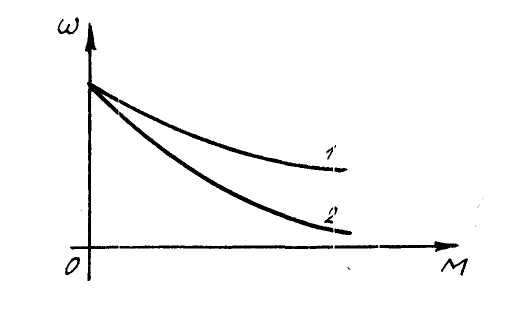
Fig. 10.4 Natural mechanical characteristics of DC motors of mixed excitation: 1 s parallel-sequential excitation;
2-s sequentially parallel excitation
Natural the mechanical characteristic of the mixed-excitation DC motor is intermediate between the characteristics of the parallel and sequential motors, the magnetic excitation flux is created by the joint action of both windings ?? parallel and serial.
There are two types of mixed excitation engines:
- with parallel ?? sequential excitation, in which the main part of the resulting magnetic flux is created by a parallel winding (up to 70%, the remaining 30% sequential);
2. with sequentially parallel excitation, in which the main part of the resulting magnetic flux is generated by a series winding (up to 70%, the remaining 30%parallel.
Therefore, the graph of the mechanical characteristics of the engine of the first type is more rigid than that of the second-type engine.
Both mechanical characteristics?? soft , because their rigidity
β = Δ / Δω\u003e 10%.
On ships, mixed excitation engines are used in regulated electric drives? winches, taps, windlasses and spiers.
The natural mechanical characteristic of an induction motor
Natural the mechanical characteristic of an induction motor has two sections ?? non-working (booster) AB and working aircraftD (Figure 8.8).
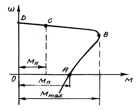
Fig. 10.5 Natural mechanical characteristic of an induction motor
At start-up the engine develops the starting torque(segment OA), after which it accelerates along the path ABC to the point C. At the same time in the section AB both the speed and the moment increase, at point B the motor develops the maximum moment. On the aircraft section, the speed continues to increase, and the moment decreases, to the nominal (point C). Location onBC the motor is overloaded, t. anywhere in this section the motor's electromagnetic torque is greater than the rated torque (> >).
Under normal conditions, the engine runs in section CD , the rigidity of which
β = Δ / Δω < 10%.
This means that when the torque varies over a wide range, the engine speed changes insignificantly.
Asynchronous motors have found the widest application on ships with an AC power plant.
The industry manufactures asynchronous motors of various series, for example, 4А ... ОМ2 (the fourth series of asynchronous motors), MAP (marine asynchronous pole-switching), МТF (with phase rotor), etc., specially for ships.
Thus engines of a series 4А ?? single-speed, MAP series ?? two- and three-speed, MTF series ?? the number of speeds is determined by the control scheme (up to 5 speeds).
Lecture 7.
2.5. Mechanical characteristics of a DC motor with series excitation. Motor mode
The scheme for switching on the engine is shown in Fig. 2.8. The motor armature M and the LM excitation winding are connected in series and are supplied from a single U source. Therefore, the armature current I i is also the excitation current I at . This circumstance determines the only difference in the design of a motor with successive excitation from an engine with independent excitation: the LM excitation coil of the DCT with successive excitation is made by a conductor of the same cross-section as the armature winding.
Fig. 2.8. Diagram of inclusion of DCT with consecutive excitation.
With a rotating armature in its winding, an emf is induced. rotation ^ E. On the scheme of switching on the engine direction E counter to the direction U, which corresponds to the motor operating mode. Value E is equal to:
Where ?
- angular velocity of the engine; F - engine flow;  - Constructive coefficient of the motor data for calculation, which are given in the reference books. Here r - number of pairs of motor poles; N - number of active armature winding conductors; a - the number of pairs of parallel branches of the armature winding.
Direction of anchor current I I , like the direction E on the connection diagram is shown for the motor operating mode.
Permissible value of the motor anchor current I i add is limited by the switching conditions and the mechanical strength of the armature and must not exceed the rated current I yang more than 2.5 times I i add ? 2.5 I yang .
In accordance with the equation of stress equilibrium under steady-state operation of the engine, the voltage U applied to the motor's anchor circuit is balanced by a drop in the voltage in the anchor chain I i R egg and induced in the armature winding emf. rotation E:
U = I Я R ЯЦ + Е
Where R JC = R I + R DP + R KO + R AT + R P - the total resistance of the anchor chain. Here R I - armature winding resistance; R DP - resistance of winding of additional poles; R KO - resistance of the compensation winding; R AT - resistance of the excitation winding; R P - resistance of the starting rheostat.
Value I I in the steady state will be:
In start mode ^ E = 0, therefore, because of the small resistance of the windings, the starting current I I'm may exceed the allowable value. To limit the starting current, a starting rheostat is used whose resistance R P is selected in such a way that I I'm ? I I'm an DOP
From the equation of stress equilibrium for the anchor chain, an analytical expression can be obtained for the mechanical characteristic of the engine.
Substituting it in place of emf. rotation ^ E its value and solving the resulting equation with respect to velocity, we obtain the dependence of the engine speed ? from armature current I I ? = f (I I ) , which is called the electromechanical characteristic:
Since the excitation winding is connected in series with the motor armature, the magnetic flux generated by it ^ Φ is an armature current function I I . Addiction Ф = f (I I ) is called the magnetization curve and has a nonlinear character of the "saturation zone" type. There is no precise analytical description of this curve, so there is also no exact analytical description of the mechanical characteristics of DPT with consecutive excitation. If, neglecting the saturation of the magnetic system, we assume a linear relationship between F and I I with a coefficient of proportionality ?, that is, Ф =? I I , then the torque is:
M = kΦI H = k? I H 2
Hence the value of the armature current will be:
Substituting in the equation of the electromechanical characteristic the value for I i , we obtain the equation of mechanical characteristic:
Where A = U / k ?; B = R JC / (k?) - constant values.
An analysis of the equation obtained shows that the ordinate axis is an asymptote for the curve and that in the region of small values of the moments it has a large steepness
When R P =0 and U = U mr. the engine operates on a natural characteristic. To build a natural characteristic, the so-called universal characteristics, which are given in the catalogs for each engine series, are used. They represent dependencies n = f (I I ) and M = f (I I ) in relative units. Knowing the nominal data of the engine, it is possible to construct its characteristic in absolute values. This characteristic is shown in Fig. 2.9.
Fig. 2.9. Mechanical characteristics of the DC motor of series excitation.
A feature of the characteristic is a sharp increase in speed with a decrease in the moment of resistance M from . Therefore, a DC motor with series excitation can not be started in those cases where M from mr. , since the motor speed can exceed the permissible value ?
additional =2,5 ?
mr. . This feature can be explained by considering the processes occurring in the engine with a decrease in the load. Let's assume that the engine worked at point A on the natural characteristic (see Figure 2.9.) In steady state at a speed ?
1
. When the moment of resistance decreases from the value M c1 for example, up to M c2 , a positive dynamic moment appears M D >0
and the engine speed starts to increase. With independent excitation, the consequence of this is an increase in the emf. rotation  and a decrease in armature current
  and torque
  . Increasing the speed and reducing the motor torque will continue until the motor torque M on will become equal M c2 and M D becomes zero.
With successive excitation of the emf. rotation E turns out to be a function of two quantities - increasing speed ? and decreasing flow F. As a result, the quantity E, and hence the quantities I I and M, with an increase in the speed will not significantly change, which leads to the conservation of M D >0 and further increase in speed. If the resistance of the starting rheostat R P >0 , then the static speed drop ?? from at the same moment of the engine will be more than on the natural characteristic. Therefore, the rheostat characteristics will have a large inclination to the abscissa axis.
With successive excitation, the torque is proportional to the square of the armature current  and limiting the starting current to the value I I'm an DOP ? 2.5I YaN allows us to obtain much more than with an independent excitation M DOP = 5 M H . DC motor overcurrent factor with series excitation by torque
K P = M DOP / M H is equal to five. This overload capacity is not possessed by more than one electric motor. It is thanks to this property that motors with sequential excitation are used in electric transport and lifting mechanisms.
Lecture 8.
^ 2.6. Mechanical characteristics of a DC motor with series excitation. Mode of electrical braking.
There are two modes of electric braking: dynamic braking and braking by opposing. Regenerative inhibition is not possible, since the emf. rotation Ethere can not be more than an anchor source voltage U.
^ Dynamic braking is realized in two ways: with self-excitation and with independent excitation. The scheme for switching on the engine and the mechanical characteristics for the first case are shown in Fig. 2.10.
Fig. 2.10. a) the scheme of switching on the engine in the mode of dynamic braking with self-excitation;
B) the characteristics of the engine in the mode of dynamic braking with self-excitation.
The motor is disconnected from the source voltage, and the field winding is switched in such a way that the direction of the current I AT in it was the same as in the motor mode (see Figure 2.8). This retention of the current direction eliminates the destruction of a small residual flux associated with the magnetization of the stator of the motor. This flow is the cause of self-excitation: in the winding of the armature, rotating under the action of inertial forces in the former direction, an emf is induced. E, the direction of which is the same as in the motor mode. Under the influence E A current appears in the dynamic braking circuit, which leads to an increase in the flux of Ф, the emf. E and current I I . Since the current I I in relation to the motor regime has the opposite direction, the motor torque becomes inhibitory. The motor from point A in the first quadrant passes to point B or C on the characteristic of dynamic braking in the second quadrant. Initially, the process of self-excitation passes very intensively and this leads to a braking torque throw, which can cause impacts in the mechanical part of the drive. Therefore, dynamic braking with independent excitation is more often used. The scheme for switching on the engine and the mechanical characteristics are shown in Fig. 2.11.
Fig. 2.11. a) the scheme for switching on the engine in the dynamic
Braking with independent excitation;
B) the characteristics of the engine in the dynamic
Braking with independent excitation.
The motor armature clamps are shorted to the dynamic braking resistance R DT , and the field winding is connected to the voltage of the source through the resistance R AT . The current in it is directed as in the motor mode and is set equal to the nominal. The characteristics are similar to those of DCT with independent excitation: they are linear, located in the second quadrant, and pass through the origin.
^ Deceleration stop , as for DCT with independent excitation, is carried out when the motor windings are switched on for one direction of rotation, and the motor armature rotates in the opposite direction against the inclusion under the influence of inertia forces or the active moment of resistance.
A reversible scheme for switching on the DCT with successive excitation is shown in Fig. 2.12.
![]()
Fig. 2.12. Reversible scheme of switching on DCT with series excitation.
The purpose of the elements is the same as in the circuit in Fig. 2.5. When the motor is reversed from the armature side, the current direction in the excitation winding LM is retained. Therefore, all processes during braking are analogous to those occurring in the circuit in Fig. 2.5. The characteristics of the engine are shown in Fig. 2.13.
Fig. 2.13.a) characteristics of DCT with consecutive excitation in the deceleration mode by anticoincidence.
B) similar characteristics with active M s.
Lecture 9.
^ 2.7. Mechanical characteristics of induction motors. Motor mode.
Asynchronous motors (AD) - the most common type of engines, because they are more simple and reliable in operation, with equal power have a smaller mass, dimensions and cost in comparison with DPT. Schemes for the inclusion of blood pressure are shown in Fig. 2.14.
Until recently, AD with squirrel-cage rotor were used in unregulated electric drives. However, with the advent of thyristor frequency converters (TPR) of the voltage supplying the stator windings of AD, squirrel-cage motors were used in adjustable electric drives. At present, power transistors and programmable controllers are used in frequency converters. The method of speed regulation is called impulse and its improvement is the most important direction in the development of the electric drive.
Fig. 2.14. a) the scheme of turning on the AD with a squirrel-cage rotor;
B) the scheme for switching on the AD with a phase rotor.
The equation for the mechanical characteristic of blood pressure can be obtained on the basis of the blood pressure substitution scheme. If we neglect the active resistance of the stator in this circuit, the expression for the mechanical characteristic will look like:
 ,
,
Where  ;
;  .
.
Here M to – critical moment; S to - the corresponding critical glide; U f - effective value of the phase voltage of the network; ? 0 = 2? F / p - angular velocity of the rotating magnetic field AD (synchronous speed); f Frequency of supply voltage; p - number of pairs of poles of blood pressure; x to - inductive phase short-circuit resistance (determined from the substitution circuit); S = (? 0 -?)/? 0 - sliding (rotor speed relative to the speed of the rotating field); R 2 1 - total active resistance of the rotor phase.
The mechanical characteristic of an AD with a squirrel-cage rotor is shown in Fig. 2.15.
Fig. 2.15. Mechanical characteristic of a short-circuited rotor.
There are three characteristic points on it. The coordinates of the first point ( S = 0; ? =? 0 ; M = 0). It corresponds to the ideal idling mode, when the speed of the rotor is equal to the speed of the rotating magnetic field. The coordinates of the second point ( S = S to ; M = M to). The engine works with the maximum torque. When M from \u003e M to the motor rotor will be forced to stop, which for the motor is a short-circuit mode. Therefore, the torque of the motor at this point is called critical M to . The coordinates of the third point ( S = 1; ? = 0; M = M p). At this point, the engine operates in the starting mode: rotor speed? = 0 and the starting torque acts on the fixed rotor M p . The section of the mechanical characteristic located between the first and second characteristic points is called the working section. On it, the engine runs in steady state. With a short-circuited rotor, if the conditions U = U mr. and f = f mr. a mechanical characteristic is called natural. In this case, in the working section of the characteristic there is a point corresponding to the nominal operating mode of the engine and having coordinates ( S mr. ; ? mr. ; M mr.).
Electromechanical characteristics of blood pressure ? = f (I f ) , which is depicted in Fig.2.15 as a dashed line, in contrast to the electromechanical characteristics of the DCT, coincides with the mechanical characteristic only at its working section. This is due to the fact that during start-up due to the changing frequency of the emf. in the rotor winding E 2 the frequency of the current and the ratio of the inductive and active resistances of the winding vary: at the start of the start the frequency of the current is large and the inductive resistance is greater than the active one; with increasing rotor speed ? the frequency of the rotor current, and hence the inductive resistance of its winding, decreases. Therefore, the inrush current of the AD in the direct start mode is 5-7 times higher than the nominal value I fn , and the starting torque M p is equal to the nominal M mr. . In contrast to DPT, where at start-up it is necessary to limit the starting current and the starting torque, when starting the AD, the starting current must be limited and the starting torque increased. The latter circumstance is most important, since the DCT with independent excitation is triggered when M from mr. , DFT with sequential excitation at M from mr. , and blood pressure during operation on a natural characteristic at M from mr. .
In AD with a squirrel-cage rotor, an increase M p A special design of the rotor winding is provided. The groove for the rotor winding is made deep, and the winding itself is arranged in two layers. When the motor is started, the frequency E 2 and the rotor currents are large, which leads to the appearance of the effect of current displacement - current flows only in the upper layer of the winding. Therefore, the winding resistance and starting torque of the motor M P . Its magnitude can reach 1.5M mr. .
In AD with a phased rotor, an increase M P is provided by changing its mechanical characteristics. If the resistance R P , included in the current flow path of the rotor, is zero - the motor operates on a natural characteristic and M P = M H . When R P >0 the total active resistance of the rotor phase is increased R 2 1 . Critical gliding S to as R 2 1 also increases. As a consequence, in AD with a phase rotor, the introduction R P in the current flow path of the rotor leads to a displacement M TO in the direction of large slides. When S TO = 1 M P = M TO . Mechanical characteristics of AD with a phase rotor at R P >0 are called artificial or rheostatic. They are shown in Fig. 2.16.
Fig. 2.16. Mechanical characteristics of AD with a phase rotor.
An induction motor with a squirrel-cage rotor will start at M p \u003e M from and will work at point A (see Figure 2.15). After this, the moment of resistance M from can be increased to M TO . AD, as well as DC motors, with increasing M from will automatically, without outside interference, reduce the speed ? and increase the torque M until M and M from Do not equal in size, i.e. from the steady-state regime with a higher speed to move to steady mode with a lower speed. When decreasing M from the opposite will be observed - the engine from the steady state at a lower speed will automatically switch to steady mode at a higher speed. The working section of the mechanical characteristic of a blood pressure is analogous to the mechanical characteristic of a DCT with independent excitation - a straight line inclined to the abscissa axis.
Such properties of blood pressure are due to the emf. E 2 , which is induced by the rotating magnetic field of the stator in the winding of the rotor. When M from \u003e M dynamic moment M d and rotor speed ? decreases. The magnetic field of the stator rotating at a constant speed ? 0 (synchronous speed) will cross the winding of the rotor with a high frequency. Therefore, the E 2 , the current in the rotor winding, the Ampere's force acting on its turns, and hence the torque M.
The overload ability of the AD for the moment is determined by the ratio of the critical moment M TO by the time of the nominal M H . For conventional ADs with a squirrel-cage rotor M TO / M H =1,7 , with a phase rotor M TO / M H =1,8 . For special crane pressures with a squirrel-cage rotor of the MTK type and a phase rotor of the MTKF type, the ratio M TO / M H = 2.3 h3.4.