Antipyretics for children are prescribed by a pediatrician. But there are situations of emergency care for fever, when the child needs to give the medicine immediately. Then the parents take responsibility and apply antipyretic drugs. What is allowed to give to infants? How can you bring down the temperature in older children? Which medications are the safest?
Lamps daylight long and firmly entered our life, and now get the most popularity, as the electricity is constantly becoming more expensive and the use of ordinary incandescent lamps becomes quite expensive. And energy-saving compact lamps not everyone can afford, and modern chandeliers require a large number of them, which calls into question the cost savings. That is why in modern apartments more and more fluorescent lamps are installed.
The device of fluorescent lamps
To understand how the fluorescent lamp works, it is necessary to study its device a little. The lamp consists of a thin glass cylindrical bulb, which can have a different diameter and shape.
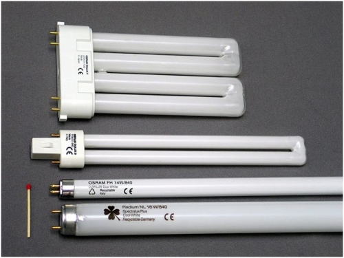
Lamps can be:
- direct;
- circular;
- U-shaped;
- compact (with E14 and E27 base).
Although they all differ in appearance, they all have one thing: they all have inside electrodes, a luminescent coating and a pumped inert gas, in which there are mercury vapor. The electrodes are small spirals that are heated for a short period of time and ignite the gas, due to which the phosphor applied to the lamp walls starts to glow. Since the ignition spirals have a small size, the standard voltage available in the home electrical network is not suitable for them. For this purpose, special devices are used - throttles, which limit the current to a nominal value, thanks to the inductive resistance. Also, to make the helix warm up briefly and not burned out, use one more element - the starter, which, after igniting the gas in the tubes of the lamp, disconnects the glow of the electrodes.

Throttle

Starter
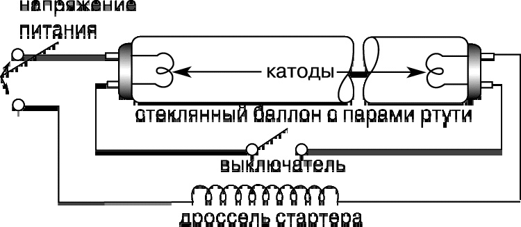
Principle of operation of a fluorescent lamp
The terminals of the assembled circuit are supplied with a voltage of 220V, which passes through the throttle to the first lamp spiral, then passes to a starter that is triggered and passes current to the second coil connected to the mains terminal. This can be clearly seen in the diagram below:

Often, a capacitor is installed at the input terminals, playing the role of a mains filter. It is his work part of the reactive power produced by the throttle, extinguished, and the lamp consumes less electricity.
How to connect a fluorescent lamp?
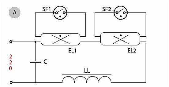
The connection scheme for fluorescent lamps, mentioned above, is the simplest one and is intended for ignition of one lamp. In order to connect two fluorescent lights, you need to slightly change the circuit, acting on the same principle of connecting all the elements sequentially, as shown below:

In this case, two starters are used, one for each lamp. When connecting two lamps to one choke, you should take into account its nominal power, which is indicated on its housing. For example, if it has a power of 40 W, then you can connect to it two identical lamps that have a load of not more than 20 watts.
There is also a scheme for connecting a fluorescent lamp without using starters. Thanks to the use of electronic ballast devices, ignition of lamps takes place instantly, without a characteristic "blinking" with starter control circuits.

Electronic Ballasts
To connect the lamp to such devices is very simple: detailed information is plotted on their case and it is schematically shown which lamp contacts need to be connected to the corresponding terminals. But that it was absolutely clear how to connect the lamp of daylight to electronic ballast, you need to look at a simple scheme:

The advantage of this connection is the lack of additional elements necessary for starter control circuits for lamps. In addition, with the simplification of the scheme, the reliability of the luminaire increases, since additional wire connections with starter motors are excluded, which are also rather unreliable devices.

Below is a diagram of the connection to the electronic ballast of two fluorescent lamps.
As a rule, complete with the electronic ballast device already have all the necessary wires for the assembly of the circuit, so there is no need to invent something and bear additional costs to purchase the missing items.
How to check the fluorescent lamp?
If the lamp does not light up, the probable cause of its malfunction may be a tungsten filament breaking, which heats the gas, causing the phosphor to glow. During operation, tungsten gradually evaporates, settling on the walls of the lamp. At the same time, a dark coating appears on the edges of the glass bulb, warning that soon the lamp can fail.
How to check the integrity of the tungsten filament? Very simply, you need to take a conventional tester, which can measure the resistance of the conductor and touch the lead-out ends of the lamp with probes.

The device shows a resistance of 9.9 Ohms, which eloquently tells us that the thread is intact.

Checking the second pair of electrodes, the tester shows a full zero, this side has a broken wire and therefore the lamp does not want to light.
The breakage of the spiral is due to the fact that in time the thread becomes thinner and the voltage passing through it gradually increases. Due to increased voltage, the starter goes out of order - this is evident from the characteristic "blinking" of the lamps. After replacing the burned lamps and starters, the circuit should work without adjustment.
If the inclusion of fluorescent lamps accompanied by extraneous sounds or the smell of burning is heard, you should immediately turn off the lamp and check the operability of all its elements. There is a possibility that the terminal connections are weak and the connection of the wires is heated. In addition, the throttle, if manufactured poorly, can have a winding closure of the windings and, as a consequence, the failure of fluorescent lamps.
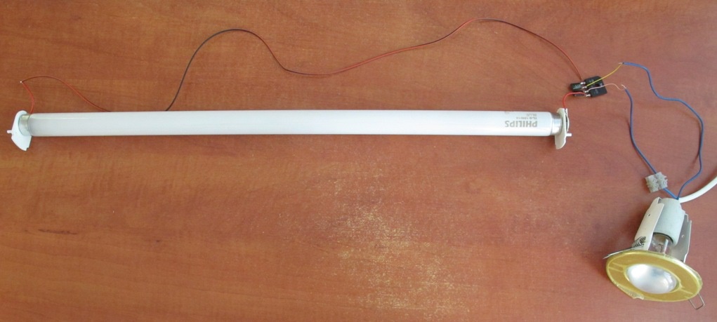
Fluorescent light bulb today can be found in almost any room. It is a source of daylight and provides an opportunity to save electricity. Therefore, such lamps are also called housekeepers.
Appearance of fluorescent lamp
But such products have one significant drawback - they burn out. And the reason for this is the combustion of the electronic filling - throttle or starter. This article will tell you about whether there is a way to connect fluorescent lamps without using a choke in an electrical circuit.
How the housekeeper works
The external appearance of fluorescent lamps may be different. Despite this, they have the same operating principle, which is realized due to the following elements, which usually contains the device circuit:
- electrodes;
- phosphor - special luminescent coating;
- a glass flask with an inert gas and mercury vapor inside.
The structure of the fluorescent light bulb
Such a fluorescent lamp is a gas discharge device with a sealed glass bulb. The gas mixture inside the bulb is selected in such a way as to reduce the energy costs necessary to support the ionization process.
Note! For such lamps to maintain a glow, you need to create a glow discharge.
For this purpose, a specific voltage is applied to the electrodes of the fluorescent lamp. They are located on opposite sides of the glass bulb. Each electrode has two contacts that connect to a current source. Thus, space is heated near the electrodes.
The actual connection scheme of this light source consists of a series of sequential actions:
- heating of electrodes;
- further on they supply a high-voltage pulse;
- the optimal voltage for creating a glow discharge is maintained in the electrical circuit.
As a result, an ultraviolet invisible glow is formed in the flask, which, passing through the phosphor, becomes visible to the human eye.
To maintain the voltage to create a glow discharge, the scheme of operation of fluorescent lamps involves the connection of the following devices:
- throttle. It acts as a ballast and is designed to limit the current flowing through the device to the optimum level;

Throttle for fluorescent light bulbs
- starter. It is designed to protect the fluorescent lamp from overheating. In doing so, it regulates the glow of the electrodes.
Very often the cause of breakage of the economy is the failure of the electronic filling of the ballast or burnout of the starter. To avoid this, you do not need to use flammable parts in the connection.

Standard Connection Scheme
The standard circuit used to connect fluorescent lamps can be modified (go without a throttle). This will minimize the risk of failure lighting device.

Inclusion option without ballast
As we found out, ballast in the device of a lamp of daylight plays an important role. At the same time, today there is a scheme in which you can avoid the inclusion of this element, which very often fails. You can avoid the inclusion of both ballast and starter.
Pay attention! This method of connection can also be used for burnt daylight tubes.
As you can see, this scheme does not contain a filament. In this case, the lamp / tube supply here will be provided through a diode bridge, which will create an increased constant pressure. But in such a situation it is necessary to remember that with this type of power supply the lighting product can darken on one side.
In the implementation, the above scheme is quite simple. It can be implemented with the help of old components. For this type of connection, you can use the following elements:
- 18 W tube / light source;
- assembly GBU 408. It will act as a diode bridge;

Diode bridge
- capacitors with an operating voltage not exceeding 1000 V, having a capacitance of 2 and 3 nF.
Note! When using more powerful light sources, it is necessary to increase the capacitors used in the circuit.
The assembled circuit
It should be remembered that the selection of diodes for the diode bridge, as well as the capacitors, must be done with a voltage margin.
A lighting device assembled in this way will give a luminosity slightly less in brightness than with a standard connection using a throttle and a starter.
What allows to achieve a non-standard version of the connection
The change in the usual way of connecting the components of the mains in fluorescent lighting is carried out in order to minimize the risk of damage to the device. The fluorescent lamps, despite the presence of impressive advantages, such as excellent luminous flux and low power consumption, have some drawbacks. They include:
- during their work they produce a certain noise (buzz), which is caused by the functioning of the ballast element;
- high risk of starter burnout;
- possibility of overheating of the filament.
The above scheme of connecting the components of the electric circuit will avoid all these disadvantages. When you use it, you will receive:
- a light bulb that will light instantly;

What the assembly looks like
- the device will operate silently;
- there is no starter, which often burns out with frequent use lighting system;
- it becomes possible to use a lamp with a burnt filament.
Here the role of the throttle will be performed by a conventional incandescent bulb. Therefore, in such a situation, there is no need to use expensive and bulky ballast.
Another connection option
There is also a slightly different suitable scheme:

Another connection option
It also uses a standard light source with a power roughly equal to a fluorescent lamp. In this case, the device itself must be connected to the power supply via a rectifier. It is collected according to the classical scheme used to double the voltage: VD1, VD2, C1 and C2.
This connection is made as follows:
- at the moment of inclusion inside the glass bulb there is no discharge;
- then double voltage of the network falls on it. Due to this, light is ignited;
- activation of the device occurs without preheating cathodes;
- after starting the electrical circuit, a current-limiting lamp (HL1) is turned on;
- at the same time, HL2, the working voltage and current are set. As a result, the incandescent lamp will glow faintly.
To ensure that the start-up is reliable, you need to connect the phase output of the network to the current-limiting lamp HL1.
In addition to this method, other variations of the standard switching scheme can be used.
Conclusion
Using modifications of the usual method of connecting fluorescent lamps, it is possible to exclude from the electric circuit such an element as a choke. In this case, it is possible to minimize the negative effect (for example, noise) that are observed when a standard lighting installation of this type is operated.
Daylight lamps (LDS) are widely used for lighting both large areas of public premises and as household light sources. The popularity of fluorescent lamps is due in large part to their economic characteristics. In comparison with incandescent lamps, this type of lamps has high efficiency, increased light output and a longer service life. However, a functional disadvantage of fluorescent lamps is the need for a starting starter or a special ballast (ballast). Accordingly, the task of starting a lamp when a starter fails or if it is missing is vital and relevant.
The principal difference between LDS and incandescent lamp is that the conversion of electricity into light occurs due to the current flowing through mercury vapors mixed with an inert gas in a flask. The current begins to flow after a gas breakdown with a high voltage applied to the electrodes of the lamp.
- Throttle.
- Bulb of a lamp.
- Luminescent layer.
- Contacts starter.
- Starter electrodes.
- Starter housing.
- Bimetallic plate.
- The filament of the lamp.
- Ultraviolet radiation.
- Discharge current.
The resulting ultraviolet radiation lies in the part of the spectrum invisible to the human eye. To convert it into a visible light flux, the walls of the bulb are covered with a special layer, a phosphor. By changing the composition of this layer, different light shades can be obtained.
Before the direct start of the LDS, the electrodes at its ends are heated by the passage of current through them or by the energy of a glow discharge.
A high breakdown voltage provides a ballast which can be assembled according to a known conventional circuit or have a more complex design.
The principle of the starter
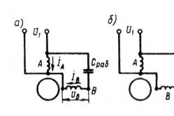
In Fig. 1 shows a typical connection of an LDS with a starter S and a throttle L. K1, K2 - lamp electrodes; C1 - cosine capacitor, C2 - filtering capacitor. A mandatory element of such circuits is a choke (inductor) and a starter (chopper). As the latter, a neon lamp with bimetallic plates is often used. To improve the low power factor due to the presence of the inductance of the throttle, use the input capacitor (C1 in Fig. 1).

Fig. 1 Functional diagram of LDS connection
The phases of the LDS launch are as follows:
1) Heating the lamp electrodes. In this phase, the current flows through the chain "Network - L - K1 - S - K2 - Network". In this mode, the starter starts chaotically closing / opening.
2) At the moment of breaking the circuit, the starter S energy magnetic fieldaccumulated in the throttle L, in the form of a high voltage is applied to the electrodes of the lamp. There is an electrical breakdown of the gas inside the lamp.
3) In breakdown mode, the resistance of the lamp is lower than the resistance of the starter branch. Therefore, the current flows along the contour "Network - L - K1 - K2 - Network". In this phase, the throttle L acts as a reactive current-limiting resistor.
Disadvantages of the traditional LDS start-up scheme: sound noise, flicker with a frequency of 100 Hz, increased starting time, low efficiency.
Principle of operation of electronic ballasts
Electronic ballasts (electronic ballast) use the potential of modern power electronics and are more complex, but also more functional circuits. These devices allow you to control the three phases of start-up and adjust the light flux. As a result, the lamp life is increased. Also, due to the power supply of the lamp with a current of a higher frequency (20 ÷ 100 kHz), there is no visible flicker. A simplified diagram of one of the popular topologies of electronic ballasts is shown in Fig. 2.

Fig. 2 Simplified circuit diagram of an electronic ballast
In Fig. 2 D1-D4 - mains voltage rectifier, C - filtering capacitor, T1-T4 - transistor bridge inverter with transformer Tr. Optionally, electronic ballasts may include an input filter, a power factor correction circuit, additional resonant chokes and capacitors.
A complete schematic diagram of one of the typical modern electronic ballasts is shown in Fig. 3.

Fig. 3 Electronic ballast scheme BIGLUZ
In the circuit (Figure 3), there are the main above mentioned elements: bridge diode rectifier, filtering capacitor in the DC link (C4), inverter in the form of two transistors with strapping (Q1, R5, R1) and (Q2, R2, R3), a throttle L1, a transformer with three terminals TR1, a start circuit and a resonant circuit of the lamp. Two windings of the transformer serve to turn on the transistors, the third winding is part of the resonant circuit of the LDS.
Ways to start LDS without specialized gear
If the fluorescent lamp fails, two reasons are possible:
1) . In this case, it is enough to replace the starter. The same operation should be carried out when the lamp flickers. In this case, when visually inspected, there are no characteristic blackouts on the LDS flask.
2). Probably, one of the threads of the electrodes has burnt out. At visual inspection, the darkening at the ends of the bulb may be noticeable. Here, it is possible to apply known start-up circuits to continue the operation of the lamp even with burnt-out electrode strands.
For an emergency start, the fluorescent lamp can be connected without a starter according to the scheme given below (Figure 4). Here the role of the starter is performed by the user. Contact S1 closes for the entire lamp operation period. The S2 button closes for 1-2 seconds to light the lamp. When S2 is opened, the voltage on it at the moment of ignition will be much larger than the network voltage! Therefore, when working with such a scheme, care should be taken.

Fig. 4 Schematic diagram start LDS without starter
If you want to quickly light the LDS with burned filaments, then you need to assemble the circuit (Figure 5).

Fig. 5 Schematic diagram of LDS connection with burned filament
For a 7-11 W throttle and a 20 W lamp, the C1 rating is 1 μF with a voltage of 630 V. Condensers with a lower rating should not be used.
Automatic circuits for starting LDS without a throttle assume the use of an ordinary incandescent lamp as a current limiter. Such circuits, as a rule, are multipliers and feed the LDS with a direct current, which causes the accelerated wear of one of the electrodes. However, we emphasize that such schemes allow some time to run even LDS with burned-out electrode wires. A typical scheme for connecting a fluorescent lamp without a choke is shown in Fig. 6.

Fig. 6. Structural diagram of LDS connection without throttle

Fig. 7 Voltage on the LDS connected according to the scheme (Fig. 6) until the moment of start-up
As you can see in Fig. 7, the voltage at the lamp at the time of start-up reaches the level of 700 V in about 25 ms. Instead of the incandescent lamp HL1, a choke can be used. The capacitors in the circuit in Fig. 6 should be selected in the range 1 ÷ 20 μF with a voltage of not less than 1000 V. Diodes should be designed for a reverse voltage of 1000V and a current of 0.5 to 10 A, depending on the power of the lamp. For a 40-watt lamp, there will be enough diodes with a current of 1.
Another variant of the startup scheme is shown in Fig. 8.

Fig. 8 Schematic diagram of a multiplier with two diodes
The parameters of the capacitors and diodes in the circuit in Fig. 8 are the same as in Fig. 6.
One of the options for using a low-voltage power supply is shown in Fig. 9. On the basis of this scheme (Figure 9), you can assemble a wireless fluorescent lamp on the battery.

Fig. 9 Schematic diagram of LDS connection from a low-voltage power supply
For the above scheme it is necessary to wind the transformer with three windings on one core (ring). As a rule, the first winding is first wound, then the main secondary (in the diagram it is designated as III). For the transistor, cooling must be provided.
Conclusion
If the starter of a fluorescent lamp fails, an emergency "manual" start or simple DC power circuits can be used. When using circuits based on voltage multipliers, it is possible to run the lamp without the throttle using an incandescent lamp. Working on direct current, there is no flicker and noise of LDS, but the service life is shortened.
If one or two filaments of the cathode of the fluorescent lamp burn out, it can be used for a while, using the above circuits with increased voltage.
Daylighting is an economical option, as a result of which it is an alternative to traditional lighting. The use of fluorescent lamps is concentrated in virtually all industries, and the use in domestic conditions is not ruled out. To date, such a light source is classified according to the brightness and shade of light emission: cold white, warm white and yellowish tone. However, for safety and normalization of work, it is customary to use a choke for fluorescent lamps.
Attention! Get fluorescent lamp only in specialized stores, ask for a guarantee on the device.
First of all, the throttle provides stable operation of fluorescent lamps. If you accidentally noticed the blackening at the ends of the lamp, pay attention, it is possible that the fault is in the stabilizer.
A throttle is a part that is equipped with an energy-saving lamp. The function of this device is to control the voltage at the output contacts of the light source. To light in fluorescent lamp did not extinguish, it is necessary to create a ballast, it can maintain the current in the contacts of the lamp at an optimum level. According to the production standards, the ballast is connected in series, then a starter is connected to it in parallel (it is responsible for igniting the lamp).
Throttle for fluorescent lamps
Important! The burnt out lamp is able to work without a throttle, only the correct algorithm of operation is needed.
Switching on the light in electrical network entails an input of high voltage, which is too much to work with, and the choke serves as an optimizer and only passes the required amount of current to illuminate the fluorescent lamps. But, sometimes, in order to reinsure, you need to know how to check the choke of a fluorescent lamp with a multimeter, and evaluate the quality, as well as the rate of work of the device. Also for this purpose you can use a light bulb with a cartridge and two loose wires. They are connected to the contacts of the device if they are ignited, therefore, the throttle is in working order.
How to connect a day lamp without a throttle?
A device providing a long-term work of a fluorescent lamp positively affects the internal mechanism, in addition, there is a separate connection diagram daylight without a throttle.
Such an experiment can be carried out even with burned-out elements and using various details.
- If the light bulb is burnt, we open it and remove the circuit from it. Please note that the bulb must remain intact and undamaged when removing the unit.
- We connect this circuit to a normal fluorescent lamp. That is, we connect the conductors to both sides of the lamp, then from the circuit we create a wire for the plug and plug it into the socket.
- If the luminescent source is working, then the experiment was a success.
As we see the experience is quite simple and working. In addition, there are even simpler solutions to this problem, for example, connecting the ballast to a common mechanism energy saving lamp.

Daylight lamp
Important! When connecting a fluorescent lamp without a choke, the filament is not used!
Certainly you will need a scheme for connecting a fluorescent lamp with a throttle. This option is suitable for an efficient and workable scheme of the mechanism. In fact, this option is available in two versions, but more accessible and easy to realize is the way in which all the contents of the fluorescent lamp are used, namely, the starter, throttle and capacitance, into which the standard voltage of the home network comes.
For beginners, it is not recommended to repair the throttle yourself, and sometimes it is impossible to do it, the ideal way is to make a complete replacement of the stabilizer. If you plan to switch without fluorescent lamps, it is important to follow a single scheme for all devices of this type.
Throttle Body Operating Mechanism
In appearance, the device is a cylinder in a metal casing. Its power necessarily coincides with the maximum permissible operating power of an energy-saving lamp. The throttle capability includes a feed restriction electric current, which prevents burnout of the bulb electrodes.
The throttle works in conjunction with the starter, individually they are not able to provide the necessary functions.

Wiring diagram of throttle
Consider how they work when you turn on daylight:
- the starter starts;
- electrodes are heated up and the electric current is supplied to the operating mechanism of the device;
- due to this, the bimetallic starter plate is heated;
- after warming up the contacts, the current comes to the throttle;
- the choke accumulates current, the gas penetrates, and the lamp begins to glow.
In the process of the economy lamp with an efficient starter and stabilizer, a uniform distribution of voltage occurs, if there is an arrival of overcurrents or current leakage.
Important! Connecting a fluorescent lamp without a throttle can not give a guarantee for the continued operation of the device.
Types of fluorescent lighting chokes
To date, electricians have recognized only two types of devices that work well with the mechanism of energy-saving fixtures.
- Electromagnetic choke-this type of instrument is switched in series with the fluorescent lamp. This option does not work from a cold start and requires the installation of a starter.
- Electronic throttle is an element that was invented not so long ago. The primary feature is simple circuit device. With such an installation, the lamp flickers and its pulsation decreases.
The lifetime of such devices is often dependent on the secured working conditions. It is worth noting that the temperature range should not vary by one degree from the values of + 5- + 55 ° C.
The electric scheme of connection of several fluorescent lamps with a throttle
Mercury arc lamp of high pressure, is one of the varieties of an electric lamp. It is widely used to illuminate large objects, for example, factories, factories, warehouses and even streets. It has a high light output, but it does not have a high degree of quality and light transmission is quite low.
Such devices have a very wide power spectrum, from fifty to two thousand watts, and operate from a standard 220 volt network at a frequency of fifty hertz.
The device and the principle of operation
The work is carried out thanks to a starting-regulating device consisting of an inductive choke.
Diagram of the device of the lamp
It consists of three main components:
- The base is the base and connects to the network.
- A quartz burner is the central mechanism of the device.
- Glass bulb - the main protective shell of glass.
The principle of operation of such a device is very simple, the voltage from the mains is suitable for the lamp. The current reaches the gap between one and the second pair of electrodes, which are placed at different ends of the lamp. Due to a small distance, the gases are easily ionized. After ionization in the gaps between the additional electrodes, the current flows to the main electrodes, after which the lamp begins to glow.

Different kinds
The maximum lamp flares up after about seven to ten minutes. This is due to the fact that mercury, which emits light during ignition, is a clot or a coating on the walls of the bulb and it needs time to warm up. The period of full inclusion is increased after some time during operation.
Classify drl llama in the form of cap, power, the principle of installation. Very often they are made with different materials, which can also be a classification of devices. There are varieties with the addition of special vapors into the structure, for example, such as sodium lamps, metal halide and xenon.
There is a variety with additional radiation of the red spectrum of light. They are called arc mercury-tungsten. Their appearance it does not differ from the standard device 250, but in their design they have a special incandescent spiral, which adds a red spectrum to the light flux.
Wiring diagram via throttle
In order for the lamp to work properly, the correct circuit for connecting this device is necessary. Thanks to a competent installation, lighting such a llama does not present any problems, and it will always work qualitatively and without failures.
In addition, improper connection increases the risk that the device will deteriorate and burn out early or at all, the first time it is turned on.
The connection scheme is quite simple and consists of a chain of a series-connected choke and the device itself. The connection is made to the 220-volt network and operates at a standard frequency. Therefore, they can easily be installed in a home network. The throttle works as a stabilizer and a work adjustor. Due to it the light source does not blink, it works continuously and at unstable incoming voltage the light flux remains unchanged.

Connecting the drill through a shake
Choke-free connection is not possible, as the lamp will immediately burn out. For start-up, the circuit must be powered by a rather high voltage, which sometimes reaches a level equivalent to two or three incoming voltages.
As previously stated, the device does not light up immediately. In rare cases, the full warm-up and start of work at full capacity can be after fifteen minutes.
We check working capacity
If after connecting your lamp does not want to work or does not work correctly, you should check it and conduct the test and make sure it is working. To do this, you can use a special tester or an ohmmeter.
With their help, it is necessary to check all winding turns for a break or short circuit between adjacent turns. If the circuit has a break, then the resistance will be infinitely large and the instrument will display an abnormal value. In this case, it is necessary to completely replace the winding.
If there is no rupture, but there is a loss of insulation due to which there is a short circuit, the resistance will rise slightly. If a small number of turns interact with each other, then the increase will be insignificant.
If the closure occurs in the winding of the throttle, then there will be practically no increase in resistance and this will not affect the operation of the device in any way. If you check the entire winding with an ohmmeter or a tester and you do not find any problems, you need to look for the problem in the light bulb itself or in the power supply system.
Run the lamp without the throttle
If you want to use the drl 250 model as usual without using a standard choke, it can be connected using a special technology.
The simplest connection option is the purchase of a special drill 250, which can operate without a choke. It is equipped with a special spiral, which works as a stabilizer and additionally dilutes the emitted light.
One option is not to use a choke, is the connection to the circuit a conventional lamp incandescent. It should have the same power as the drill to produce the necessary resistance and apply voltage to the source light 250.
Another option to remove the throttle from the design is to install a capacitor or a group of capacitors. But in this case, you need to accurately calculate the current they give out. It must fully correspond to the necessary voltage for operation.