Antipyretics for children are prescribed by a pediatrician. But there are situations of emergency care for fever, when the child needs to give the medicine immediately. Then the parents take responsibility and apply antipyretic drugs. What is allowed to give to infants? How can you bring down the temperature in older children? Which medications are the safest?
Hello friends. In the era of LED technology, many still prefer to use fluorescent lamps for lighting (they are also housekeepers). This is a type of gas-discharge lamps, which many consider, to put it mildly, not a very safe kind of lighting.
But, contrary to all doubts, they successfully hung in our homes for more than a decade, so many have retained non-working economy-lamps.
As we know, for the operation of many gas-discharge lamps requires high voltage, sometimes several times higher than the voltage in the network and the usual housekeeper is also no exception.
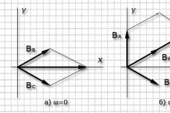
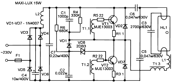
Pulsed converters, or ballasts, are built into such lamps. As a rule, in budgetary versions a half-bridge autogenerator converter is used according to a very popular scheme. The circuit of this power supply unit works quite reliably, despite the complete absence of any protection, in addition to the fuse. There is not even a normal master oscillator. The trigger chain is built on the basis of a symmetric diac.
The circuit is the same as that of y, but instead of the step-down transformer, a storage choke is used from there. I intend to quickly and clearly show you how you can turn such power supplies into a full pulse source power supply, reducing type, plus provide galvanic isolation from the network for safe operation.
First of all, I want to say that the converted unit can be used as a basis for chargers, power supplies for amplifiers. In general, you can implement where there is a need for a power source.
It is only necessary to refine the output with a diode rectifier and a smoothing capacitance.

Suitable for rework any housekeeper of any power. In my case, it's a fully working 125 Watt lamp. The lamp must first be opened, the power unit is removed, and the bulb is no longer needed. Do not even try to break it, because it contains very toxic fumes of mercury, which are deadly to living organisms.
First of all, we look at the ballast scheme.

They are all the same, but they can differ in the number of additional components. On the board immediately strikes a rather massive choke. We warm up the soldering iron and evaporate it.


On the board we also have a small ring.

This is a feedback transformer and it consists of three windings, two of which are master,

and the third is the feedback winding of the flow and contains only one revolution.

And now we need to connect the transformer from computer block power supply as shown in the diagram.
That is, one of the leads of the network winding is connected to the feedback winding.

The second terminal is connected to the connection point of two half-bridge capacitors.

Yes, friends, this is the end of the process. You see how simple it all is.
Now I'll load the output winding of the transformer to make sure the voltage is available.

Do not forget, the initial launch of the ballast is done by a safety light bulb. If the power supply is needed at low power, you can do without any transformer at all, and wind the secondary winding directly on the throttle itself.

It would not hurt to install power transistors on radiators. In the course of work under load, their heating is a natural phenomenon.

The secondary winding of the transformer can be made for any voltage.
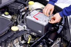
For this you need to rewind it, but if the block is needed, for example, for charger car battery, then you can do without rewinding. For a rectifier, it is worth using pulse diodes, again, the optimal solution is our KD213 with any letter.
In the end, I want to say that this is just one of the options for altering such blocks. Naturally, there are many other ways. On this, friends, everything. Well, with you, as always, was KASYAN AKA. Until next time. Till!
The boom of fluorescent energy-saving lamps is gradually coming to its end. They have already been replaced by LED lamps, which have undeniable advantages: better economy, instant access to operating conditions, longer service life, they do not contain mercury vapors and do not emit ultraviolet light after burning the phosphor inside the bulb. The only hitch is still the high cost of LED lamps. But if there is a failed fluorescent energy saving lamp, then it can easily be converted into an LED lamp, using the methods listed below.
First a small preface.
Acquired several years ago, energy saving lamps of ECOLIGHT company pretty quickly began to fail. First, the filament burned in the bulb of one lamp, but this malfunction was promptly eliminated by installing a jumper on the printed circuit board in parallel with a tattered filament. The lamp was also perfectly lit from the remaining whole filament. Then the same fate befell the second lamp. After the repair, after having worked for another six months, the remaining filaments were burned first in one lamp, and a month later in another. Contact with fluorescent lamps no longer wanted, and there was an idea about the reworking of failed lamps in LED.
The first lamp had a power of 18 watts and a fairly wide body with a diameter of 55 mm, which led to the idea of installing several dozen ultra-bright white LEDs with a working current of 20 mA, plugging them into the network in series through the diode bridge, and using a condenser as a quenching ballast. The result is the diagram shown in the figure below:
In all, 40 LEDs HL-654H245WC ø4.8 mm with a brightness of 1.5 Cd and an angle of 140 ° were used. The circuit is assembled on two printed circuit boards from one-sided foil-coated fiberglass:

Between each other, the boards are fastened together with one stand in the center. Here's what happened:

Subjectively, the luminescence of this lamp turned out to be about the same as that of a 30-watt incandescent lamp, and the power consumption was only 1.1 W:

The color of the lamp is much colder than the incandescent lamp.
Interestingly, the same and similar brightness LEDs of warm and cold colors available for sale differ in price by 4 times, but even the applied LEDs of warm glow (more expensive) have a bluish tinge in comparison with the incandescent lamp. With regard to the resulting value of the lED Bulb, then it turned out to be at the ready-made level with the same number of LEDs. It is not known whether there is a rectifier with a smoothing capacitor in these ready-made 220 V lamps. Most likely, no, because it is easier and cheaper to connect in series the pairs of LEDs on and on, and add a ballast capacitor. And let the lamp with a double frequency of the network blink to itself, after all to the Chinese manufacturer there is no point to the view of the consumer.
Considering the rather high cost of forty LEDs (0.125 $ * 40 = 5 $), for reworking a second 9W bulb in a 38.5 mm package

it was decided to use one powerful three-fold LED. The choice fell on EDEX-3LA1-E1 at a cost of $ 1,875, having the following characteristics:
color temperature ............................... 3200 K;
luminous flux (at a current of 700 mA) .............. 130 lm;
angle of illumination 135 °;
operating current ............................................. 700 mA;
voltage .............................................. 4 V.
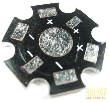
These LEDs are available for sale ready-made radiators "STAR" at a cost of $ 0.156:
To get a current of up to 700mA for powering such a powerful LED, it was decided to use an existing converter in a burnt out fluorescent lamp. By closing all the leads of the lamp bulb and winding the additional winding on the available choke on the board, such a converter can turn the power source with minimal cost. In fact, a ready-made electronic transformer is obtained from the lamp, it is only necessary to provide a stabilized current for powering the LED.
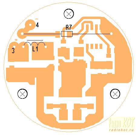
Here is the scheme energy saving lamp, copied directly from the board:

To convert it into an electronic transformer, you just need to remove the flask, close the points 2 and 4 of the board and wind the additional winding on the L2 choke. A rectifier with a filter is connected to the additional winding.
To stabilize the current through the LED, the method proposed in Ref. Its essence consists in winding an additional winding on the control transformer T1 and shunting it with opening field effect transistors To disrupt oscillations of the converter when the output voltage (current) is exceeded. However, nothing good came out of this. As shown by the analysis of the operation of the above circuit, it takes about 3 ms to restore the converter oscillations to charge the capacitor C3 to the breakdown voltage of the DB3 (30 V) diode. Even with very short-term shunting of the additional winding at T1, the restart time of the converter was about 3 ms. As a result, the regulating characteristic of the converter is incomplete. When trying to "slightly" reduce the output voltage, for example up to 90 ... 95%, at the output of the rectifier filter (with an additional power winding of the throttle) instead of constant voltage immediately appeared short positive pulses with relatively long dips of 3 ms. Those. the control limits were possible only at the initial small section of the converter operation.
Therefore, another circuit solution was used, shown in the figure below:

The additional circuit is an impulse current stabilizer assembled without the use of specialized microcircuits on a widely used low-cost element base. An additional winding is wound on the choke of the lamp, the voltage from which is fed to the diode bridge VD1 ... VD4 with filter capacitors C1, C3. The use of the bridge circuit is caused by the complexity of winding the L2 choke by half a large number of turns with a tap from the middle due to the limited space.
The DA1 chip is equipped with a voltage stabilizer +2.5 V to power the comparator DA2 and a resistive driver of the reference voltage R5, R6. Resistor R7 with a resistance of 0.1 ohms serves as a current sensor. The transistors VT1, VT2 have a power key. In the initial state, when the power is applied, while the current through LED HL1 is not flowing, at the output of comparator DA2 is high, VT1 is closed and VT2 is open through R4. Through the throttle L1, an increasing current flows into the load. If the reference voltage is exceeded on the inverting input of the comparator DA2, the latter switches to a low output state. VT1 opens abruptly and shunts junction VT2, closing the latter and causing a self-induction current in the circuit VD5, L1, C4, C5, HL1, R7. After reducing the voltage at the inverting input of the comparator DA2 as the discharge of C4, C5, the latter again goes into a state with a high level at the output. VT1 is closed, VT2 is opened and the whole process is repeated anew. The oscillation frequency with an input voltage of 7 V is 50 ... 70 kHz. The measured efficiency of a pulsed current stabilizer was 86%.
The current value through the LED is selected to be 0.6 A for a more gentle operation and less heating.
The procedure of converting an energy saving lamp
The lamp body is opened with a flat screwdriver (fastening on latches). The upper part with the bulb is carefully disposed of (Caution: In the flask of mercury vapor, if the bulb is damaged, it is necessary to treat the surrounding contacting objects with a solution of potassium permanganate). From the board, the capacitor C5 can be evaporated. in the work he does not participate. Points 2 and 4 on the board are shortened. The L2 choke is soldered and an additional winding of 14 turns is wound around the MGTF-0.1 wire (almost to the full filling of the gap). It is better to use MGTF for a good galvanic isolation.

The throttle is soldered into place. It will not hurt to check the ESR-meter electrolyte C3. If possible, it is better to replace it with a new capacity of 4.7 ... 10 μF x 400 V (105 ° C). This will reduce the ripple frequency of 100 Hz at the output of the converter.
After that, a board made of unilateral foil fiberglass is manufactured:

To produce the L1 throttle, we used the ready-made DP2-0.1 for 100 μH. With it, the knife is taken off the staff winding and wound with a new wire PEV2 ø0.3 mm in uniformly along the entire length of the core in 3 layers. The inductance of the choke is 51 μH. You can also use a commercially available choke with an inductance of 47 μH and rated for at least 1.5 ... 2 A.
The transistor VT2 IRLML6401 can be changed to IRLML6402.
Diodes VD1 ... VD4 SS14 can be replaced with any suitable Schottky SMD-diodes, designed for a current of at least 1A and a reverse voltage of 30 ... 40V, for example SM5818, SM5819.
The diode VD5 SS24 (2A, 40V) will be replaced with SS22, 10BQ015 or similar.
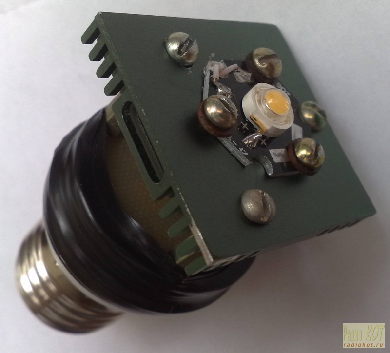
As it was said above, the LED decouples into a ready-made radiator "STAR", which in turn is installed on a more massive radiator. In this case a radiator was used from the old motherboard. With cut off "ears" fastening its dimensions 37.5 x 37.5 x 6 mm. The radiator is attached to an additional board on 3 racks M3x15. The board itself is attached to the top of the lamp body by several turns of electrical tape. Between the staff and additional boards it is necessary to lay an insulation gasket, cut, for example, from non-flinted fiberglass.


The first inclusion of the modified lamp is desirable to produce with a load in the form of a 5-watt resistor with a resistance of 5 ... 6 Ohm with a series-connected ammeter. It is safer to connect the lamp to the 220 V network through a regular incandescent bulb for 40 ... 60 W. In normal operation, its spiral should not glow. At the cathode of VD5 rectangular pulses of frequency 50 ... 70 kHz should be present. The voltage on C3 must be 5 ... 8 V, the current through the load is 0.6 A. More precisely, the current value can be set by selecting the resistance of the resistor R5. After that, you can connect the LED.
Subjectively, the brightness of the glow of the lamp thus modified corresponds to a 30 W incandescent lamp. The hue is warm, but in comparison with the incandescent lamp a little colder. The measured power consumption was 3.3 W:

The cost of the second version of the LED lamp was about 3.2 $.
Literature:
1) How to stabilize an electronic transformer. AE Shufotinsky. Radioamateur №1 / 2010.
ID: 1371
|
How do you like this article? |
In this article you will find a detailed description of the process of manufacturing of pulse power units of different power based on electronic ballast of a compact fluorescent lamp.
Pulse power supply for 5 ... 20 watts you can produce in less than an hour. The manufacture of a 100-watt power supply will take several hours. You can make and more powerful electronic transformers, for example on IR2153, but it is possible BUY READY and remake to their own tensions.
At present, Compact Fluorescent Lamps (CFL) are widely used. To reduce the size of the ballast throttle, they use a high-frequency voltage converter circuit, which allows to significantly reduce the throttle size.
In the event of an electronic ballast failure, it can easily be repaired. But, when the bulb itself breaks down, the bulb is usually thrown out.
However, the electronic ballast of such a light bulb is almost ready impulse Power Supply (PSU), and quite compact. The only thing that the electronic ballast circuit differs from the current switching power supply is the lack of a separation transformer and a rectifier, if necessary.
At the same time, modern radio amateurs are experiencing great difficulties in finding power transformers to power their homemade products. Even if a transformer is found, then rewinding requires the use of a large amount copper wire, and mass-dimensional parameters of products assembled on the basis of power transformers are not encouraging. But in the overwhelming majority of cases power transformer can be replaced by a pulsed power supply. If, for this purpose, ballast is used from faulty energy-saving lamps, the savings will be a considerable amount, especially if we are talking about transformers of 100 watts or more.
The difference between the ballast circuit of an energy-saving lamp from a pulsed power supply
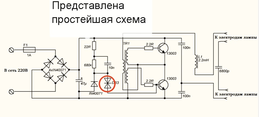
This is one of the most common electrical circuits of energy-saving lamps. To convert a CFL circuit to a switching power supply, it is sufficient to install only one bridge between the points A - A 'and add a pulse transformer with a rectifier. Red color indicates items that can be deleted.

Energy saving lamp scheme
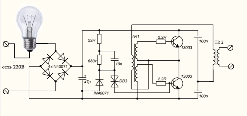
And this is a complete circuit of a pulsed power supply, assembled on the basis of ballast of a fluorescent lamp using an additional pulse transformer.
For simplicity, the fluorescent lamp and several parts that have been replaced by a jumper are removed.
As you can see, the CFL scheme does not require major changes. Red color indicates additional elements introduced into the scheme.

Completed circuit of a switching power supply
What power supply unit can be made from CFL?
Power pulsed power supply is limited by the overall power of the pulse transformer, maximally permissible current key transistors and the value of the cooling radiator, if used.
A small power unit can be built by winding the secondary winding directly onto the frame of the already existing throttle.

BP with secondary winding directly on the frame of the already existing throttle
In the event that the throttle window does not allow winding the secondary winding or if it is required to build a power supply unit with a power significantly higher than the CFL power, an additional pulse transformer will be needed.
BP with additional pulse transformer
If you want to get a power supply with a capacity of more than 100 watts, and you use ballast from a 20-30 Watt lamp, then most likely you will have to make small changes to the electronic ballast circuit.
In particular, it may be necessary to install more high-power diodes VD1-VD4 in the input bridge rectifier and rewind the input reactor L0 with a thicker wire. If the current transistor gain is not sufficient, you will have to increase the base current of the transistors by reducing the resistor values R5, R6. In addition, it will be necessary to increase the power of the resistors in the base and emitter circuits.
If the generation frequency is not very high, it may be necessary to increase the capacitance of the separation capacitors C4, C6.
Pulse transformer for power supply

A feature of half-bridge switching power supplies with self-excitation is the ability to adapt to the parameters of the transformer used. And the fact that the feedback loop will not pass through our self-made transformer and at all simplifies the task of calculating the transformer and setting up the unit. Power units, assembled under these schemes forgive errors in calculations up to 150% and higher. Tested in practice.
Do not be scared! You can wind a pulse transformer during a single movie or even faster if you are going to do this monotonous work in a concentrated manner.
Input filter and voltage surge capacity

In input filters of electronic ballasts, because of space saving, small capacitors are used, on which the value of voltage pulsations with a frequency of 100 Hz depends.
To reduce the level of voltage pulsations at the output of the power supply, it is necessary to increase the capacitance of the input filter capacitor. It is desirable that for each Watt the power of the PSU should be one microfarad or so. An increase in the capacitance C0 will cause an increase in the peak current flowing through the diodes of the rectifier at the instant of switching on the power unit. To limit this current, a resistor R0 is needed. But, the power of the original CLL resistor is small for such currents and it should be replaced by a more powerful one.
If you want to build a compact power supply, then you can use electrolytic capacitors, used in flash bulbs film "mallies." For example, in one-time Kodak cameras, miniature capacitors without identification marks are installed, but their capacity is as much as 100μF at a voltage of 350 volts.
Power supply unit 20 Watt

Power supply unit 20 Watt
A power supply unit with a power close to that of the original CFL can be assembled without even a separate transformer being wound. If the original throttle has enough free space in the magnetic circuit, you can wind up a couple of dozen turns of wire and get, for example, a power supply for a charger or a small power amplifier.

The picture shows that one layer was wound over the existing winding insulated wire. I used the MGTF wire ( stranded wire in fluoroplastic insulation). However, in this way it is possible to obtain a power of only a few watts, since most of the window will be occupied by the insulation of the wire, and the cross-section of the copper itself will be small.
If you need more power, you can use an ordinary copper lacquered winding wire.
Attention! The original winding of the throttle is energized! With the above modification, be sure to worry about reliable interwinding insulation, especially if the secondary winding is wound with a conventional lacquered winding wire. Even if the primary winding is covered with a synthetic protective film, an additional paper pad is necessary!

As you can see, the winding of the throttle is covered with a synthetic film, although often the winding of these chokes is not protected at all.

We wind two layers of electrocardboard with a thickness of 0.05 mm or one layer 0.1 mm thick on top of the film. If there is no electrocardboard, we use any paper that is suitable for thickness.

Over the insulating spacer, we wind the secondary winding of the future transformer. Wire cross-section should be chosen as much as possible. The number of turns is selected experimentally, there will be few of them.
Thus, I was able to obtain power at a load of 20 watts at a transformer temperature of 60 ° C and transistors at 42 ° C. To get even more power, at a reasonable temperature of the transformer, the too small area of the magnetic circuit window and the resulting wire cross section prevented it.

In the picture, the current BP model
The power supplied to the load is 20 watts.
The frequency of auto-oscillations without load is 26 kHz.
The frequency of self-oscillations at the maximum load is 32 kHz
Transformer temperature - 60? C
The temperature of the transistors is 42? C
To increase the power unit's power, we had to wind the pulse transformer TV2. In addition, I increased the capacity of the filter capacitor C0 to 100μF.

100 Watt power supply unit
Since the efficiency of the power supply does not equal 100%, I had to screw some radiators to the transistors.
After all, if the efficiency of the unit is even 90%, it will still have to dissipate 10 watts of power.
![]()
I was not lucky, in my electron ballast transistors 13003 pos.1 were installed, of such a design, which, apparently, is designed for fixing to the radiator with the help of shaped springs. These transistors do not need gaskets, since they are not equipped with a metal pad, but heat is much worse. I replaced them with transistors 13007 pos.2 with holes so that they can be screwed to the radiators with conventional screws. In addition, 13007 have several times the large permissible currents. You can buy separately MJE13007.
If you want, you can safely screw both transistors on one radiator. I checked it works.

Only, the case of both transistors should be isolated from the radiator housing, even if the radiator is inside the electronic device housing.
Fastening is conveniently done with screws M2.5, on which it is necessary to put insulating washers and pieces of insulating tube (cambric) beforehand. It is allowed to use heat conductive paste KPT-8, since it does not conduct current.
Attention! The transistors are under voltage of the network, therefore insulating gaskets must provide electrical safety conditions!

Operating 100W pulsed power supply unit
Resistors of the equivalent load are placed in water, since their power is insufficient.
The power released on the load is 100 watts.
The frequency of auto-oscillations at the maximum load is 90 kHz.
The frequency of auto-oscillations without load is 28.5 kHz.
The temperature of the transistors is 75? C.
The area of the radiators of each transistor is 27 cm ?.
The temperature of the throttle TV1 is 45? C.
TV2 - 2000HM (O28 x O16 x 9mm)
Rectifier
All secondary rectifiers of a half-bridge switching power supply must necessarily be full-wave. If this condition is not met, then the mag- netoprint can enter saturation.

There are two widespread circuits of full-wave rectifiers.
1. The bridge circuit.
2. The scheme with a zero point.
Bridge circuit allows you to save a meter of wire, but dissipates twice more energy on diodes.
A zero-point circuit is more economical, but requires two completely symmetrical secondary windings. Asymmetry by the number of turns or arrangement can lead to saturation of the magnetic circuit.
However, it is the zero-point circuits that are used when high currents are required at a low output voltage. Then, to minimize losses, instead of conventional silicon diodes, Schottky diodes are used, at which the voltage drop is two to three times less.
Example.
The rectifiers of the computer power units are made according to the scheme with a zero point. With a power output of 100 watts and a voltage of 5 volts, even 8 watts can dissipate on Schottky diodes.
100/5 * 0.4 = 8 (Watt)
If you use a bridge rectifier, and even conventional diodes, the power dissipated on diodes can reach 32 watts or even more.
100/5 * 0.8 * 2 = 32 (Watt).
Pay attention to this, when you will design the power supply to not then look for where half of the power has disappeared.

In low-voltage rectifiers, it is better to use a zero-point circuit. As with manual winding, you can simply wind the winding into two wires. In addition, powerful impulse diodes are not cheap.
How to properly connect a switching power supply to the network?

For the adjustment of switching power supplies, the following switching scheme is usually used. Here the incandescent lamp is used as a ballast with a non-linear characteristic and protects the UPS from failure in case of emergency situations. The lamp power is usually chosen close to the power of the pulsed PSU under test.
When the impulse BP is operating at idle or under low load, the resistance of the lamp's thread is small and does not affect the operation of the unit. When, for whatever reason, the current of the key transistors increases, the lamp's spiral becomes hotter and its resistance increases, which leads to current limitation to a safe value.

This figure shows a diagram of the stand for testing and setting up pulsed PSUs that meet electrical safety standards. The difference between this scheme and the previous one is that it is equipped with a separating transformer, which provides galvanic isolation of the UPS under examination from the lighting network. The switch SA2 allows to block the lamp when the power supply unit gives off a lot of power.
An important operation in testing a PSU is a load equivalent test. As a load it is convenient to use powerful resistors of the type PEV, PPB, PSB, etc. These "glass-ceramic" resistors are easy to find on the radio market by the green coloring. Red numbers - power dissipation.

It is known from experience that the power of the equivalent load for some reason is always not enough. The above resistors can dissipate power two or three times higher than the nominal one for a limited time. When the power supply is switched on for a long time to check the thermal conditions, and the equivalent load capacity is insufficient, the resistors can simply be lowered into the water.
Be careful, watch out for the burn!
Load resistors of this type can heat up to a temperature of several hundred degrees without any external manifestations!
That is, you will not notice any smoke or color changes and you can try to touch the resistor with your fingers.
How to set up a switching power supply?
Actually, the power unit, assembled on the basis of a functioning electronic ballast, does not require special adjustment.
It must be connected to the equivalent load and make sure that the PSU is able to give the calculated power.
During the run under maximum load, it is necessary to follow the dynamics of temperature growth of transistors and transformer. If the transformer is heated too much, then it is necessary, either to increase the cross-section of the wire, or to increase the overall power of the magnetic circuit, or both.
If the transistors are heated, then you need to install them on the radiators.
If the DC transformer is used as an impulse transformer from CFL, and its temperature exceeds 60 ... 65? C, then it is necessary to reduce the load power.
IMPULSE POWER SUPPLY FROM ENERGY-SAVING LAMP Low-power impulse power supply unit from improvised materials with own hands
What is the purpose of the circuit elements of the switching power supply?
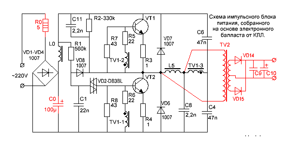
Diagram of a switching power supply
R0 - limits the peak current flowing through the diodes of the rectifier, at the moment of switching on. In CFL also often performs the function of a fuse.
VD1 ... VD4 - bridge rectifier.
L0, C0 is the power filter.
R1, C1, VD2, VD8 - the starting circuit of the converter.
The start node works as follows. Capacitor C1 is charged from the source through resistor R1. When the voltage across the capacitor C1 reaches the breakdown voltage of the transistor VD2, the diistor opens itself and unlocks the transistor VT2, causing self-oscillation. After occurrence of generation, rectangular pulses are applied to the cathode of the diode VD8 and the negative potential reliably locks the dynistor VD2.
R2, C11, C8 - make it easy to start the converter.
R7, R8 - improve the locking of transistors.
R5, R6 - limit the current of the bases of transistors.
R3, R4 - prevent saturation of transistors and act as fuses in the breakdown of transistors.
VD7, VD6 - protect the transistors from reverse voltage.
TV1 is a feedback transformer.
L5 - ballast throttle.
C4, C6 - separating capacitors, on which the supply voltage is divided in half.
TV2 - pulse transformer.
VD14, VD15 are pulse diodes.
C9, C10 - filter capacitors.
On the materials of the site http://www.ruqrz.com/
For greater clarity, several schematic diagrams of lamps of popular manufacturers are given:


Over time, in the glove box of any radio amateur, a huge amount of electronic stuffing from energy saving light bulbs, and many radio components of them can be actively used in other radio amateur tracks. So the high-voltage generator from the ballast of the usual energy-saving lamp is assembled for 5 minutes, and the power supply of the Tesla generator is already there.

As practice shows, daylight lamps work for years. But over time, their luminosity diminishes. Such lamps, of course, can still serve you until the flask filled with an inert gas breaks through a high-voltage discharge, but it is not advisable to bring them to this state, because the electronic part can also burn, but you can still use it.

Inside the energy-saving housing there is electronic circuit - ballast. This is a ready-to-raise high-voltage converter of the AC-DC type, it is necessary to increase the standard 220 volts to 1000 volts. Attention, at its output there is a life-threatening strain, so during the experiments observe extreme caution and always remember about.
To build a high-voltage generator circuit, we will need a line transformer, it can be borrowed from a horizontal scan unit, such people are massively discarded, so it is not at all a problem to find it. Another important component of the high-voltage design is a capacitor. By the way, it can also be found in a horizontal scan unit, for example 2200 pF 5 kV. The voltage from the ballast goes to the winding of the line transformer not directly, but through the capacitor, this connection protects the ballast circuit. On the correct extraction of the line transformer, I propose to learn from the video:
Using a multimeter on the transformer, we find the winding with the maximum resistance (except for the high-voltage) and apply voltage to it from the ballast. Such a high-voltage generator can be used in experiments with electricity. If you add two metal bars - we get the "ladder of Jacob". Even on it you can collect, because the circuit is able to feed a line transformer in a day, and the voltage at the output of a line transformer of 5 kV.
To operate the screwdriver you need a power supply unit at 18 V. These devices operate on a 220 V network. The main element of the units is the converter. To date, there are many modifications, which differ in parameters and constructive elements. How to make a power supply unit on a screwdriver 18B with your own hands? For this it is recommended to consider specific assembly schemes.
Models with indication
The power supply to the screwdriver 18V for operation from the network with indications can be made on the basis of a wired converter. The conductivity of the element must be 4.5 m. Capacitors are used at 5 pF. Most specialists resistors are installed with single-pole rectifiers. To stabilize the conversion process, comparators are used.
Universal Blocks
Make a universal power supply to a screwdriver 18B with your own hands is quite simple. First of all, it is recommended to prepare the output capacitor at 5 pF. In addition, one resistor is required. Converters for blocks are applied in a negative direction. They can be used in a chain direct current and are well suited for a network of 220 V. Experts advise comparators to install with beam adapters. They are well resistant to impulse noise. It should also be noted that the filters for the capacitor are selected with an electrode trigger. At the end of the operation, the unit is tested for resistance. When properly assembled, the modification should not exceed 40 ohms.
The circuit with a bipolar resistor
How to make the power supply unit on a screwdriver 18V for operation from the network? Devices with a bipolar resistor can be assembled on the basis of a transient controller. The converter is standardly used with a filter. The resistance of the element should not exceed 40 ohms.
It should also be noted that when assembling the unit, only channel filters are used, which are installed next to the converter. When the circuit is closed, the lining is checked first. Triggers are used to increase the device overload parameter.

Device with three-pole resistor
Modification with a bipolar resistor can be combined on the basis of an operational converter. As a rule, modifications are applied to 220 V. At the beginning of the assembly, a trigger is selected. Filters for it are installed in the channel type. It should also be noted that the conductivity of the resistor in the block should not exceed 4.5 microns. The resistance at the output of the converter is on average 40 ohms. These modifications are good in that they are not afraid of impulse noise from 220 V. It is additionally important to remember that devices can be used with screwdrivers of different brands. If we consider blocks on wire comparators, then rectifiers are used only on two plates. In addition, the conductivity of the comparator itself is taken into account.

Pulse modifications
The impulse power supply for the screwdriver 18B with its own hands is assembled with integral converters. Comparators for devices are used on two or three plates. Most models are made with low-impedance rectifiers. The overload indicator of elements starts from 10 A.
Some modifications are added to the channel filters. Also among the self-made modifications often there are models on drive converters. They have a high conductivity index. For them, only 4 pF capacitors are suitable. In this case, filters are used with beam adapters. Experts say that the models are able to work with screwdrivers at 18 V.

with amplifier
Modifications with amplifiers are common. To assemble a power supply for a screwdriver 18B with your own hands, you can use a wired converter. A contactor trigger is also required. Begin the installation with the soldering of transistors. They are used in different capacities, and the conductivity of the elements starts from 4.5 microns. Most experts recommend filters to use the channel type. They are good at dealing with impulse noise. Also it should be noted that one adapter for the converter is required for the assembly. Directly the rectifier is installed on two plates. At the end of the test, the resistance on the block is tested. The specified parameter averages 45 ohms.
![]()
Devices on a zener diode
On the zener diode, the power supply for the 18V screwdriver is assembled with contact converters. Rectifiers are allowed to be used with electrode adapters. In this case, the conductivity must be no more than 5.5 microns. Controllers are often found on three plates.
Filters for them are suitable for the channel type. Also there are assemblies with a simple inverter converter. They are allocated with a stable frequency, but can not be used on the network alternating current. At the output of the converter an insulator is installed. A comparator for modification will be required with a duplex filter.
Single-filter model
How to make the power supply unit on a screwdriver 18B yourself? It is quite easy to assemble a model with one filter. To begin work it is necessary with selection of the qualitative converter. Next, to make a power supply for a screwdriver 18B with your own hands, a trigger is established for three contacts. The filter is mounted behind the converter. The stabilizer is suitable only for a low-resistance type, and its reducibility should be no more than 4.5 microns. After installing the filter, the resistance at the unit is checked immediately. The specified parameter averages 55 ohms. Triodes for the device are suitable for unidirectional type.

Modifications without stabilizers
There are many self-made devices without stabilizers. Conductivity in blocks of this type is about 4.4 microns. The converters in this case are subject to impulse loads from the 220 V network. Also it must be remembered that the devices are strongly overloaded from wave interference. If we consider modifications on dipole flip-flops, then they have only one adapter. In addition, it should be noted that the filter is installed behind the converter. The cover under it is soldered at the outlet. Experts say that a thyristor can use low conductivity. However, the resistance in the circuit should not drop below 45 ohms.
If we consider devices on wire capacitors, then capacitors of 3.3 pF are chosen for the models. They are installed only with channel filters, and the conductivity of blocks of this type is approximately 50 ohms. In order to independently assemble devices, contact rectifiers are used on diodes. The coefficient of conductivity in them is on average 5.5 microns.