Antipyretics for children are prescribed by a pediatrician. But there are situations of emergency care for fever, when the child needs to give the medicine immediately. Then the parents take responsibility and apply antipyretic drugs. What is allowed to give to infants? How can you bring down the temperature in older children? Which medications are the safest?
1.1 Definition, types of thyristors
1.2 Principle of operation
1.3 Thyristor parameters
Chapter 2. The use of thyristors in power regulators
2.1 General information about the various regulators
2.2 Thyristor voltage control process
2.3 Controlled rectifier on thyristor
Chapter 3. Practical development of thyristor power controllers
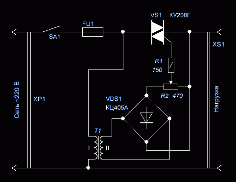
3.1 Voltage regulator on thyristor КУ201К
3.2 Powerful controlled thyristor rectifier
Conclusion
Literature
Introduction
In this paper, several variants of devices are considered, where thyristor elements are used as voltage regulators and as rectifiers. Theoretical and practical descriptions of the operation principle of thyristors and devices, the circuits of these devices are given.
A controlled rectifier on thyristors - elements with a large gain in power, allows to obtain large currents in the load with a negligible power spent in the thyristor control circuit.
In this paper, two variants of such rectifiers are considered that provide a maximum current in a load up to 6 A with a voltage regulation limit of 0 to 15 V and from 0.5 to 15 V and a device for adjusting the voltage on an active and inductive load powered from the network alternating current voltage 127 and 220 V with the adjustment range from 0 to the rated voltage of the network.
Chapter 1. The concept of thyristor. Types of thyristors. Operating principle
1.1 Definition, types of thyristors
A thyristor is a semiconductor device based on a four-layer structure capable of switching from a closed state to an open state and vice versa. Thyristors are designed for key control of electrical signals in open-close mode (controlled diode).
The simplest thyristor is a dinistor - an uncontrolled switching diode, which is a four-layer structure of the type p-n-p-n (Figure 1.1.2). Here, as with other types of thyristors, the extreme n-p-n junctions are called emitter, and the average p-n-junction is a collector one. The internal regions of the structure that lie between the transitions are called bases. The electrode that provides electrical connection to the external n-region is called the cathode, and with the external p-region - the anode.
Unlike asymmetrical thyristors (dinistors, trinistors) in symmetric thyristors, the reverse branch of the current-voltage characteristic is a straight branch. This is achieved by the counter-parallel inclusion of two identical four-layer structures or the use of five-layer structures with four p-n-junctions (triacs).
Fig. 1.1.1. Designations on the schemes: a) triac b) dinistor c) trinistor.
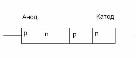
Fig. 1.1.2 The structure of the diacyster.

Fig. 1.1.3. The structure of the trinistor.
1.2 Principle of operation
When the dynistor is switched on according to the scheme shown in Fig. 1.2.1, the collector p-n junction is closed, and the emitter junctions are open. The resistance of the open transitions is small, so almost all the voltage of the power supply is applied to the collector junction, which has a high resistance. In this case, a small current flows through the thyristor (section 1 in Figure 1.2.3).
Fig. 1.2.1. Scheme of inclusion in the circuit of an uncontrolled thyristor (dinistor). 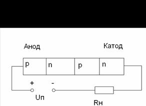
Fig. 1.2.2. Scheme of inclusion in the chain of a controlled thyristor (trinistor). 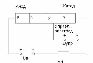
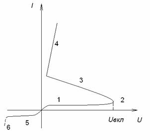
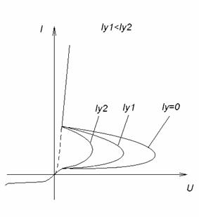
Fig.1.2.3. Volt-ampere characteristic of a dynistor.
Fig.1.2.4. Volt-ampere characteristic of the thyristor.
If the voltage of the power supply is increased, the thyristor current increases slightly, until this voltage approaches a certain critical value equal to the switching voltage Uin. At a voltage Uv in a dynistor conditions are created for the avalanche propagation of charge carriers in the region of the collector junction. There is a reversible electrical breakdown of the collector junction (section 2 in Figure 1.2.3). In the n-region of the collector transition, an excessive electron concentration is formed, and in the p-region there is an excess concentration of holes. With an increase in these concentrations, the potential barriers of all transitions of the dynistor are reduced. The injection of carriers through the emitter junctions increases. The process is avalanche-like and is accompanied by a switching of the collector transition to an open state. Current growth occurs simultaneously with a decrease in the resistance of all areas of the device. Therefore, an increase in the current through the device is accompanied by a decrease in the voltage between the anode and the cathode. On the I-V characteristic this section is designated by the numeral 3. Here the device has a negative differential resistance. The voltage across the resistor increases and the diodistor switches.
After the transition of the collector transition to the open state, the current-voltage characteristic has the form corresponding to the direct branch of the diode (section 4). After switching the voltage on the dinistor is reduced to 1 V. If you continue to increase the voltage of the power supply or to decrease the resistance of the resistor R, then there will be an increase in the output current, as in the conventional circuit with a diode on direct connection.
When the supply voltage decreases, the collector junction resistance is restored. The recovery time of the resistance of this transition can be tens of microseconds.
The voltage Uc at which an avalanche current increase begins, can be reduced by introducing non-principal charge carriers in any of the layers adjacent to the collector junction. Additional charge carriers are introduced into the thyristor by an auxiliary electrode fed from an independent control voltage source (Upr). A thyristor with an auxiliary control electrode is called a triode, or trinistor. In practice, when using the term "thyristor" is meant the element. The circuit for switching on such a thyristor is shown in Fig. 1.2.2. The possibility of reducing the voltage U with increasing control current, shows a family of I-V characteristics (Figure 1.2.4).
If a supply voltage opposite to the polarity is applied to the thyristor (Figure 1.2.4), the emitter junctions will be closed. In this case, the VAC of the thyristor resembles the reverse branch of the characteristic of an ordinary diode. At very high reverse voltages, an irreversible breakdown of the thyristor is observed.
In the schemes and technical documentation, various terms and signs are often used, but not all novice electricians know their meaning. We suggest discussing what power thyristors are for welding, their operation principle, characteristics and marking of these devices.
Many people saw thyristors in the garland "Running Fire", this is the simplest example of the described device and how it works. A silicon rectifier or thyristor is very similar to a transistor. This is a multilayer semiconductor device, the main material of which is silicon, most often in a plastic casing. Due to the fact that its operating principle is very similar to a rectifying diode (AC rectifiers or dinistors), on circuits the designation is often the same - it is considered an analog of a rectifier.
Photo - Scheme of a garland running fire
There are:
- ABB lockable thyristors (GTO),
- standard SEMIKRON,
- powerful avalanche type TL-171,
- optocouplers (for example, TO 142-12.5-600 or MTO 80 module),
- symmetrical TS-106-10,
- low-frequency MTT,
- triac BTA 16-600B or BT for washing machines,
- frequency TBC,
- foreign TPS 08,
- TYN 208.
But at the same time for transistors such as IGBT or IGCT for high-voltage apparatuses (furnaces, machines, other automation of production).
Photo - Thyristor
But, unlike the diode, which is a two-layer (PN) three-layer transistor (PNP, NPN), the thyristor consists of four layers (PNPN) and this semiconductor device contains three p-n junctions. In this case, the diode rectifiers become less efficient. This is well demonstrated by the control circuit for thyristors, as well as any reference book of electricians (for example, in the library it is possible to read the book of the author Zamyatin free of charge).
A thyristor is a unidirectional AC converter, that is, it conducts a current in only one direction, but unlike a diode, the device can be made to operate as an open circuit switch or as a rectifying DC diode. In other words, semiconductor thyristors can only work in switching mode and can not be used as amplification devices. The key on the thyristor is unable to switch to the closed position.
The silicon controlled rectifier is one of several power semiconductor devices together with triacs, AC diodes and unijunction transistors, which can very quickly switch from one mode to another. Such thyristor is called high-speed. Of course, the instrument class plays an important role here.
Application of thyristor
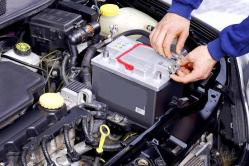
The purpose of thyristors can be very different, for example, a self-made welding inverter on thyristors is very popular, charger for the car (thyristor in the power supply) and even the generator. Due to the fact that the device itself can pass both low-frequency and high-frequency loads, it can also be used for a transformer for welding machines (such details are used on their bridge). To control the work of the part in this case, a voltage regulator is needed on the thyristor.
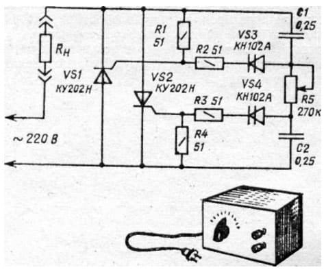
Photo - Thyristor application instead of LATR
Do not forget about thyristor ignition for motorcycles.
Description of construction and principle of operation
The thyristor consists of three parts: "Anode", "Cathode" and "Input", consisting of three p-n jumps, which can be switched from the "ON" and "OFF" positions at a very high speed. But at the same time, it can also be switched from the "ON" position with different time duration, i.e., during several half-periods, to deliver a certain amount of energy to the load. The operation of the thyristor can be better explained if it is assumed that it will consist of two transistors connected to each other as a pair of complementary regenerative switches.
The simplest chips show two transistors that are combined in such a way that the collector current, after the "Start" command, is fed to the NPN of the transistor TR 2 channels directly into the PNP transistor TR 1. At this time, the current from TR 1 enters channels in the bases of TR 2. These two interconnected transistors are arranged so that the emitter base receives a current from the collector-emitter of the other transistor. This requires parallel placement.
![]()
Photo - Thyristor КУ221ИМ
Despite all security measures, the thyristor can involuntarily move from one position to another. This is due to a sharp current jump, temperature difference and other various factors. Therefore, before you buy a thyristor KU202N, T122 25, T 160, T 10 10, you need not only test it with a tester (call), but also get acquainted with the parameters of the work.
Typical thyristor volt-amps
To begin discussion of this complex topic, review the scheme of the I-V characteristics of the thyristor:
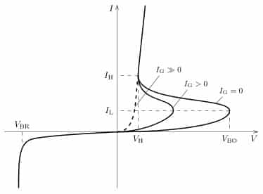
Photo - characteristic of thyristor CVC
- The segment between 0 and (Vob, IL) completely corresponds to the direct locking of the device;
- In section Vvo the "ON" position of the thyristor is realized;
- The segment between the zones (Vbo, IL) and (VH, IN) is the transient position in the switched on state of the thyristor. It is in this area that the so-called dinistor effect occurs;
- In turn, the points (Vh, In) show on the graph a direct opening of the device;
- Points 0 and Vbr are a section with a thyristor locking;
- After this, the segment Vbr follows - it indicates the reverse breakdown mode.
Naturally, modern high-frequency radio components in the circuit can affect the current-voltage characteristics in negligible form (coolers, resistors, relays). Also, symmetric photothyristors, SMD diodes, opti-thyristors, triodes, optocouplers, optoelectronic and other modules can have other I-V characteristic.
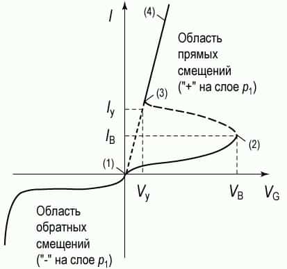
Photo - VAC of thyristor
In addition, we draw your attention to the fact that in this case, the protection of devices is carried out at the input of the load.
Thyristor test
Before you buy the device, you need to know how to check the thyristor with a multimeter. Connect the measuring device only to the so-called tester. The scheme by which this device can be assembled is presented below:
Photo - thyristor tester
According to the description, a positive voltage must be applied to the anode, and negative voltage to the cathode. It is very important to use a value that corresponds to the resolution of the thyristor. The figure shows resistors with a nominal voltage of 9 to 12 volts, which means that the voltage of the tester is slightly higher than the thyristor. After you have collected the device, you can start checking the rectifier. It is necessary to press the button, which gives the impulse signals for switching on.
Checking the thyristor is very simple, on the control electrode the button is briefly applied to the opening (positive with respect to the cathode). After this, if the thyristors catch fire running lights, then the device is considered non-working, but powerful devices do not always react immediately after the load comes.
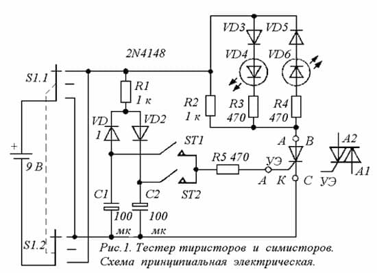
Photo - circuit of a tester for thyristors
In addition to testing the instrument, it is also recommended to use special controllers or a control unit for thyristors and triacs of OWEN BUST or other brands, it works in much the same way as a thyristor power regulator. The main difference is a wider range of stresses.
Video: the principle of the thyristor
Specifications
Consider technical specifications thyristor series KU 202e. In this series, domestic low-power devices are presented, the main use of which is limited to household appliances: it is used for the operation of electric furnaces, heaters, etc.
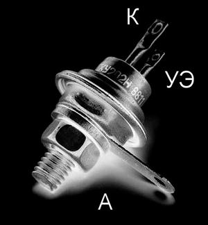
The figure below shows the pinout and the main thyristor components.

Photo of the 202
- Set reverse voltage in open condition (max) 100 V
- Voltage in closed position 100 V
- Pulse in open position - 30 A
- Repetitive pulse in the open position 10 A
- Average stress<=1,5 В
- Non-releasing voltage\u003e = 0.2 V
- Set current in open position<=4 мА
- Reverse current<=4 мА
- A gate current of a constant type<=200 мА
- Installed DC voltage<=7 В
- Switch-on time<=10 мкс
- Turn-off time<=100 мкс
The device is turned on within microseconds. If you need to replace the described device, then consult with the seller-consultant of the electric shop - he will be able to pick up an analogue according to the scheme.
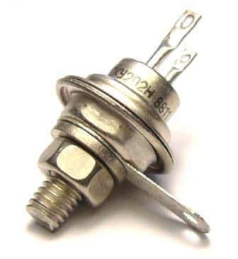
Photo - thyristor ku202n
The price of a thyristor depends on its brand and characteristics. We recommend buying domestic appliances - they are more durable and have an affordable price. In natural markets, you can buy a high-quality powerful converter up to hundreds of rubles.
Principle of thyristor operation |
Absolutely any thyristor can be in two stable states - closed or is open
In the closed state it is in a state of low conductivity and the current is almost not flowing in the open, on the contrary the semiconductor will be in a state of high conductivity, the current passes through it practically without resistance
We can say that the thyristor is an electric power controlled key. But in fact the control signal can only open the semiconductor. To lock it back, it is necessary to fulfill the conditions aimed at reducing the forward current to almost zero.
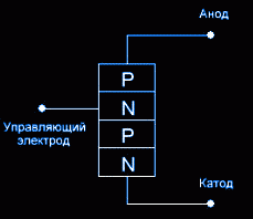
Structurally thyristor represents a sequence of four layers p and n type, which form the structure p-n-p-n and connected in series.

One of the extremes to which the positive pole of the power is connected is called anode, p-type
Another, to which a negative voltage pole is connected, is called cathode, - n of type
Control electrode is connected to the inner layers.
In order to understand the operation of the thyristor, we consider several cases, first: no voltage is applied to the control electrode, the thyristor is connected according to the dinistor circuit - the positive voltage is applied to the anode, and the negative voltage is applied to the cathode, see the figure.
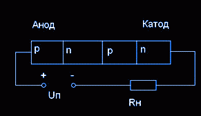
In this case, the collector p-n junction of the thyristor is in the closed state, and the emitter is open. Open transitions have a very low resistance, so almost all the voltage from the power source is applied to the collector junction, because of the high resistance of which the current flowing through the semiconductor device has a very low value.
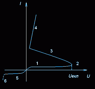
On the I-V curve, this state is actual for the section marked with a digit 1 .
When the voltage level is increased, the thyristor current hardly increases until a certain time. But reaching a conditional critical level - switching voltage U on, in the dynistor there are factors in which the collector transition begins a sharp increase in free charge carriers, which almost immediately carries avalanche. As a result, a reversible electrical breakdown occurs (point 2 in the figure shown). AT p- area of the collector transition appears an excess zone of accumulated positive charges, in n-oblast, on the contrary, there is an accumulation of electrons. An increase in the concentration of free charge carriers leads to a drop in the potential barrier in all three transitions, and injection of charge carriers begins through the emitter junctions. The avalanche-like character is even stronger, and leads to a switching of the collector junction in the open state. At the same time, the current in all regions of the semiconductor increases, resulting in a voltage drop between the cathode and the anode, shown in the graph above the segment marked with the number three. At this point in time, the dinistor has a negative differential resistance. On the resistance Rn The voltage increases and the semiconductor switches.
After the opening of the collector junction, the VAC of the dinistor becomes the same as on the straight branch - segment # 4. After switching the semiconductor device, the voltage drops to one volt. In the future, increasing the voltage level or reducing the resistance will lead to an increase in the output current, one-on-one, as well as the operation of the diode when it is directly switched on. If the level of the supply voltage is lowered, then the high resistance of the collector junction is almost immediately restored, dinistor is closed, current drops sharply.
Switching voltage U on, it is possible to adjust, by adding to any of the intermediate layers, near to the collector junction, non-primary charge carriers for it.
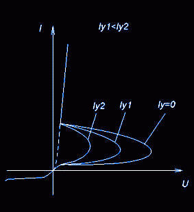
To this end, a special control electrode, fed from an additional source, from which the control voltage follows - U упр. As can be clearly seen from the graph - with increasing U, the turn-on voltage decreases.
Main characteristics of thyristorsU on switching voltage - with it, the thyristor switches to an open state
U o6p.max - a pulsed repeated reverse voltage with it occurs an electrical breakdown of the p-n junction. For many thyristors, the expression U o6p.max. = U on
I max - the maximum permissible current
I Wed - average current for the period U np - direct voltage drop with open thyristor
I o6p.max - reverse maximum current starting flowing with application U o6p.max, due to the motion of minority charge carriers
I hold holding current - the value of the anode current at which the thyristor is locked
P max - maximum power dissipation
t off - tripping time necessary for locking the thyristor
Lockable thyristors - has a classical four-layer p-n-p-n structure, but at the same time has a number of design features that give such functionality as complete controllability. Due to this effect from the control electrode, the locked thyristors can go not only to the open state from the closed one, but also from the open to the closed one. To do this, a voltage is applied to the control electrode, which is opposite to that previously opened by the thyristor. To lock the thyristor on the control electrode, a powerful but short pulse of negative current follows. When using lockable thyristors, it should be remembered that their limiting values are 30% lower than those of conventional ones. In circuitry, lockable thyristors are actively used in the role of electronic keys in converter and impulse technology.
Unlike their four-layered relatives - thyristors, they have a five-layer structure.
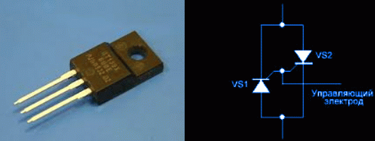
Due to this semiconductor structure, they are able to pass current in both directions - from both the cathode to the anode and from the anode to the cathode, and the voltage of both polarities is applied to the control electrode. Due to this property, the current-voltage characteristic of the triac is symmetrical in both coordinate axes. You can find out about the work of the triac from the video lesson, following the link below.
The principle of triac operation
If the standard thyristor has an anode and a cathode, then the electrodes of the triac can not be described in this way, because each electrode electrode is both an anode and a cathode simultaneously. Therefore, the triac is capable of transmitting current in both directions. That's why it works perfectly in alternating current circuits.
A very simple circuit that explains the principle of the triac is the regulator of the triac power regulator.
After applying voltage to one of the outputs of the triac, an alternating voltage is applied. A negative control voltage is applied to the electrode, which is the controller from the diode bridge. When the switching threshold is exceeded, the triac opens and the current flows to the connected load. At the time when the polarity of the voltage changes at the input of the triac, it is locked. Then the algorithm repeats.
The higher the level of the control voltage, the faster the triac triggers and the duration of the pulse on the load increases. When the level of the control voltage decreases, the duration of the pulses on the load also decreases. At the output of the triac controller, the voltage will be a sawtooth shape with an adjustable pulse width. Thus, by adjusting the control voltage, we can change the brightness of the incandescent lamp or the temperature of the soldering iron tip connected as a load.
So the triac is controlled by both negative and positive voltage. Let's highlight its disadvantages and advantages.
Pros: low cost, long service life, lack of contacts and, as a result, lack of sparking and bounce.
Cons: sensitive enough to overheating and it is usually mounted on a radiator. It does not work at high frequencies, since it does not have time to switch from an open state to a closed one. Reacts to external noise causing false triggering.
We should also mention the features of mounting triacs in modern electronic equipment.
At low loads or if short pulse currents flow in it, installation of triacs can be carried out without a heat sink. In all other cases - its presence is strictly necessary.
To the heat sink the thyristor can be fixed with a fixing clamp or screw
To reduce the probability of false triggering due to noise, the length of the wires should be minimal. For connection, it is recommended to use shielded cable or twisted pair.
Or optotiristorov specialized semiconductors, the design feature of which is the presence of a photocell, which is the control electrode.
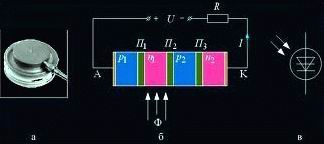
A modern and promising variety of triac is the optosymistor. Instead of a control electrode in the case there is an LED and control is by changing the supply voltage on the LED. When the light output of the bottom power hits the photocell switches the thyristor to the open position. The most basic function in the opto-resistor is that there is a complete galvanic isolation between the control circuit and the power circuit. This creates simply an excellent level and reliability of the design.
Power keys. One of the main factors affecting the relevance of such schemes is the low power that the thyristor can dissipate in switching circuits. In the locked state, the power is practically not consumed, because the current is close to zero values. And in the open state the power dissipation is low due to low voltage values
Threshold devices - they realize the main property of thyristors - open when the voltage reaches the desired level. This is used in power phase regulators and relaxation generators
For interruption and on-off locking thyristors are used. True, in this case, the schemes need some refinement.
Experimental devices - they use the thyristor property to have a negative resistance, while in transient mode
Principle of operation and properties of dinistor, circuits on dinistors |
Dinistor is a kind of semiconductor diodes belonging to the class of thyristors. The dinistor consists of four regions of different conductivity and has three p-n junctions. In electronics, he found a rather limited application, walking it can be found in the construction of energy-saving lamps under the socle E14 and E27, where it is used in startup circuits. In addition, it is found in ballasts of fluorescent light bulbs.
Thyristor is an electronic power partially controlled key. This device, with the help of the control signal, can only be in a conducting state, that is, be switched on. In order to turn it off, special measures must be taken to ensure that the forward current drops to zero. The principle of operation of the thyristor is in one-sided conductivity, in a closed state it can withstand not only the direct voltage, but also the reverse voltage.
Properties of thyristors
By their quality, thyristors belong to semiconductor devices. In their semiconductor plate there are adjacent layers with different types of conductivity. Thus, each thyristor is an instrument having a four-layer structure pn-pn.
The extreme pole of the p-structure connects the positive pole of the voltage source. Therefore, this area is called the anode. The opposite region of the n-type, where the negative pole is connected, is called the cathode. The output from the inner region is carried out using a p-control electrode.
The classical thyristor model consists of two, having a different degree of conductivity. In accordance with this scheme, the base and collector of both transistors are connected. As a result of this connection, each transistor base is powered by the collector current of the other transistor. Thus, a chain with positive feedback is obtained.
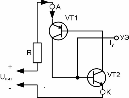
If there is no current in the control electrode, the transistors are in the closed position. Current flow through the load does not occur, and the thyristor remains closed. When the current is applied above a certain level, positive feedback comes into play. The process becomes avalanche-like, after which both transistors are opened. Eventually, after the thyristor is opened, its stable state sets in, even if the current is cut off.
Thyristor operation with direct current
Considering an electronic thyristor whose operation principle is based on one-way current motion, it should be noted that it works at a constant current.
A conventional thyristor is turned on by applying a current pulse to the control circuit. This feed is carried out from the side of positive polarity, opposite, relative to the cathode.
During start-up, the duration of the transient process is determined by the nature of the load, the amplitude and the speed at which the control current pulse rises. In addition, this process depends on the temperature of the internal structure of the thyristor, the load current and the applied voltage. In the circuit where the thyristor is installed, there should not be an unacceptable rate of voltage growth, which can lead to its spontaneous inclusion.