Antipyretics for children are prescribed by a pediatrician. But there are situations of emergency care for fever, when the child needs to give the medicine immediately. Then the parents take responsibility and apply antipyretic drugs. What is allowed to give to infants? How can you bring down the temperature in older children? Which medications are the safest?
Page 1
AC converters and frequency converters, with which alternating current (single- or multi-phase) is converted to a current of a different frequency or voltage.
AC current converters are manufactured by the modern electrotechnical industry in two basic design versions: in the form of frequency converters, powered from a three-phase alternating voltage network, and in the form of autonomous voltage inverters powered from the network constant voltage. Frequency converters include a power rectifier unit, a link direct current and a stand-alone voltage inverter. Typically, frequency converters are used in single-motor drive systems. On the basis of autonomous voltage inverters, powered by a common rectifier (rectification / recovery) unit, economically efficient multi-motor drive systems are implemented.
AC to DC converter.
AC-to-DC converters can be divided into two groups according to the principle of their operation: a) rotating converters, such as motor generators and monocular umformers, and b) stationary ones - mercury rectifiers.
AC-DC converters in recent years are almost universally served by small-sized, most economical silicon rectifiers.
RECTIFIER, AC-to-current converter consisting of one or more valves.
| The scheme of the bridge digital ohmmeter. |
The device has an AC-to-DC converter. There is an output of the binary-coded decimal code.
The stations are a regulated single-phase thyristor converter of alternating current to direct current.
As converters of alternating current in a constant use mercury or semiconductor valves. Mercury valves are usually ignitronic type with water cooling and automatic temperature control. For normal operation of the valve, the temperature of its walls should be maintained within the range of 45 to 50 ° C.
Let us first consider rectifying measuring transducers. They are intended for rectifying (detecting) an alternating current, turning it into a pulsating current, the average value of which is the output value and can be proportional to the peak (amplitude), rms or average rectified values of the input quantity. In accordance with this, the converters themselves are classified as follows: by the parameter of the alternating voltage U x ~ , which corresponds to the output voltage of the detector circuit: converter of peak value, converters of rms and mid-rectified voltage values; according to the scheme of entry: converters with open and closed input for DC voltage ; by the conversion characteristic: linear and quadratic converters.
Peak value converter is a converter whose output voltage directly corresponds to U max or U min (U in or U n). The peak value converter is linear, and it can have an open (figure 2.1a) or closed (Figure 2.1b) input with a constant voltage.
The principle of operation of the voltage peak value converters is to charge the capacitor C through the diode V to the maximum (peak) value U x ~, which is then stored if the discharge time constant of the capacitor C (through the resistor R) is significantly higher than the charging time constant. The polarity of the inclusion of the diode V determines the correspondence of the output voltage U x = either U max (U в) or U min (U н), and the possible pulses U x = are smoothed out by the chain R ф, C ф. If the detector has an open input, U x = is determined by the sum of `U and U in (U n), i.e. corresponds to U max (U min). When the input is closed, U x = corresponds to U in (U n). If U x ~ does not contain a constant component, then the circuits shown in Fig. 2.1, a, b, are identical, and U x = corresponds to U m. In some cases, full-wave doubled voltage detectors are used to directly measure the magnitude of the voltage swing.
Figure 2.1 Schemes of the peak voltage converter:
a) - with an open entrance; b) with a closed entrance.
A significant advantage of the voltage peak-voltage converters is the large input resistance (equal to R / 2 for the circuit in Figure 2.1, a and R / 3 for the circuit in Figure 2.1, b) and the best frequency characteristics in comparison with other types of converters.
RMS Mean-Square Converter is a converter of alternating voltage to direct current (voltage), proportional to U 2 cc. The transformation characteristic in this case must be quadratic, and in the presence of a constant component  a detector with an open input is required.
The converter of the rms value makes it possible to convert the rms value of the variable voltages of the non-sinusoidal form to a constant voltage, since 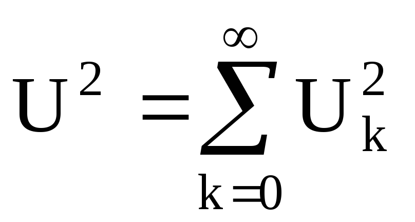 , where U 2 is the rms value of the non-sinusoidal voltage, and U k is the rms value of the harmonic components.
As a nonlinear element of a converter having a quadrature current-voltage characteristic (VAC), for example, one can use the initial section of the current-voltage characteristic of a semiconductor diode. However, this section has a very small extent, and semiconductor devices have a wide range of parameters in this section of the characteristic. Therefore, such converters are built on the basis of a diode chain. Such a chain makes it possible to obtain an I-V characteristic as a result of a piecewise-linear approximation of a parabolic curve. The scheme of a quadratic converter with a diode chain is shown in Fig. 2.2.
The input voltage u in is applied to the broadband transformer T1. With the help of diodes V1 and V2 in the secondary winding, full-wave rectification is performed. The rectified voltage acts on a circuit consisting of a diode chain V1 ... V8, voltage dividers R3 ... R14 and a load resistor R15. Voltage drop on load through low-pass filter  the Z1 frequency is applied to the output of the inverter.
Figure 2.2 Block diagram of the converter
rms value based on the diode chain.
The output voltage is proportional to the average value of the current of the diode circuit. The diode chain has a close to the parabolic voltage-current characteristic. Therefore, the average value of the output voltage is proportional to the square of the rms value of the input voltage.
How does the quadrature current-voltage characteristic work? The voltage dividers R3 ... R14 are connected to a common stabilized voltage source E. The dividers are selected so that the bias voltages U i applied to the diodes satisfy the relation U 1< U 2 < ... < U 6 . Пока входное напряжение цепочки U не достигнет U 1 , все диоды закрыты и начальная часть ВАХ является прямой линией с наклоном, зависящем от сопротивлений резисторов R1, R2 и R15. Когда напряжение U превысит напряжение U 1 , откроется диод V3 и параллельно R2 подключится делитель R3, R4. Крутизна ВАХ на участке от U 1 до U 2 возрастает, ток в цепи станет i = i o + i 1 . Когда выполнится условие U > U 2, the current i = i o + i 1 + i 2 will flow in the converter circuit. The steepness of the current-voltage characteristic will increase with increasing U. Choosing appropriately the resistance of the dividers, one can obtain an I-V characteristic in the form of a broken line approaching a quadratic parabola. Thus, the quadratic characteristic is synthesized from the initial sections of the characteristics of a series of diode cells.
The conversion factor for such a converter is Kv = I / U2, where I is the average value of the output current of the converter, and U is the rms value of the input voltage.
In modern devices, mainly quadratic detectors with thermocouples are used, similar to converters of thermoelectric ammeters. Such a converter is a combination of one or more thermocouples and a heater. The main drawback of them is the quadratic nature of the transformation function. This disadvantage is eliminated by applying a differential circuit of the inclusion of two (or more) thermocouples, as shown in Fig. 2.3.
When a measured voltage U x ~ is applied to the thermal converter TP 1, the output voltage of the TP 1 U 1 = k T U 2 ck.
In addition to the thermal transducer TP 1, the circuit has a second thermal converter TP 2, which is switched on against the TP 1. At TP 2, the feedback voltage is applied, so its output voltage U 2 = k T U 2 3.
Thus, at the input of the UPT, the resultant voltage
U 1 - U 2 = k T (U 2 ck - U 2 3), (2.1)
which corresponds
U 3 = k UPT k T (U 2 ck - U 2 3). (2.2)
If the parameters of the circuit are chosen so that
k UPT k T U 2 3 \u003e\u003e U 3, (2.3)
t 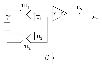 then finally U 3 U ck, i.e. the conversion function will be uniform.
Figure 2.3 Block diagram of the converter
rms voltage
Medium-rectified value converter is a converter of alternating voltage in direct current, proportional to U sv. The current-voltage characteristic of such a converter must have a linear portion within the range of input voltages. An example of such a converter can serve as a full-wave semiconductor rectifier with a low-pass filter. The most common are bridge circuits (Figure 2.4). In the circuit of Fig. 2.4, and the current across the diagonal of the bridge flows in the same direction during both half-periods of the alternating voltage. In the positive half-cycle current flows through the circuit: the upper input terminal - diode V1 - diagonal bridge - diode V4 - lower input terminal; in the negative: the lower terminal - the diode V3 - the diagonal of the bridge - the diode V2 - the upper input terminal.
The direction of the current corresponds to the conducting direction of these diodes. The characteristics of real diodes do not have a strictly linear section, as required by the transformation conditions. The current flowing through the diode with a positive value of the input voltage
 ,
(2.5)
,
(2.5)
where R v (U) is the open diode resistance, which depends on the applied voltage, R is the load resistance.
The initial part of the characteristic is close to quadratic. Therefore, there will be an error, which will be the smaller, the closer to the linear is the diode characteristic.
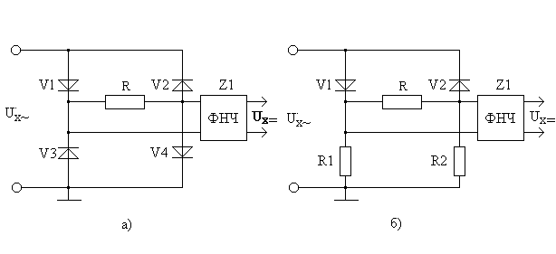
Figure 2.4 Block diagram of the converter
the average rectified value of the voltage.
To improve the linearity of the current-voltage characteristic, a resistor R ext is added to the diagonal of the bridge in series with the resistor R, the resistance of which is much larger than the resistance of the open diode R v (U).
In this case
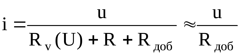 .
(2.6)
.
(2.6)
The dependence of the forward current on the voltage will be close to linear. The decrease in sensitivity due to the inclusion of R ext can be compensated by introducing additional amplification.
The circuit shown in figure 2.4, b, differs from the previous one in that instead of diodes V3 and V4 resistors R1 and R2 are included. In the positive half-cycle of the voltage, the current flows through the diode V1 and the resistor R1. Through the resistor R2 in this half-cycle the current does not flow, at its terminals the voltage is zero. In the negative half-cycle of the voltage, the current flows through the diode V2 and the resistor R2.
The transformation equation for the schemes considered can be expressed as follows:
For the scheme (Figure 2.4a)
U o = K v cv U c =  , for R v1 = R v2 = R v3 = R v4 = R v (2.7)
If R \u003e\u003e R v, then U = U s;
For the circuit (Figure 2.4, b)
U o = K v cv U c =  , with R v1 = R v2 = R v; R1 = R2 = R, (2.8)
If R \u003e\u003e R v, then U = U sv.
The error in conversion is mainly due to the nonlinearity of the current-voltage characteristic of the diode and the influence of the direct resistance of the diode on the current flowing through the rectifying bridge.
It must, however, be added that the linearity of the characteristics of such detectors will be better, the larger U x ~ (for small U x ~ the detector becomes quadratic). Therefore, the detectors of the medium rectified value, as a rule, are used in the voltmeters of the second modification.
The power outage in our homes, alas, becomes a tradition. Is the child going to have to do the lessons with the candle? Or just an interesting film on TV, that would be to watch. All this is fixable, if you have a car battery. It can be assembled to a device called a DC-to-AC converter (in the Western terminology of a DC-AC converter).
Figures 1 and 2 show two main schemes of such converters. The circuit in Fig. 1 uses four powerful transistors VT1 ... VT4 operating in the key mode. In one half-cycle of 50 Hz voltage, transistors VT1 and VT4 are open. The current from the battery GB1 flows through the transistor VT1, the primary winding of the transformer T1 (from left to right according to the scheme) and the transistor VT4. In the second half-cycle the transistors VT2 and VT3 are opened, the current from the battery GB1 goes through the transistor VT3, the primary winding of the transformer TV1 (from right to left according to the scheme) and the transistor VT2. As a result, the current in the winding of the transformer TV1 is obtained alternating, and in the secondary winding the voltage rises to 220 6. When using a 12-volt battery, the coefficient K = 220/12 = 18.3.
A pulse generator with a frequency of 50 Hz can be built on transistors, logic chips and any other element base. Figure 1 shows the pulse generator on the integral timer KR1006VI1 (chip DA1). From the output of DA1, pulses of 50 Hz pass through two inverters on transistors VT7, VT8. From the first of these pulses are fed through the current amplifier VT5 to the pair VT2, VT3, from the second - through the current amplifier VT6 to the pair VT1, VT4. If as VT1 ... VT4 use transistors with a high current transfer ratio ("superbeta"), for example, type KT827B or high fETs, for example, KP912A, the current amplifiers VT5, VT6 can not be set.
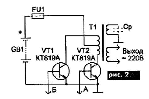
In the circuit in Fig. 2 only two powerful transistors VT1 and VT2 are used, but the primary winding of the transformer has twice as many turns and an average point. The pulse generator in this circuit is the same, the bases of the transistors VT1 and VT2 are connected to the points A and B of the pulse generator circuit in Fig.
The operating time of the converter is determined by the capacity of the battery and the load power. If the discharge of the battery is allowed to be 80% (lead batteries are allowed), the expression for the operating time of the converter looks like:
T (h) = (0,7WU) / P, where W - battery capacity, Ah; U - nominal voltage of the battery, V; P is the load power, W. In this expression, the converter efficiency is also taken into account, making 0.85 ... 0.9.
Then, for example, when using car battery with a capacity of 55 Ah with a nominal voltage of 12 V at a load on a 40 W incandescent lamp, the operating time is 10 ... 12 hours, and when loaded on a 150 W television receiver, 2.5-3 hours.
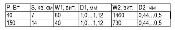
We give the data of the transformer T1 for two cases: for maximum load 40 watts and for a maximum load of 150 watts.
In the table: S - cross-sectional area of the magnetic circuit; W1, W2 - the number of turns of the primary and secondary windings; D1, D2 - diameters of wires of primary and secondary windings.
You can use the ready power transformer, the network winding does not touch it, and the primary winding is mutilated. In this case, after winding, you need to include a network winding in the network and make sure that the voltage on the primary winding is 12 V.
If you use VT1 ... VT4 as a powerful transistor in the circuit in Fig. 1 or VT1, VT2 in the circuit in Fig. 2 of KT819A, the following should be remembered. The maximum operating current of these transistors is 15 A, so if you count on the power of the converter above 150 watts, then either transistors with the maximum current more than 15 A (for example, KT879A), or include two transistors in parallel. With a maximum operating current of 15 A, the power dissipation for each transistor is about 5 watts, whereas without a radiator the maximum dissipated power is 3 watts. Therefore on these transistors it is necessary to put small radiators in the form of a metal plate with the area of 15-20 cm.
The output voltage of the converter is in the form of multi-polar pulses of amplitude 220 V. Such a voltage is quite suitable for supplying various radio equipment, not to mention electric light bulbs. However, single-phase electric motors with a voltage of this form work poorly. Therefore, it is not necessary to include a vacuum cleaner or a tape recorder in such a converter. The output from the position can be found by winding an additional winding on the transformer T1 and loading it onto the capacitor Cp (shown in phantom in Fig. 2). This capacitor is selected so that a loop tuned to a frequency of 50 Hz is formed. With a converter power of 150 W, the capacitance of such a capacitor can be calculated by the formula C = 0.25 / U2, where U is the voltage generated on the additional winding, for example, at U = 100 V, C = 25 μF. At the same time, the capacitor should work at alternating voltage (it is possible to use metal-paper capacitors K42U or similar) and have an operating voltage of at least 2U. Such a circuit takes over part of the converter power. This part of the power depends on the quality factor of the capacitor. So, for metal-paper capacitors, the tangent of the dielectric loss angle is 0.02 ... 0.05, so the efficiency of the converter decreases by about 2 ... 5%.
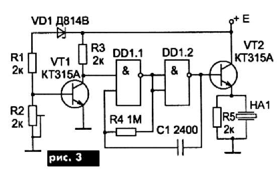
To avoid damage to the battery, the converter does not interfere with the discharge alarm. Simple scheme such an indicator is shown in Fig. The transistor VT1 is a threshold element. While the battery voltage is normal, the transistor VT1 is open and the voltage at its collector is below the threshold voltage of the DD1.1 chip, so the audio signal generator on this chip does not work. When the battery voltage drops to the critical value, the transistor VT1 is locked (the closing point is set by the variable resistor R2), the oscillator on the DD1 chip starts working and the acoustic element HA1 begins to "squeak". Instead of a piezoelement, a dynamic low-power loudspeaker can be used.
After using the inverter, the battery must be charged. For charger it is possible to use the same transformer T1, but the number of turns in the primary winding is not enough, since it is rated at 12 V, and at least 17 V is needed. Therefore, in the manufacture of the transformer, an additional winding for the charger should be provided. Naturally, when charging the battery, the converter circuit must be disconnected.
VD Panchenko, Kiev
A voltage converter is a device that changes the voltage of a circuit. This is an electronic device that is used to change the value of the input voltage of the device. Voltage converters can increase or decrease the input voltage, including changing the value and frequency of the initial voltage.
The need for this device mainly occurs in cases where it is necessary to use an electrical appliance in places where it is impossible to use existing standards or power supply capabilities. Converters can be used as a separate device or be part of UPS systems and sources electric power. They are widely used in many areas of industry, in everyday life and other industries.
Device
To convert one voltage level to another, pulse voltage converters are often used using inductive energy storage devices. According to this, three types of converter circuits are known:
1.Inverting.
2. Increasing.
3. Lowering.
Common to these types of transducers are five elements:
1. Key switching element.
2. Source of power.
3. Inductive energy storage (choke, inductor).
4. The filter capacitor, which is connected in parallel with the load resistance.
5. Blocking diode.
The inclusion of these five elements in different combinations makes it possible to create any of the listed types of pulse converters.
Adjustment of the output voltage level of the converter is provided by changing the width of the pulses that control the operation of the key switching element. Stabilization of the output voltage is created by the feedback method: changing the output voltage creates an automatic change in the width of the pulses.
A typical representative of the voltage converter is also a transformer. It converts an alternating voltage of one value into an alternating voltage of a different value. This property of the transformer is widely used in radio electronics and electrical engineering. The transformer arrangement includes the following elements:
1.Magnitoprovod.
2. Primary and secondary winding.
3. Carcass for windings.
4.Isolation.
5. Cooling system.
6. Other elements (for access to winding leads, mounting, transformer protection and so on).
The voltage that the transformer will produce on the secondary winding will depend on the turns that are present on the primary and secondary windings.
There are other types of voltage converters, which have a different design. Their device in most cases is made on semiconductor elements, since they provide a significant coefficient of efficiency.
Operating principle
The voltage converter produces a supply voltage of the required value from a different supply voltage, for example, to supply certain equipment from the battery. One of the main requirements that are imposed on the converter is to ensure the maximum efficiency.
Conversion of alternating voltage can easily be performed with a transformer, so that such DC converters are often created on the basis of an intermediate conversion of DC voltage to AC.
1. A powerful alternating voltage generator, which is powered by the source of the initial DC voltage, is connected to the primary winding of the transformer.
2. The alternating voltage of the required quantity is removed from the secondary winding, which then is rectified.
3. If necessary, the constant output voltage of the rectifier is stabilized by means of a stabilizer that is connected to the output of the rectifier, or by controlling the parameters of the alternating voltage that is generated by the generator.
4. To obtain high efficiency in voltage converters, generators are used that work in a key mode and generate voltage using logic circuits.
5. The output transistors of the generator, which commute the voltage on the primary winding, pass from the closed state (the current does not flow through the transistor) to the saturation state, where the voltage drops on the transistor.
6. In voltage converters high-voltage sources In most cases, the self-inductance emf is applied, which is created on the inductance in cases of abrupt interruption of the current. The transistor works as a current breaker, and the primary winding of the step-up transformer is inductance. The output voltage is created on the secondary winding and rectified. Such circuits can produce a voltage of up to several tens of kV. They are often used to power cathode ray tubes, kinescopes, and so on. At the same time, the efficiency is higher than 80%.
AT ida
Converters can be classified in a number of ways.
DC voltage converters;
1) voltage regulators;
2) voltage level converters;
3) linear voltage regulator.
AC to DC converters;
1) pulse voltage regulators;
2) power supplies;
3) rectifiers.
DC to AC converters: inverters.
Converters of alternating voltage;
1) variable frequency transformers;
2) frequency converters and voltage forms;
3) voltage regulators;
4) voltage converters;
5) transformers of all kinds.
Voltage converters in electronics in accordance with the design are also divided into the following types:
1. On piezoelectric transformers.
2.Autogenerator.
3. Transformer with pulsed excitation.
4. Impulse power supplies.
5. Impulse converters.
6. Multiplexer.
7. With switched capacitors.
8. Transformerless capacitor.
Features
1. In the absence of restrictions on volume and mass, as well as with a high value of the supply voltage, the converters are rationally used on thyristors.
2. Semiconductor converters on thyristors and transistors can be adjustable and unregulated. In this case, adjustable converters can be used as stabilizers for AC and DC voltage.
3. According to the method for exciting oscillations in the device, there may be circuits with independent excitation and self-excitation. Schemes with independent excitation are performed from a power amplifier and a master oscillator. Pulses from the output of the generator are sent to the input of the power amplifier, which allows you to control it. Schemes with self-excitation are impulse self-oscillators.
Application
1.For the distribution and transmission of electrical energy. Generators of alternating current typically generate power of 6-24 kV at power plants. To transfer energy over long distances, it is advantageous to use a higher voltage. As a consequence, transformers are put at each power station to increase the voltage.
2.For various technological purposes: electrothermal installations (electric furnace transformers), welding (welding transformers) and so on.
3.For feeding various circuits;
1) automation in telemechanics, communication devices, electrical appliances;
2) radio and television equipment.
For separation electrical circuits These devices, including the matching of voltages and so on. Transformers used in these devices, in most cases, have low power and low voltage.
4. Voltage converters of almost all types are widely used in everyday life. Power units of many household appliances, complex electronic devices, inverter units are widely used to provide the required voltage and provide autonomous power supply. For example, it can be an inverter that can be used for an emergency or backup power source for household appliances (TV, power tools, kitchen appliances, etc.) consuming AC 220 volts.
5. The most expensive and in demand in medicine, energy, military, science and industry are converters that have an output alternating voltage with a pure form of a sinusoid. This form is suitable for the operation of devices and instruments that have an increased sensitivity to the signal. These include measuring and medical equipment, electric pumps, gas boilers and refrigerators, that is, equipment, which includes electric motors. Converters are often needed to extend equipment life.
Advantages and disadvantages
The advantages of voltage converters include:
1. Providing input and output current control. These devices transform AC into DC, serve as DC voltage distributors and transformers. Therefore, they can often be found in production and everyday life.
2. The design of most modern voltage converters has the ability to switch between different input and output voltages, including the implementation of adjustment of the output voltage. This allows you to select a voltage converter for a specific device or a connected load.
3.Compactness and ease of household voltage converters, for example, automotive converters. They are miniature and do not take up much space.
4.Economy. The efficiency of the voltage converters reaches 90%, which significantly saves energy.
5.Convenience and universality. Converters allow you to connect quickly and easily any electrical appliance.
6.Ability to transmit electricity over long distances due to increased voltage and so on.
7. Ensuring the reliable operation of critical nodes: security systems, lighting, pumps, heating boilers, scientific and military equipment and so on.
The disadvantages of voltage converters include:
1.Voschimchivost converters of voltage to high humidity (except transducers, specially designed for work on water transport).
2. They take some space.
3. Comparatively high price.