Antipyretics for children are prescribed by a pediatrician. But there are situations of emergency care for fever, when the child needs to give the medicine immediately. Then the parents take responsibility and apply antipyretic drugs. What is allowed to give to infants? How can you bring down the temperature in older children? Which medications are the safest?
Dear guests of the site "Notes of an electrician".
We have already devoted a lot of articles to the topic of electricity metering, but there was not enough time to sort out the device and the principle of the electricity meter operation.
Therefore, today's article is devoted to the principle of operation of single-phase and three-phase meters electric power.
As you already know, electricity meters according to the principle of operation are divided into 2 types:
- induction
- electronic
Let's consider in more detail the principle of operation of each type of counters.
Principle of operation of the induction electric meter
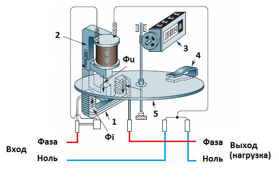
1 - current or series winding (coil)
2 - a parallel coil (winding) or a voltage coil
3 - Counting mechanism in the form of worm gear
4 — permanent magnet to create braking and ride smoothness
5 - aluminum wheel
Фi - magnetic flux, which is generated by the load current
Fu is the magnetic flux generated by the current in the voltage coil
The electricity meter consists of 2 coils (windings): a voltage coil and a current coil, the electromagnets of which are located at an angle of 90 ° relative to each other in space. In the gap between these electromagnets there is an aluminum disk, which is attached to the bearings and thrust bearings from the lower and upper sides. A worm is installed on the disk axis, which transmits the rotation through the gears to the counting mechanism (drum).
The current coil is connected in series in series and consists of a small number of turns. This coil is wound up with a thick wire, correspondingly, to the direct rated current of the electricity meter.
The voltage coil is connected to the circuit in parallel and consists of a large number of turns. It is wound with a thin wire with a diameter of about 0.06 to 0.12 (mm).
When an alternating voltage is applied to the voltage coil and when the load current flows through the current coil, alternating magnetic fluxes Φi and Φu are induced in the gap, which induce eddy currents in the aluminum disk. When these flows and eddy currents interact in the disk, a torque arises - the disc starts to rotate.
The number of revolutions of an aluminum disk for a certain time - this will be our consumed electricity.
If the load current is increased (for example, we added additional load to the network), a larger torque will appear in the coil and the disk will rotate faster.
In the electronic power meter, the converter converts the input analog signals from the current and voltage sensors into a digital pulse code. This code is fed to the microcontroller, where it is decoded and calculated, and then gives the amount of electricity consumed to the meter's display.
P.S. Thank you for attention. The author of the site "Notes electrician."
Electric meter, more precisely - the meter of electric energy consumption is a special device designed to account for the electricity consumed by the load. By its technical idea, it is a combination of a meter of consumed electrical energy with a counting mechanism that displays the readings. There are electric counters for measuring the energy of a constant or alternating current. AC power meters are single-phase and three-phase. According to the principle of action electric counters can be inductive and electronic.
A brief history of creating an electric meter
In 1885, the Italian Galileo Ferraris (1847-1897) made an interesting observation of the rotation of a solid rotor in the form of a metal disk or a cylinder under the influence of two alternating current fields that do not coincide in phase. This discovery served as a starting idea for creating an induction motor and simultaneously opened the possibility of developing induction counter.
The first counter of this type was created in 1889 by the Hungarian Otto Titus Blati, who worked at the Ganz plant in Budapest, Hungary. They patented the idea electric meter for alternating currents (patent issued in Germany, No. 52.793, patent received in the USA, No. 423.210).
In such a device, Blati was able to get an internal phase shift of almost 90 °, which allowed the meter to display the wat watches accurately enough. In the electric meter of this model, a brake permanent magnet was already used, providing a wide range of measurements of the amount of energy consumed, and a register of cyclometric type was also used.
Further years were marked by many improvements, manifested in reducing the weight and dimensions of the device, expanding the range of permissible loads, compensating for changes in the value of the load factor, voltage and temperature. It was significantly reduced the friction in the supports of the rotating rotor of the meter by replacing ball bearings with thrust bearings, later double stones and magnetic bearings were used. The period of stable operation of the meter has increased significantly due to the increase technical specifications braking electromagnetic system and the non-use of oil in the rotor supports and the counting mechanism. Much later, a three-phase induction counter was created for industrial consumers, using a combination of two or three measuring systems installed on one, two or even three separate disks.
Scheme for connecting an induction-type counter
The induction type in the general case is extremely simple and consists of two windings (current and voltage) and a terminal block to which their contacts are exposed. The conditional diagram, which connects a single-phase electric meter, in the standard electrical panel of apartment buildings has the following form:
Here, the "A" phase indicates a yellow line, the "B" phase is green, the "C" phase is red, neutral wire "N" - lines of blue color, conductor for grounding "PE" - a line of yellow-green color. The batch switch is now often replaced with a more modern bipolar automatic with overload protection. It should be noted that there is no fundamental difference between the induction-type meter connection circuit and the analogous electronic meter connection circuit.
The schematic diagram for connecting an electrical meter in a three-phase four-wire network with a voltage of 380 volts looks like this:
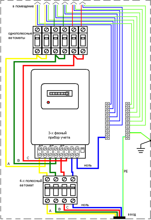
Here, the color designations are the same as the previous meter connection scheme for a single-phase network.
It is important to observe the direct order of the phase sequence three-phase network on the terminal board of the counter. It can be determined using a phase indicator or a VAF device. In a straightforward manner, the alternation of the phases of the stresses is done as follows: ABC, BCA, SAV (if going clockwise). In the reverse order, the alternation of the phases of the voltages is done as follows: ASB, SVA, BAC. At the same time, an additional error is created and the rotor of the induction counter for active energy arises. AT electric meter reactive energy, the reverse order of the alternation of the phases of the load and the voltage causes the rotor to rotate in the opposite direction.
The scheme electrical connections single-phase induction electric counter
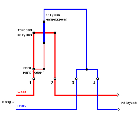
The red line designates the phase wire and the current coil, and the blue color indicates the zero wire and the voltage coil.
The scheme of electrical connections three-phase counter induction type with direct inclusion in a four-wire network of 380 volts:
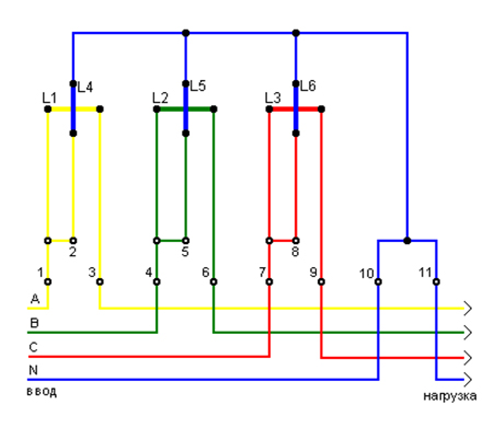
Here: the phase "A" means yellow, the phase "B" - green, the phase "C" - red, zero wire "N" - blue color; L1, L2, L3 - designate the current coils; L4, L5, L6 - designate the voltage coils; 2, 5, 8 - voltage contacts; 1, 3, 4, 6, 7, 9, 10, 11 - contacts for connecting external wiring to a three-phase meter.
The principle of operation and the device of an induction electric meter
The current winding, connected in series with the consumer of electricity, has a small number of turns that are wound with a thick wire corresponding to the rated current of this meter. This provides a minimum of its resistance and making an error in measuring the current.
The voltage winding, connected in parallel with the load, has a large number of turns (8000 - 12000), which are wound with a thin wire, which reduces the consumed no-load current of the meter. When an alternating voltage is connected to it, and the current of the load flows in the current winding, an electromagnetic field, which leads in it so-called eddy currents, closes through an aluminum disk that is a rotor. These currents interact with the electromagnetic field and create a torque that drives the movable aluminum disk.
A permanent magnet, creating a magnetic flux through the counter disk, creates the effect of a braking (counteracting) moment.
The invariance of the rotational speed of the disc is achieved when the balance of the rotating and braking forces is balanced.
The number of rotor revolutions per hour will be proportional to the energy expended, which is equivalent to the fact that the steady-state uniform speed of the disk is proportional to the power consumption if the torque acting on the disk is adequate to the power of the consumer to which the meter is connected.
Friction in the kinematic pairs of the induction counter mechanism creates the appearance of errors in the measuring indications. Especially significant is the effect of friction on small (up to 5-10% of the nominal value) loads for the induction meter, when the magnitude of the negative error can be 12-15%. To reduce the influence of frictional forces in the induction counter, a special device is used, which is called the friction compensator.
Essential parameter the counter of electric energy AC - the sensitivity threshold of the device, which implies the value of the minimum power expressed as a percentage of the nominal value at which the counter rotor starts to rotate steadily. In other words, the sensitivity threshold is the minimum power consumption, which the meter is able to fix.
In accordance with GOST, the sensitivity threshold for induction meters of different accuracy classes should not exceed 0.5 - 1.5%. The sensitivity level is set by the value of the compensating torque and the braking torque, which is created by a special anti-self-propelled device.
How the electronic meter works
Induction meters of electric energy consumption for all their simplicity and low cost have a number of drawbacks, based on the use of mechanical moving elements that have insufficient stability of parameters in the long-term operation of the device. The electronic electricity meter is free from these drawbacks, has a low threshold of sensitivity, higher accuracy of energy consumption measurement.
True, the construction of an electronic meter requires the use of highly specialized integrated circuits (ICs) that can multiply current and voltage signals, form the resulting value in a form convenient for processing by the microcontroller. For example, the chips that convert the active power to the pulse repetition rate. The total number of received pulses, integrated by the microcontroller, is directly proportional to the consumed electricity.
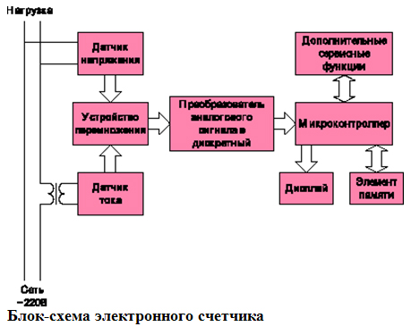
Block diagram of the electronic counter
Equally important for the full operation of the electronic meter is the availability of all kinds of service functions, such as remote access to the meter for remote monitoring of readings, determination of daytime and night energy consumption and many others. The use of the digital display allows the user to programmatically set various output formats, for example, display information on the amount of energy consumed for a certain interval, set different tariffs and the like.
To perform certain non-standard functions, for example, to match signal levels, additional IC will be required. At present, the production of specialized microchips - power converters to a proportional frequency - and specialized microcontroller devices having a similar converter on a single crystal has been launched. But, more often than not, they are too expensive for use in household appliances induction meters. Therefore, many world manufacturers of microcontrollers are developing specialized low-cost microcircuits specifically designed for such applications.
What kind does electrical schematic diagram of the meter on the simplest digital version on the most inexpensive (less dollar) 8-bit microcontroller from Motorola? In this decision all the minimum required functions of the device are implemented. It is based on the use of an inexpensive IC that converts power to the pulse frequency of the type KR1095PP1 and the 8-bit microcontroller MC68HC05KJ1. With this counter architecture, the microcontroller needs to summarize the number of pulses received, display information on the display, and protect the device in various abnormal modes. The described counter is in fact a digital functional analogue of the available mechanical meters, adapted for further improvement.
Electric schematic diagram of the simplest digital electricity meter
Signals equivalent to the voltage and current values in the network are obtained from the sensors and fed to the input of the converter. The microcircuit multiplies the input signals, forming an instantaneous value of the power consumption. This value is fed to the microcontroller, converted to a watt-hour. As the data is accumulated, the meter reading on the LCD changes. The presence of frequent failures of the power supply voltage of the device leads to the need to use EEPROM to ensure the safety of the meter readings. Since supply voltage failures are the most common abnormal situation, such protection is required in any electronic meter.
Electric schematic diagram of the meter (digital calculator) is shown below. Via connector X1, the mains voltage is 220 V and the electrical consumer. Voltage and current sensors form the signals arriving at the chip KR1095P1 of the converter, which has an opto-coupler of the frequency output. The core of the counter is the microcontroller MC68HC05KJ1 manufactured by Motorola, manufactured in a 16-pin package (DIP or SOIC) and equipped with 1.2 KB of ROM and 64 bytes of RAM. To save the accumulated amount of energy consumed during power failures, EEPROM with a small memory capacity of 24С00 (16 bytes) from Microchip is used. The display is a 7-segment 8-bit LCD, which is controlled by any inexpensive microcontroller that communicates with the central microcontroller with data via SPI or I2C protocols and connected via connector X2.
The embedded algorithm of the counter operation required less than 1 Kbyte of memory and less than half of all the I / O ports on the MC68HC05KJ1 microcontroller. Its technical capabilities are sufficient to supplement the meter with some service functions, for example, the possibility of combining meters into a local network via the RS-485 interface. This feature allows you to obtain data on consumed energy in the service center and remotely turn off the electricity if the customer has not made payment. A network containing such meters can be equipped with a residential apartment house. All meter readings via the network will be remotely delivered to the control room.
Of practical interest is the use of a family of 8-bit microcontrollers with a crystal containing a built-in FLASH memory. This allows it to be programmed directly on the assembled board. This also provides protection against hacking code and the convenience of updating the software without performing installation work.
Digital calculator for electronic energy meter
More interesting is the option of an electronic power meter without the use of an external EEPROM and expensive external non-volatile RAM. In this case, it is possible, in the event of an emergency, to record readings and other service information in the internal FLASH memory of the microcontroller. This additionally ensures the required confidentiality of the data, which can not be provided if an external crystal is used that is not protected from unauthorized access by unauthorized persons. Such an electronic electricity meter with any level of complexity and functionality can be created using a Motorola microcontroller from the HC08 family with FLASH memory built into the main crystal.
The implementation of the transition to digital remote automatic means of accounting and control of electricity consumption is a matter of time. Technical and consumer advantages of such systems are obvious. The cost of them will invariably decrease. And even in the case of using the simplest microcontroller, such an electronic energy meter has obvious advantages: high reliability due to the total absence of moving parts; miniature; the possibility of issuing a counter in the building taking into account the interior features in modern residential buildings; increase the interval of verification several times; high maintainability and extreme ease of maintenance and operation. Even small additional hardware and software costs in a simple digital meter can supplement it with a number of service functions that are fundamentally absent in all mechanical electricity meters, for example, the use of a multi-tariff charge for consumed energy, the possibility of implementing automated accounting and control of electricity consumption.
See also diagrams.
We all know why you need an electricity meter - to properly account for electricity consumption. Based on the meter readings, payment is made "for light". In this article, we would like to tell readers about the device and the principle of the electricity meter. For you, we will consider both the electronic model and the old model - the induction one.
Induction
Old electricity meters consist of the following elements:
- Sequential winding, also called a current coil. It consists of several turns of thick wire.
- Parallel winding (voltage coil). Arranged, on the contrary, from a large number of turns of a wire of a small thickness.
- Counting mechanism. It is mounted on the axis of the aluminum disk.
- A permanent magnet, whose function is to brake and ensure a smooth course of the disk.
- Disk made of aluminum. Mounted on bearings and thrust bearings.
As can be seen on the diagram, the device of the induction meter is quite simple. As for the principle of work, it is also uncomplicated. First, the alternating voltage is applied to the parallel winding (voltage coil) and then flows to the second, current coil. Between the two electromagnets of the coils, magnetic eddy currents arise, which, in fact, contribute to the rotation of the disk. The higher the amperage, the faster the disc will spin. In turn, the counting mechanism operates according to the following principle: rotation from the disk is transferred to the drum due to worm gear (this is facilitated by a worm mounted on the disk axis, which transmits rotation through the gear, as seen in the diagram above).
To see how the induction meter works, you can on the video below:
Scheme of operation of the electricity meter of the old type
We draw your attention to the fact that the principle of work single-phase counter electricity of the old sample is similar to the three-phase model.
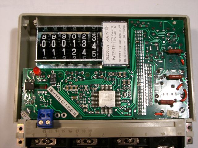
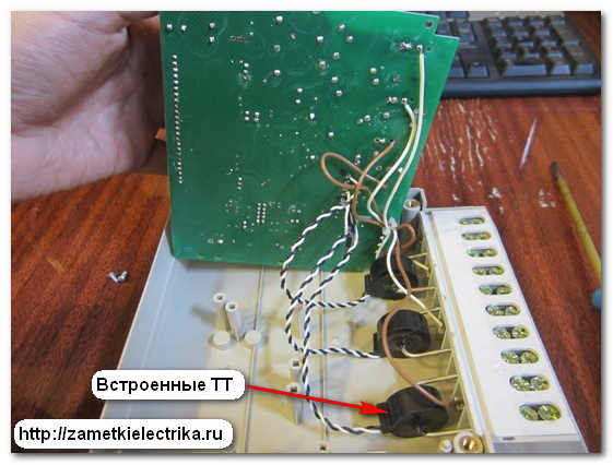
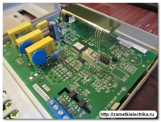
Electronic
In the electronic counter, for example, there is neither a disk nor a worm gear. The device of electricity meters of a new sample is shown on the diagram and the photo below: