Antipyretics for children are prescribed by a pediatrician. But there are situations of emergency care for fever, when the child needs to give the medicine immediately. Then the parents take responsibility and apply antipyretic drugs. What is allowed to give to infants? How can you bring down the temperature in older children? Which medications are the safest?
In the domestic market, the CIP wire (isolated self-supporting cable) came directly from two countries. The suppliers were:
- finnish Nokia Cables;
- a French company under the brand Alkatel.
Wire sip offered by these companies, had significant differences in technical performance from the classic wire.
Self-supporting insulated wire for overhead transmission lines
Russian Electrical Wire
Since 1997, domestic companies "Irkutskkabel" and "Sevkabel" have been producing high-quality electric wire. Good technical characteristics for a short time interval made the wire mesh in demand in everyday life and construction.
The cost of manufacturing such a cable is higher by 20-25% compared to an uninsulated open wire, and its strength and reliability are higher by 60-70%.
In the Russian Federation there is a special program that, in connection with the transfer of all enterprises that are part of RAO UES of Russia, is aimed at electric supply through the air streams with the use of a cable.
Wire sip is indispensable if necessary to transfer and distribute electricity to household networks rated for voltage less than 1 kV (models 1-5), up to 20 kV (sip-3).
SIP cable appearance
Sip cable has the following spheres of use:
- for backbone networks and electric lines;
- for arranging the supply of electricity to homes, any structures for everyday use.
Distinctive characteristics
When using an isolated electrical cable, operating costs are reduced to 70-80 percent. The cable has high reliability, guarantees uninterrupted power supply to the consumer. An isolated self-supporting electrical wire prevents short circuits caused by sticking snow, breakages during the crash of trees, the formation of ice.
Power cable allows you to reduce the cost of installing high-voltage lines. When installing it, you can confine yourself to logging in the forest of a small glade. In the city, the installation of a power line is allowed on the facades of the houses. It is not necessary to mount expensive traverses and insulators, it is possible to combine the suspension on a high-voltage (overhead power transmission line) low voltage, as well as communication lines.
Losses electric power within the line can be reduced several times, replacing the bare wire with a self-supporting electrical cable. Savings are explained by minimal energy losses.
Considering the simplicity of performing assembly activities, it is possible to connect new subscribers without reducing the voltage, significantly reducing the terms of arrangement and maintenance of the electric wire.
The power cable is characterized by high fire safety, since short circuits are not allowed, due to the connection of the phases of the conductors.
The power wiring significantly reduces the number of illegal connections to the line itself, and the loss of electricity is also reduced. You can also save money on repairs, initial installation, operation of such an electric cable.
Characteristics of Species
Power electric wire is equipped with conductive electricity elements directly made of aluminum. The insulation itself is assumed to be light-resistant polyethylene. The zero carrier part is not insulated, it is made of aluminum alloy. The electric wire is produced in accordance with GOST R 52373 (2005).
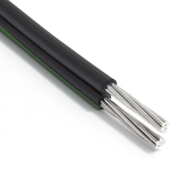
The current-carrying phase conductors of the SIP cable are made of aluminum
The same electrical cable is AXKA. Its conductors are made of aluminum. They are round, multiwire, their number varies in the range of 1-4 pieces. The zero (carrier) part is made of multiwire, round, use an alloy of light aluminum, it is not insulated. For the insulation of the cable, cross-linked light-stabilized polyethylene is used. Isolate the veins with a bright color or a numbered number.

Different types of self-supporting insulated wire
The main insulated elements are twisted around the zero part. Such wires are suitable for the power transmission option (VL), designed for a minimum voltage of 0.6 kV and a nominal frequency of 50 Hz. For the most part, this power cable is mounted for branches to private houses in air atmosphere of II or III class (according to GOST 15150-69). Installation is performed at temperatures not lower than -20 ° C, maximum heating of the electrical wire during use + 90 ° C. Manufacturers give a three-year warranty on electrical wires of this type, which is an indicator of high quality products. The term of continuous service of products is 40 years.
Such an electric wire is equipped with a bearing housing made of an aluminum light alloy. This multiwire wire assumes the right direction of twisting, suitable for VL lines with a minimum voltage of 1kW, frequency of 50 Hz. You can use a cable for overhead lines, as well as for branches to household and commercial buildings, private homes in the air atmosphere. The wire in case of short circuit is designed for maximum heating of 250 ° C. The radius of bending (during installation) is not less than 10 outer diameters of the cable.

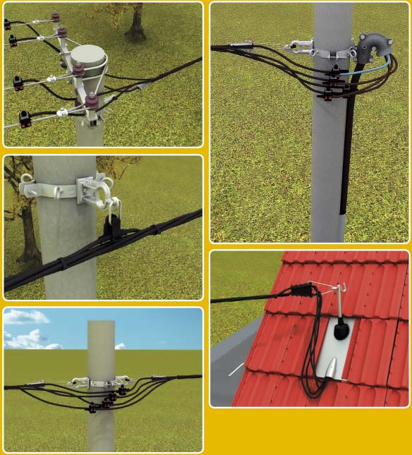
Power line support using CIP cable
The electric wire must comply with the existing GOST R 52373 - 2005, for it an aluminum alloy is used. The cable has a service life of 40 years. The core for such a cable is taken round, multiwire, dense. For insulation use cross-linked polyethylene. This composition is used for household transmission lines with voltage up to 20 kV, frequency 50 Hz. It is designed for 40 years of continuous service.
The electric cable of this type has compacted aluminum conductive current wires. For isolation, special light-stabilized polyethylene is chosen. Number of cores 2-4 pieces. Marking is assumed in digital form or using a variety of colors.

General view and structure of cable SIP-4
The configuration of the cable sip has a certain feature, by which it differs from other cables and wires. Laying of similar wires on the air lines of electric transmissions is possible without preliminary laying of the supporting cables. Variants sip 1 and sip 2 have in the form of the main cable a standard self-supporting vein. Sip 3 and Sip 4 do not assume the presence of a supporting cable.
Installation. Video
About the installation of the SIP wire with the help of jaw clamps is described in this video.
The cable products offered in the modern market are so diverse that an ordinary citizen has a choice problem. It is difficult to make it on your own. It is necessary to pay attention to the strength of the insulation layer. There are several types of wires that differ maximum loads, operating conditions. The advantage of such wires is that you can carry out the installation without special skills.
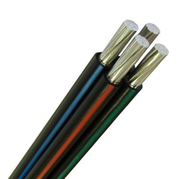
SIP - self-supporting insulated wire, is intended for the transmission of electricity in air electrical networks. At present, SIP has found application both in the main air lines and as branches (entrances to private houses, outbuildings).
 Externally, the SIS is a twisted current-conducting aluminum core covered with insulation made of light-stabilized cross-linked polyethylene. Each vein has a round shape and is twisted from aluminum alloy wires (their number depends on the cross section of the CIP itself), compacted.
Advantages of self-supporting insulated wires:
Significant cost reduction, both for maintenance and installation of lines. This is due to the reliability of the work of the lines - the absence of short circuits when the wires are shredded due to strong wind, foreign objects get by good insulation of veins, "dancing wires" - sticking snow, ice formation. Possibility of installation of self-supporting insulated wire on existing low voltage, high voltage, communication lines. Due to good insulation, electric losses in lines are reduced (due to a strong decrease reactance wires). The possibility of connecting to the line under voltage (if the line is made SIP). The possibility of applying voltage classes of 0.6 / 1 kV and 20 kV in power lines at temperatures from -50 ° C to + 50 ° C. Higher fire safety of self-supporting insulated wire (no wire stranding). A more aesthetic appearance than conventional non-insulated wires (for example, entry into the house, especially if the input is 380V). Insulation SIP, thanks to the use of light-stabilized cross-linked polyethylene is able to withstand the harmful effect of sunlight - ultrafiolet for a long time. The lifetime of the SIP is at least 25 years. |
Stamps SIW:
Their difference is in the design: SIP 1 - the presence of a non-insulated core; SIP 2 - the presence of an isolated carrier neutral; SIP 4 - without a zero core.
SIP 1 - self-supporting wire with aluminum phase conductors, with insulation from light-stabilized thermoplastic polyethylene, with a zero-bearing, non-insulated core made of aluminum alloy.
SIP 1A - self-supporting wire with aluminum conductor conductors, with insulation from light-stabilized thermoplastic polyethylene, with a zero-carrying residential, isolated light-stabilized thermoplastic polyethylene.
SIP 2 - self-supporting wire with aluminum conductor conductors, with insulation made of light-stabilized cross-linked polyethylene, with a zero-carrying bare insulation of aluminum alloy.
SIP 2A - self-supporting wire with aluminum conductor conductors, with light-stabilized cross-linked polyethylene insulation, with an aluminum alloy bearing housing, isolated light-stabilized cross-linked polyethylene.
SIP 2F - self-supporting wire with aluminum conductor conductors, insulated with light-stabilized silanol-crosslinkable polyethylene (PE), carrying a zero non-insulated core of aluminum alloy.
SIP 2AF - the same, but with a carrier of zero residential, isolated light-stabilized silanol-crosslinkable polyethylene (PE), with or without a separator, or without a supporting core.
CIP 4
- wire without a supporting cable, in which all 4 wires of equal cross-section. Fastening of such a wire is carried out in the anchor and in the support clamps immediately for all 4 wires, therefore the total tensile strength and the total permissible load in this wire is greater than in the carrying wire of wires SIP 1A and SIP 2A of a similar section.
The price for CIP 4 is lower than for SIP 1A and SIP 2A due to the fact that the price of aluminum is lower than the price of aluminum alloy. It is worth noting that when twisting wires SIP 4 uses technology that provides a dump of adhered wet snow and ice. The principle of dropping snow is based on the disturbance of the state of unstable equilibrium under the action of an additional load from wet snow.
SIPC 4 with XLPE insulation, has greater resistance to short circuits.
When installing the self-supporting insulated wire, a special fitting is used
Fittings for self-supporting insulated wire
The elements of self-supporting insulated wires (SIP) shown below are only basic, basic elements. With their use, it is possible to perform electrical a private house with the help of CIP.
Anchor bracket It is intended for fastening of anchor clamps of main lines of SIP. Made of aluminum alloy, resistant to low temperature corrosion. Installation anchor brackets produced with the help of banding tape L207 made of stainless steel. |
|
Branch tap. Provides reliable contact due to the design of contact plates of tinned copper, even wires of small cross-sections (1.5-2.5 mm2). It is used for connecting veins with a cross-section of 6-150 mm2 in a trunk with 1.5-6 mm2 cores for both street lighting and electrical input into the house. |
|
Anchor clamp. It is used for fixing insulated conductors on branches to inputs up to 1000V. The clamping body has internal wedges made of thermoplastic, which ensure the compression of the wires of the wire, without damaging its insulation. Made of weatherproof plastic. The clamp loop is strong enough, it is made of hot galvanized steel. |
|
Intermediate clamp It is used for fixing a self-supporting system SIP 4 with 2 or 4 supporting veins on intermediate or corner bearings. Additional wires are laid along the clamp. The casing of the intermediate clamp is made of a material resistant to UV radiation. |
|
Facade fastening. It is a removable clamp, fastened to the wall surface by an insulated dowel. Adjustable depending on the diameter of the wire being laid. Totally made of material, providing double insulation of cores. Does not contain elements that are susceptible to corrosion. |
What is the abbreviation of CIP? This abbreviation stands for - self-supporting insulated wire. It is the wire, not the cable, as some mistakenly call it.
It must be produced in accordance with GOST 31946-2012 ().
The SIP always consists of aluminum conductors or of an aluminum alloy (phase conductors), or a steel core and an aluminum sheath (a zero carrying conductor). CIP wires are never copper. Its minimum cross-section starts from 16mm2.
This is absolutely not a new invention, as some believe, and it has been known for more than 50 years.
For the first time CIP was applied in the countries of North America, and then in Western Europe back in the 1960s.
Advantages of using CIP
 In comparison with bare power lines, a self-supporting insulated wire simply has many advantages:
- high reliability
Due to solid insulation, phase-to-phase short circuits and subsequent wire breaks are eliminated. Accordingly, the line will no longer be observed such a sad picture as the numerous sdalki in spans. 
- It is possible to use supports of smaller overall dimensions
For example, instead of supports CB-110 and SV-95 take stands SV-85. Or even use wooden ones. 
- the distance from SIP to buildings and structures is reduced in comparison with bare HVL-0.4 kV
Accordingly, there are more options for using power lines in dense residential buildings. 
![]()
- Less losses in transmission due to low inductive resistance
For example, for a wire cross-section of 70 mm2, the inductive resistance of SIP is less than 4 times! ![]()

- Using a special tool kit, it is possible to service the SIP under voltage without interrupting the supply of electricity to consumers

- trouble-free operation with proper maintenance from 30 years and more

- there are no extra costs for traverses, insulators, hooks, caps, clamps to traverses
- safety of work near SIP lines of external mechanisms
The likelihood that the truck crane operating in the guard zone of the power line will touch the boom of the wires and will be under voltage at a minimum. 
Kinds and marks of wires SIP
To date, four main SIP systems have been distributed:

In the conductors of SIP there is one uninsulated conductor, which is also a carrier wire at the same time. Another variety of this brand is CIP-1A.

The main difference between SIP-1A and SIP-1 and SIP-2 is the insulation of the wire.
In SIP-1A insulation is cheaper and made of thermoplastic polyethylene, and in SIP-1, SIP-2 made of cross-linked polyethylene with improved qualities of heat resistance. Accordingly, the admissible currents load. 
For power lines up to 35kV inclusive. The wires are no longer twisted into one bundle and run separately for each phase.

Here, all 4 wires carry a mechanical load at the same time. Both the zero and phase conductors are isolated, and the load on them is distributed equally.
Features of different brands of self-supporting insulated wires

Wire SIP 4
 CIP strands consist of twisted aluminum conductors with subsequent consolidation. All cores of the same section and with the same insulation. Each core is covered with insulation from light-stabilized or thermoplastic polyethylene.
SIP marking
Phase marking must be applied to the insulation. It is carried out either with the help of colored longitudinal risks or stripes, or with the help of digital marking.
From the personal experience of operation, I advise you to acquire a SIP with a digital marking, although it is less common.
Once I purchased a wire, where the marking was made with solid, thin color lines. After 3 years of operation, the entire SIP, which hung on the street, which is more than 300 meters, was rendered unusable. 
SIP simply cracked and cracked, it was on the color strip all along the line. The very black isolation was like new. Apparently there was production of a low-quality factory of the manufacturer. But I think that with figures on isolation, this would not happen.
The problem was precisely in a low-quality dye, which had the usual properties and did not protect the wire shell from the ultraviolet effect.
- Possible cross-sections of conductors for SIP-4 from 16 to 150mm2.
- The maximum number of veins in the harness is 6 pieces
All major technical specifications - sections, maximum loads current, resistance, the weight of the wire SIP-4 are presented in the tables below: 

Cold-weathering on SIP wires
 Ice formation and sticking of snow on the wires of SIP-4 is minimized. If wet sleet or ice drips onto the wire, then it automatically resets for a short period of time. This is achieved by disturbing the state of equilibrium from the additional load, in the form of adhered ice and snow.
Here is a short video, clearly showing the glaze formation on the SIP-3 and its absence on the SIP-4, and the wires are suspended on the same supports!
The insulation resistance of SIP-4 should be the same for all conductors and be at least 0.5 mOhm.
The test of SIP 4 is carried out by a megaohmmeter per 1000 volts. All phase conductors are tested between themselves and on a zero vein. High-voltage factory testing of wires is carried out in water, voltage from 2.5 kV to 4 kV, depending on the type of insulated wire. 
Species SIP-4
For increased loads with preservation of the previous section, you can use the SIPS-4 wire. Its insulation can withstand a high heating temperature. Accordingly, the nominal throughput current is thereby increased. The letter "c" means light-stabilized cross-linked polyethylene. 
On sale you can find several types of wires SIP-4. The most common of them are:
- SIPS-4
With insulation from cross-linked polyethylene or more on scientific - weather resistant polyethylene with cross-linked molecular bonds. In addition to the increased current loads, it is also subjected to a higher voltage than other SIP marks.
The high-voltage test for SIP-4 is performed U = 4kV. The remaining brands must withstand a high voltage of at least 2.5 kW. Moreover, SIPS-4 made of cross-linked polyethylene is more stable in its physical properties to punching.
- SIP-4 wire
The letter "n" means non-burning. You need to buy it for installation of indoor insulated wire.
- SIPT-4 wire
The letter "t" is a thermoplastic polyethylene. It means that in the event of a short circuit and heating up to the melting point, the insulation of the core "will not flow", but will pass into a viscous-fluid state. After turning off the short circuit and cooling down, the insulation must regain its shape again.
Wire SIP 1
technical characteristics and differences
 SIP-1 consists of aluminum multiwire current-carrying veins of round shape. The zero core serves as a supporting conductor. It is made of a steel core around which wires of aluminum or aluminum alloy are surrounded by compacted coils.
On top ONLY conductive cores are insulated from light-stabilized polyethylene. The zero vein remains naked, not isolated.
All insulated cores are twisted around zero. Wire SIP-1 can be both two-wire, and four-core, section up to 240mm2. Also, in SIP-1, wires with additional insulated conductors up to 25 mm2 can be woven, for example, for street lighting. 
Wire SIP 2
technical characteristics and differences
 In the CIP-2 wires, the zero core is also made of a steel core with aluminum wires outside. The difference between SIP-2 and SIP-1 is the presence of insulation on a zero-carrying core.For phase conductors, the insulation is the same and is made of light-stabilized cross-linked polyethylene.
Table technical specifications, load currents, weight, active resistance for SIP-2: 
Wire SIP 3
technical characteristics and differences
 SIP-3 is available in sections from 25mm2 to 240mm2. The insulation is made of cross-linked polyethylene. Inside the core there is a steel core, around which aluminum wires are twisted.
Sip-3 designed for suspension on a VL voltage of up to 20 kV, has an insulation thickness of 2.3 mm. For wires designed for installation on a 35 kV overhead line, the insulation is already larger - 3.5 mm thick.
 SIP-5 is very similar to SIP-4. Even a specialist will not immediately distinguish these brands of wires. Its main difference is the isolation of the veins. Namely - silanol-cross-linked light-stabilized polyethylene.
This material has many advantages:
- Heating temperature without loss of basic insulation properties is more - 90-130 degrees for 8 hours.
- The short-time temperature of overheating at a short circuit is 250 degrees.
- This isolation has a "memory". That is, after deformation during compression or overheating, it is able to regain its original state.
- Best resistance to low temperatures. Accordingly, less whimsical when laying in frosts and the risk of damaging the insulation during installation and bending is minimal.

 SIP-5 with the brand "ng" is also available, which means - not combustible. Choose this option of SIP, if you need to bring it inside the house, directly to the panel or to the meter itself.
 As already mentioned, u self-supporting wires a lot of advantages over conventional bare air power lines. And it is not only profitable in terms of reliability, but also economically efficient. Applying new technologies and armature, the lines of lines can be designed quite according to other schemes.
Here is a comparative table of costs for installing an air line 0,4kv with a length of 1km using bare wires and CIP marks of various systems. The analysis was conducted by ZAO SIC "StarInfo" (taken from here).
The table shows the cost as a percentage for each element of the overhead line and directly to the installation itself. And in the end summed up. Again, the percentage shows the difference in the cost of installation of a particular system. The cost of installing an aerial VL-0,4 kV with bare wires, is conditionally taken as 100%.
| Expenses | 4Ax70 | SIP-1 3x70 + 95 | SIP-2 3x70 + 95 | SIP-4 4x70 |
|---|---|---|---|---|
| The wire | 23,4% | 43,24% | 47,28% | 39,45% |
| Supports | 27,78% | 23,39% | 21,51% | 24,39% |
| Linear fittings | 5,42% | 6,27% | 6,29% | 7,89% |
| Preparing the course | 5,42% | 0,93% | 0,85% | 0,97% |
| Installation work | 29,95% | 18,68% | 17,17% | 19,48% |
| Other costs | 8,03% | 7,49% | 6,9% | 7,82% |
| Total | 100% | 100% | 100% | 100% |
| Expenses | 4Ax70 | SIP-1 3x70 + 95 | SIP-2 3x70 + 95 | SIP-4 4x70 |
|---|---|---|---|---|
| The difference in the cost of installation (based on the cost of VL-0,4 kV) |
The design of overhead power lines since the moment of their invention has undergone little change. The basis remains the same: the wires are attached to the insulators. The material for the wires is aluminum, which has low resistivity in combination with low cost. For greater flexibility, the wire for the power line is made of multiwire, and to increase the tensile strength and tensile strength, steel wire is added inside it.
Porcelain is the material for the manufacture of insulators. So that moisture and dust do not stay on them, the surface of the insulators is covered with glaze and finned.
The design of the transmission line is simple, that provided it with wide application, but did not exclude the disadvantages, with the consequences of which electricians have to fight to this day.
- The shape and coating of the insulators do not exclude their breakdown.
- The bird that has sat on the wires for rest becomes the cause of a short circuit.
- The wires are still stretched, which in strong wind leads to their swinging, shlestyvaniyu and short circuit.
- A tree falling on a line leads to a short circuit, sometimes with a wire break.
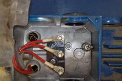
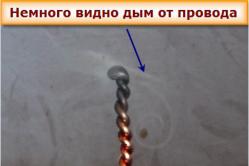
- Connection of outgoing lines to the main line is performed by twisting. Over time, contact in it weakens, heats up and disappears.
- To repair the line or connect to it subscribers need to de-energize it. Otherwise, an electrician at the height of waiting for deadly trouble.
The result of these shortcomings is expensive line maintenance. It is made up of the need:
- constant on-duty watch of the operational-visiting brigades (ATS);
- availability of stock of spare parts (insulators, wires);
- provision of ATS transport for arrival to the accident site, means for lifting to the height (including cars with towers).
Let's add to this that any climb to the support for line repair is work related to risk to life and health. And it requires a high qualification of an electrician, purchased for years. And after hurricanes, heavy snowfalls and icing of wires, power line accidents occur massively. Energy supply companies incur losses from the cessation of supply of electricity to consumers, reinforced by material costs for repair of transmission lines.
CIP - a new word in the design of power lines
The thesis realized in the design of a self-supporting insulated wire: let the wires isolate themselves. But in this case, the requirements for the coating of the SIP conductors differ from those of the power cables:
- mechanical strength;
- resistance to precipitation, temperature fluctuations;
- resistance to ultraviolet light;
- flexibility.
These properties are suitable for thermoplastic or cross-linked light-stabilized polyethylenes. Of these, the insulation of the CIP wires is also made.
Thermoplastic Polymers are known that are capable of repeatedly softening with increasing temperature and returning to the initial state upon its reverse reduction. Crosslinked polyethylene is manufactured using a special technology. With increased pressure, its molecules acquire additional bonds between themselves, as if stitching. This provides the resulting material with not only additional mechanical strength, but also electrical strength. It produces not only SIP wires, but also cables: both low-voltage and high-voltage cables.

But no polymer is able to independently withstand the weight of the prisoner in it. In SIP, this function is implemented in one of the ways:
- one of the live conductors: PEN or PE, the choice of which is determined for safety reasons. Its breakage or damage will not lead to shock to others;
- force tension is evenly distributed between all the wires of the SIP.
Technical characteristics of CIP wires
Depending on the design, the SIP wires are divided into:
| A type | Bearing vein | Insulation material | Operating voltage |
| SIP-1 | Not isolated | Thermoplastic polyethylene | Up to 1000 V |
| SIP-1A | Isolated | Thermoplastic polyethylene | Up to 1000 V |
| SIP-2 (SIP-2A) | Isolated | Crosslinked polyethylene | Up to 1000 V |
| SIP-3 | Isolated | Crosslinked polyethylene | Above 1000 V |
| SIP-4 | All cores are carrier | Crosslinked polyethylene | Up to 1000 V |
Brand wire SIP-1 is not allowed for laying in accessible places for people. On its non-insulated conductor PEN (PE), in the event of a power failure, a potentially life-threatening potential is theoretically possible. Therefore, it is not laid on the facades of houses.
Crosslinked polyethylene It is capable of operation at high ambient temperatures. It allows heating up to + 90 ° C, a thermoplastic polyethylene has an operating temperature not more than 70 ° C. These parameters limit the use of SIP-1 and SIP-1A.
The SIP-3 wire is used for installation of power lines with a voltage of 6 kV and above.
Wire application SIP-4 is limited only to the construction of entrances to buildings. In comparison with SIP-1 and SIP-2, it has a lower tensile strength. These brands are used for installation of trunk transmission lines.
In addition to data on the design of the wire, the SIP contains information on its cross-section and the number of wires. One vein in the structure has only SIP-3, the rest - from two to five. The cross-section varies from 16 to 120 mm2. In cases where the core of the SIP has an enlarged section, it shall be indicated separately. An example of such a marking is indicated in the table
The permissible long-term currents for SIP wires depend not only on their cross-section, but also on the insulation material.
Self-supporting insulated wire mounting accessories
To mount a self-supporting insulated wire, as for the installation of uninsulated wires, the same supports are used. The difference is that this does not require a special traverse with pins to which the insulators are attached. The technology of securing the SIP is different.

Instead of a traverse during installation, bracketsmounted on supports with a mounting tape. This is a strip of stainless steel, sold in rolls. For its tightening and trimming, a tool called " stretch stretcher". Due to the fact that he has a similar handle, the installers call each other "meat grinder". Each lock requires a lock - bonding clip, into which the ends of the tape are filled.

To supply the SIP to the wall of the house, brackets are used, fixed on the facade with the help of powerful self-tapping screws with hexagonal heads.
Wires to the brackets at the beginning and end of the line, as well as at corners, anchor clamps. They are a design that covers and tightly tightens the supporting core of the SIP. The bracket can be fastened to the anchor with a hook.

Anchor clamp for SIP-4 covers all the wires, for each of them there is a personal hole in the anchor. The clamping nut, tightening the clamp, simultaneously fixes all the conductors in it. Clamps for SIP-4 are available for two-wire and four-wire lines.

Anchor clamps serve as tensioners for installation. On the other supports, no tension is required, so they use intermediate clamps, which act as suspenders. Since SIP-4 is not used on trunk lines, intermediate clamps capable of compressing all the supporting veins are not provided for it.
Electrical connection
The ends of the SIP are not left open, they are isolated with the help of caps: elastomeric or heat shrinkable.
For the organization of branches from the highway, jaw clamps. For each connection, a personal clip is used in one phase. It consists of two parts: one carries the conductor of the line, and the other connects the conductor to the other. The hole for the conductor of the line is through, the clamp is applied to the desired core in any desired place. The tapping segment of the clamp is designed to insert the conductor only from one side, on the other it ends with a deadlock isolating the end of the wire from the environment.

After the clamp is placed in the desired location and the tap of the tap line is inserted into it, it is tightened. In the process of tightening, clamp teeth puncture the insulation and dig into the current-carrying veins. The necessary tightening force is controlled by the application of self-detachable nut, the same applies to couplings for power cables. As soon as the necessary force is reached, the nut breaks off. This minimizes the influence of the human factor on the quality of the connection and makes the work convenient: you do not need to climb a post with a torque wrench. The subsequent disassembly of the connection is made using another nut, and the clamp is not reused.
After tightening, the nut opening is closed with a protective cap.
For connection of fixtures A different sort of branching clamp is used for the line. The socket for connection of the branch contains not the teeth intended for puncturing the insulation of the self-supporting insulated conductor, but the planes that compress the cable of the luminaire cable. Otherwise, the principle of clamping is the same.
There are clamps with which a non-insulated line is connected to the SIP wire. TO aluminum wire The power line is connected by a part of the clamp, which looks like a clamp, and the SIP is also pierced. This type of connection is used if a new line is connected to an existing line, made by SIP, or a branch is connected to it to connect the consumer.
There are two options for entering the house. The first provides installation on the street account board, in which the CIP enters. Shield is placed either on the wall of the house, or on an intermediate support. From it to the house there is an underground or air cable line.
In the second case the input board with the accounting unit is installed inside the house. In this case, CIP through metal pipe is inserted inside and also goes directly to the shield. When laying on a building wall, the CIP is fixed to it with wall brackets.
Advantages of a self-supporting insulated wire
Application of self-supporting insulated wires improves the reliability of electricity supply. This wire is harder to break, it can withstand even the fall of trees. Short circuits are eliminated when wires are clipped, and contact connections do not require revision.
Increased safety: when you touch the wire, there is no electric shock. All connections and disconnections on the SIP conductors can be carried out under voltage, without using an isolated tool. Even the nuts of the tapping terminals are isolated from the conductors to which the connection is made.
The installation of main, branch lines and outdoor lighting lines has become easier. As a result, the assembly time was reduced: the line with SIP can be carried out faster than the transmission line with aluminum wires and insulators. It became possible to lay several lines along the same supports. They not only can pass one under another, but also intersect in any direction and any number. The main thing is that the support should withstand the load and not be pulled aside as a result of unsuccessful pulling of the line.
And also - the installation of overhead lines has become available to more people. Training has become easier, and training now takes less time.
The old power lines have long since outlived their own and require a complete replacement for newer ones. SIP wires are just perfect for such purposes.
These are original designs in which several isolated conductors are combined in one place. Such self-supporting cables consist of several cores and can be of different purposes.
So wire SIP-2 installed on the power line with a voltage of not more than 1000 V. Each of the existing types has its technical indicators, which are based on the scope of their application.
The abbreviation stands for "self-supporting insulated wire". It consists of several types of conductors, which are fastened together:
- Zero cable. It is in most cases a carrier element and has a zero conductor function.
- The central core is the main conductor of electricity.
- Auxiliary conductors are used when connecting external lighting, and also used to monitor the entire network.
To strengthen the strength of the structure, the zero core is made with an internal steel tip. All wires are very well insulated with a special polymer capable of withstanding ultraviolet radiation.

Types of SIP cables
SIP wires are made of different materials and therefore they can be divided into several types:
- SIP-1 consists of a number of aluminum conductors, which are covered with polyethylene. A null cable can be isolated or not. All elements very easily withstand heating up to 70 degrees, which should be taken into account during installation.
- SIP-2 are very similar in structure to the previous design, but the veins are covered with "cross-linked" polyethylene, which greatly increases the resistance of the product to external factors. Are capable to keep working capacity at temperatures not above 90 degrees.
- SIP-3 is solid conductor, which is equipped with a steel core, and top is covered with a special aluminum alloy.
- SIP-4 is characterized by a pair of veins and the absence of a zero conductor. Can be made both from pure aluminum, and from its alloys. On top, each cable is covered with thermoplastic PVC.
- SIP-5 is similar in structure to the previous ones, but polyethylene is "stitched" during manufacturing, which increases the operating time at high temperatures.
SIPs are used to lay various power lines, as well as to organize branches from the main branches of the current supply.
How do the cable look in the video: