Antipyretics for children are prescribed by a pediatrician. But there are situations of emergency care for fever, when the child needs to give the medicine immediately. Then the parents take responsibility and apply antipyretic drugs. What is allowed to give to infants? How can you bring down the temperature in older children? Which medications are the safest?
The connection of power equipment to a single-phase network (220V) is most often performed by a capacitive method. Thus it is necessary to know how to select capacitors for a three-phase motor, from which the drive is carried out. The starting circuit is assembled from them, creating the necessary moment and phase skew. In this article, we will try to briefly consider the calculation and selection of capacitance, as well as possible circuits for connecting an asynchronous electric motor.
- Stator
- Rotor
What is a three-phase motor?
Most powertrains that convert electric power with thermal, represent asynchronous machines. If you disassemble any three-phase motor, it becomes clear that it has two key components, on the interaction of which all its work is built.
Stator
This is a fixed part of the motor, which has an annular shape - a hollow cylinder. It should immediately be clarified that it is not an integral, roughly speaking, made through turning a round steel bar. The stator is recruited from annular plates (magnetic circuit), which avoids the formation of so-called surface currents of Foucault, which can strongly heat the metal. On the inside diameter there are longitudinal grooves in which the winding from the wire is laid. Most standard engines are three-phase, that is, they have three stator windings (one for each phase). Geometrically, each winding / phase is offset by 120 ° relative to the others. Such a calculation allows, when applying 380V voltage to the phase terminals, to excite a rotating magnetic field in the windings.
Rotor
This is a movable (rotating) part, structurally integrated with the drive shaft. It also has a dial-type plate core (magnetic core), but unlike the stator, the grooves for the windings are located on the outer diameter. Moreover, they can be called windings only from a functional point of view, since in reality they are copper rods of a certain diameter, and not bundles (coils) of wire.

On both sides, the rods are connected to annular bounding plates, forming some kind of squirrel cage. Such an arrangement is most common and is called a "short-circuited rotor". When voltage is applied, there is also a magnetic field, but it has a somewhat lower rotational frequency (asynchronous) than the stator. This difference is called slip and is of the order of 2 ... 10%. Thanks to it, EMF (electromotive force) is induced between the fields, which causes the shaft to rotate at the operating frequency.
How to connect a three-phase motor to a single-phase network?
Starting the engine with three working windings will be possible because it has a phase shifted by 120 ° by default. If we apply only one phase of voltage, then nothing will happen by analogy with single-phase motor on 220V, where in this case there are equivalent multidirectional magnetic fields. Formally, for this, it is necessary to include at least one more phase in the work, in order to create a shift and gain the necessary moment. Connection to the network with a voltage of 220V is most often produced through an additional circuit - a chain of working and starting capacitors.
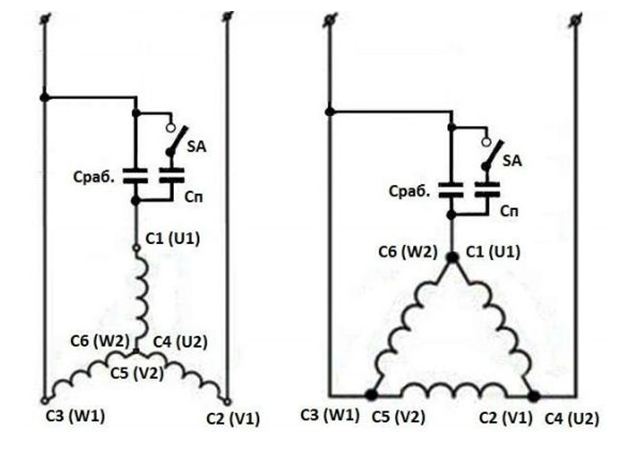
The general startup scheme with a star (left) and a triangle (right) connection will be as follows:
To save on payments for electricity, our readers advise the "Energy Saving Electricity Saving Box". Monthly payments will be 30-50% less than they were before the use of the economist. It removes the reactive component from the network, as a result of which the load decreases and, as a consequence, the consumption current. Electric appliances consume less electricity, and lower the cost of paying for it.
As can be seen, in the first and in the second case, two of the three windings are connected directly to the single-phase network on 220V. The third phase is looped to one of the two previous ones by means of an intermediate chain of capacitors: C slave - main / working and C n - for start-up. The second is connected in parallel through the SA key. The latter has normally open contacts, and the extreme position of the button is not fixed - in order for the current to flow through the starting capacitor, it must be kept pressed.
Why are parallel capacitors used?
 Anyone who at one time was not yawning at physics lessons should remember that the maximum energy consumption by a three-phase motor is observed exactly at the moment of its start, when there is an increase in the speed of rotation from 0 to nominal. The more power, the higher the peak consumption of electricity. From which follows the logical conclusion - the capacity that will support the work on the 220V is likely not enough to start. Therefore, for the output of the motor to the mode of its calculation, it is necessary to increase approximately twice that of the working one.
After starting, when the optimum speed (not less than 70% of the rated speed) is reached, the starting capacitors are switched off by releasing the SA button. It is necessary to do this, otherwise a large total capacitance will cause a serious phase skew and overheating of the windings.
If the power of the motor is small or it does not work under a serious load, then most likely it will be possible to manage the start through the working circuit.
How to calculate the capacitance and choose a capacitor
Obviously, the issue of choosing capacities for starting and operating a three-phase motor in a single-phase network depends on its power, nominal (phase) current and voltage. The calculation is usually carried out through the following formulas:

In this equation there are two values:
- U - voltage in a single-phase network (220V);
- I H - rated or phase current, A.
Both wiring diagrams give different values for the linear and phase characteristics, as can be seen in the following illustrations:
![]()
Calculate the required current between the windings can be using ticks or using formulas. If both are difficult to compute, you can calculate and select a capacitor through an empirical relationship: 7 μF per 100 watts of power.
As for the starting capacitors, their selection is carried out with the expectation that the capacity should be higher than that of the workers in order to cover the peak consumption at start-up. Different sources indicate different values of the proportional coefficient: from 1.5 to 3. In practice, the recommendation for a two-fold increase is most often used.
Next, you can select the capacitors and proceed to the layout. To start the engine, paper (MBGP, KBP, MBGO), electrolytic or metallized polypropylene (SVB) models are used. The first, as a rule, massive and cheap, but have a relatively large size with a small capacity, which forces the accumulation of entire batteries. Electrolytic models require the use of diode elements and resistance in the control circuit, the damage or failure of which will lead to the destruction of the capacitor. UHV models are more modern, and therefore they do not have practically the disadvantages that are present in analogues. According to the form, capacitive blocks can be produced either square or round (kegs).
Also, the operating voltage of the capacitor should be selected, which by calculation should be approximately 1.15 times higher than in a single-phase 220V network. Smaller values have a negative effect on the longevity of the blocks, and larger ones on the dimensions of the assembly.
Content:Quite often there is a need for a non-standard connection of an electrical appliance, in relation to specific conditions. Among the possible options should be allocated connection of a three-phase motor to a single-phase network, widely used in domestic conditions. This scheme fully justifies itself, despite some decrease in the power of the connected equipment.
Connecting a three-phase motor to a single-phase network via a capacitor
Connecting a three-phase motor to a network with a voltage of 220 volts is quite simple. In a standard situation, each phase has its own sine wave. Between them there is a phase shift of 120 degrees. Due to this, a smooth rotation in the stator of the electromagnetic field is ensured.
Each wave has an amplitude of 220 volts, which makes it possible to connect a three-phase motor to a normal network. The acquisition of three sinusoids from one phase occurs by means of a conventional capacitor, provided. Combined in a single ring, they allow you to get a phase shift of 45 and 90 degrees, which is sufficient for not too active operation of the shaft.
The use of a capacitor makes it possible to achieve an engine power in one phase of approximately 50-60% of the same index for three phases. However, this scheme does not apply to all electric motors, so you should choose the most suitable model, for example, APS, AO, A, AO2 and others.
One of the conditions for using a capacitor is the need to change its capacity in accordance with the number of revolutions. Practical implementation of this condition is a serious problem, therefore the engine control is performed in a two-stage version. During the startup, two condensers are connected at once, one of which is disconnected after the acceleration. There remains only a worker who continues to function.

How to choose a capacitor for a three-phase motor
The starting capacitor should be approximately 2-2.5 times the capacity of the working capacitor. The design voltage of these devices is usually 1.5 times the mains voltage. For networks of 220 volts, the best option will be condensers MBPG, MBGO, MBGCH, operating voltage of 500 volts or more. If capacitors are switched on only for a short time, electrolytic devices such as KE-2, K50-3, EGTS-M with a minimum voltage of 450 volts can be used in the circuit.
Between themselves, the capacitors are connected in series, through negative terminals. Next, a resistor is added to the circuit, with a resistance of 200-300 ohms, which cleans the remaining electric charge with capacitors.
Calculation of the capacitor for a three-phase motor
Normal work three-phase electric motor with start-up through a capacitor depends on a number of conditions. One is to change the capacity of the device in accordance with the engine speed. This is achieved through a two-stage control, consisting of two capacitors - starting and working.

During the start, the contacts close, then the acceleration button is pressed. After enough speed has been dialed, the button should be released. The working capacity can be calculated using the following formula: Cp = 4800x I / U, where Cp is the capacitance of the device in μF, I is the current absorbed by the motor in amperes, U is the voltage electrical network in volts. This formula is suitable for connecting windings of an engine using the triangle method. If the motor windings are connected by a star, the formula Cp = 2800x I / U is applied.
Thus, the connection of a three-phase motor to a single-phase network has its own characteristics. For example, the capacitance of the starting and operating capacitor must correspond to the power of the connected motor.
The method of starting a three-phase asynchronous electric motor using phase-shift capacitors is the simplest in the implementation; to start the engine it is supposed to connect the capacitor to its two stator windings. Details about the capacitor start can be read in the article.
Calculator for starting and working capacitors
For a better performance of the three-phase motor when starting it in a single-phase network, it is advisable to use two capacitor tanks; one only for starting ("acceleration" of the engine - until reaching the nominal speed), the second one for operation (permanently connected to two stator windings).
The capacitance required to start and operate a three-phase motor in a single-phase network depends directly on the power and. So, for start-up of the electric motor with the windings connected under the "triangle" scheme, a much larger capacity will be required than for starting when they are connected by a "star".
The starting and working capacities calculated by the proposed calculator can be recruited either by one or several parallel capacitors. In cases of frequent operation of the electric motor in idle or underload mode it will be expedient to reduce the capacity of the starting capacitor.
The use of actual instead of the preset voltage values offered in the calculator, efficiency and power factor of the engine will allow obtaining more accurate results of the capacity required for starting and running the electric motor.
Bookmark this site
To disable the starting capacitor, you can use an additional relay K1, then the need for the toggle switch SA1 disappears, and the capacitor will be shut off automatically (Fig. 5).

By pressing the button SB1, the relay K1 is activated and the contact pair K1.1 switches on the magnetic starter KM1, and K1.2 - the starting capacitor С п. The magnetic starter KM1 is self-blocked by means of its contact pair KM 1.1, and the contacts KM 1.2 and KM 1.3 connect the motor to the network.
The "Start" button is kept pressed until the engine is fully accelerated, and then released. Relay K1 is de-energized and disconnects the starting capacitor, which is discharged through resistor R2. At the same time, the magnetic starter KM 1 remains on and provides power to the motor in the operating mode.
To stop the motor, press the "Stop" button. In the improved starting device according to the scheme in Fig. 5, it is possible to use a relay of the MKU-48 type or the like.
Use of electrolytic capacitors in motor startup circuits
When three-phase asynchronous electric motors As a rule, conventional paper capacitors are used in a single-phase network. Practice has shown that instead of cumbersome paper capacitors, one can use oxide (electrolytic) capacitors, which are smaller and more accessible in terms of purchase.

The replacement scheme for a conventional paper condenser is shown in Fig. 6.
Positive half-wave alternating current passes through the chain VD1, C2, and the negative VD2, C2. Proceeding from this, it is possible to use oxide capacitors with an allowable voltage two times lower than for conventional capacitors of the same capacitance.
For example, if a paper capacitor of 400 V is used in a circuit for a 220 V single-phase network, then an electrolytic capacitor of 200 V can be used when replacing it with the above circuit. In the above diagram, the capacitances of both capacitors are the same and are chosen in the same way as the paper capacitor selection method starting device.
The inclusion of a three-phase motor in a single-phase network using electrolytic capacitors
The scheme of switching the three-phase motor into a single-phase network using electrolytic capacitors is shown in Fig.
In the above diagram, SA1 is the motor rotation direction switch, SB1 is the engine acceleration button, electrolytic capacitors C1 and C3 are used to start the engine, C2 and C4 are in operation.
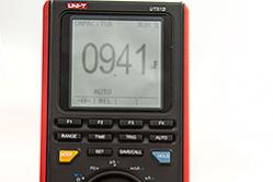
Selection of electrolytic capacitors in the circuit of Fig. 7 it is better to produce with the help of current clamps. Measure the currents at points A, B, C and achieve equalities in the currents at these points by stepwise selection of capacitor capacitances. Measurements are carried out with the engine loaded in the mode in which it is expected to operate.

The diodes VD1 and VD2 for the 220 V network are selected with a reverse maximum permissible voltage of at least 300 V. The maximum forward current of the diode depends on the engine power. For electric motors up to 1 kW the diodes D245, D245A, D246, D246A, D247 with direct current 10A are suitable.
With a larger engine power from 1 kW to 2 kW, you need to take more powerful diodes with the appropriate direct current or put a bit less high-power diodes in parallel, by installing them on the radiators.
Attention should be paid to that when the diode is overloaded, its breakdown can occur and an alternating current will flow through the electrolytic capacitor, which can lead to its heating and explosion.
The inclusion of powerful three-phase motors in a single-phase network
The capacitor circuit of the inclusion of three-phase motors in a single-phase network allows to obtain from the engine no more than 60% of the rated power, while the power limit of the electrified device is limited to 1.2 kW. This is clearly not enough for the work of an electric gun or electric saws, which must have a power of 1.5 ... 2 kW. The problem in this case can be solved by using a larger electric motor, for example 3 ... 4 kW. This type of motors are rated at 380 V, their windings are connected by a "star", and the terminal box contains only 3 pins.
The inclusion of such an engine in a 220 V network leads to a reduction in the rated power of the engine by a factor of 3 and by 40% when operating in a single-phase network. Such a reduction in power makes the engine unsuitable for operation, but can be used to spin the rotor idle or with minimal load. Practice shows that most of the electric motors are confidently accelerated to nominal speeds, and in this case starting currents do not exceed 20 A.
Finalization of three-phase motor
The most simple way is to convert a powerful three-phase motor into an operating mode, if you convert it to a single-phase operation mode, while receiving 50% of the rated output. Switching the motor to single-phase operation requires a small improvement.

Open the terminal box and determine which side of the motor housing cover the terminals of the windings are suitable for. Unscrew the cover fixing bolts and remove it from the engine housing. Find the place of connection of three windings to a common point and solder to a common point an additional conductor with a section corresponding to the section of the winding wire. The twist with the soldered conductor is insulated with an insulating tape or a PVC tube, and the additional lead is pulled into the terminal box. After that, the cover of the casing is put in place.
The circuit of commutation of the electric motor in this case will have the form shown in Fig. 8.
During the acceleration of the engine, the winding is connected with a "star" with the connection of the phase-shifting capacitor Cn. In the operating mode, only one winding remains in the network, and the rotation of the rotor is maintained by the pulsating magnetic field. After switching the windings, the capacitor Cn is discharged through the resistor Rp. The work of the presented circuit was tested with an AIR-100S2Y3 (4 kW, 2800 rpm) engine mounted on a self-made woodworking machine and proved effective.
Details
In the switching circuit of the motor windings, as a switching device SA1, a batch switch for operating current not less than 16 A, for example a switch type PP2-25 / H3 (bipolar with a neutral, for 25 A) should be used. The switch SA2 can be of any type, but at a current of at least 16 A. If the reverse is not required, then this switch SA2 can be excluded from the circuit.
The disadvantage of the proposed scheme for incorporating a powerful three-phase electric motor into a single-phase network can be considered as the sensitivity of the engine to overloads. If the load on the shaft reaches half the engine power, then the speed of rotation of the shaft may decrease, until it stops completely. In this case, the load is removed from the motor shaft. The switch is first moved to the "Overclocking" position, and then to the "Work" position, after which they continue their further work.
In order to improve the starting characteristics of the engines, in addition to starting and operating capacitors, inductance can also be used, which improves the uniformity of phase loading.
The function of the stabilizers is that they act as capacitive energy fillers for the stabilizer filter rectifiers. They can also transmit signals between amplifiers. To start and run for an extended amount of time, in an alternating current system for asynchronous motors also use capacitors. The operating time of such a system can be varied by using the capacitance of the selected capacitor.
The first and only main parameter of the above tool is capacity. It depends on the area of the active connection, which is insulated with a dielectric layer. This layer is almost invisible to the human eye, a small number of atomic layers form the width of the film.
Electrolyte is used in the event that it is necessary to restore the oxide film layer. For the correct operation of the device, it is necessary that the system is connected to a network with alternating current of 220 V and has a well-defined polarity.
That is, a capacitor is created in order to accumulate, store and transmit a certain amount of energy. So why they are needed, if you can connect the power source directly to the engine. Everything is not so simple. If you connect the motor directly to the power source, at best it will not work, at worst it will burn.
In order for the three-phase motor to work in single-phase circuit You need an apparatus that can shift the phase by 90 ° on the working (third) terminal. Also, the capacitor plays a role, such an inductor, due to the fact that an alternating current passes through it - its jumps are leveled by the fact that, before work, in a condenser negative and positive charges are uniformly accumulated on the plates and then transmitted to the receiving device.
There are 3 main types of capacitors:
- Electrolytic;
- Non-polar;
- The polar.
Description of varieties of capacitors and calculation of specific capacitance

Selecting the best option Several factors need to be considered. If the connection is via a single-phase network with a voltage of 220 V, then a phase-shift mechanism must be used for starting. Moreover, there should be two, not only for the condenser itself, but also for the engine. The formulas by which the specific capacity of the capacitor is calculated depends on the type of connection to the system, there are only two of them: a triangle and a star.
I 1 - rated current of the motor phase, A (Amps, most often indicated on the engine package);
U network - voltage in the network (the most standard versions are 220 and 380 V). There is more tension, but they require completely different types of connection and more powerful engines.
Cn = Cp + Co
where Сп - Starting capacity, Ср - working capacity, Co - disconnected capacity.
So as not to strain the calculations, intelligent people have derived average, optimal values, knowing the optimum power of electric motors, which is indicated by M. An important rule is that the starting capacity must be greater than the working capacity.
With a power of 0.4 to 0.8 kW: a working capacity of 40 μF, a starting power of 80 μF, 0.8 to 1.1 kW: 80 μF and 160 μF, respectively. From 1.1 to 1.5 kW: Cp - 100 μF, Cn - 200 μF. From 1.5-2.2 kW: Cp - 150 μF, Cn 250 μF; At 2.2 kW, the working power must be at least 230 μF, and the starting power must be at 300 μF.
When connecting an engine designed to operate at 380 V, an AC mains with a voltage of 220 V, there is a loss of half the rated power, although this has no effect, but the rotor speed. When calculating the power this is an important factor, it is possible to reduce these losses with the "triangle" connection scheme, in this case the efficiency of the engine will be 70%.

It is better not to use polar capacitors in a system of ac connected to the network, in this case the dielectric layer breaks down and the apparatus heats up and, as a result, short-circuiting
Connection scheme "Triangle"
The connection itself is relatively easy, connecting the conductor to and to the motor (or motor) terminals. That is, if it is simpler to take a motor there are three conductive in it. 1 - zero, 2 - working, 3-phase.
The power lead is illuminated and there are two main wires in the blue and brown windings, brown is connected to 1 terminal, one of the condenser wires is attached to it, the second working wire is connected to the second working terminal, and the blue power wire is connected to the phase.
If the motor power is small, up to one and a half kW, in principle only one capacitor can be used. But when working with loads and with large capacities, the mandatory use of two capacitors, they are connected among themselves in series, but there is a trigger mechanism between them, popularly called "thermal", which turns off the capacitor when the required volume is reached.
A small reminder that a capacitor with a lower power, starting, will be switched on for a short time to increase the starting torque. By the way, it's fashionable to use a mechanical switch, which the user himself will turn on for a specified time.
It is necessary to understand that the winding of the motor itself already has a connection according to the "star" scheme, but it is converted into a "triangle" by means of wires. Here the main thing is to distribute the wires that enter the junction box.

Connection scheme "Triangle" and "Star"
Connection scheme "Star"
But if the engine has 6 outputs - terminals for connection, then it should be untwisted and see which terminals are interconnected among themselves. After that, she re-connects all in the same triangle.
To do this, change the jumpers, for example, on the engine there are 2 rows of terminals for 3 pieces, they are numbered from left to right (123.456), with wires connected in series 1 to 4, 2 to 5, 3 to 6, you first need to find regulatory documents and see on which relay is the start and end of the winding.
In this case, the conditional 456 will become: zero, working and phase, respectively. A capacitor is connected to them, as in the previous scheme.
When the capacitors are connected it remains only to test the assembled circuit, the main thing is not to get confused in the wire connection sequence.