Antipyretics for children are prescribed by a pediatrician. But there are situations of emergency care for fever, when the child needs to give the medicine immediately. Then the parents take responsibility and apply antipyretic drugs. What is allowed to give to infants? How can you bring down the temperature in older children? Which medications are the safest?
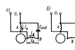
The asynchronous condenser motor has two windings on the stator, occupying the same number of grooves and displaced in space relative to each other by 90 e. deg. One of the windings - the main one - is directly connected to the single-phase network, and the other - to the auxiliary one - is connected to the same network, but through the working capacitor C pa6 (Figure 16.7, a).
In contrast to the previously considered single-phase asynchronous motor in a capacitor motor, the auxiliary winding after start-up is not switched off and remains on for the entire operation period, while capacitance C creates a phase shift between the currents and.
Thus, if a single-phase asynchronous motor, upon termination of the start-up process, operates with a pulsating MDS of the stator, then the condenser motor - with a rotating one. Therefore, the capacitor motors are close in their properties to the three-phase motors.
The capacity (μF) required to obtain a circular rotating field
C slave = 1.6 10 5 I A sin φ A / (f 1 U A k 2),(16.4)
the ratio of the voltages on the main U A and on the auxiliary U B windings must be
U A / U B = tan φ A ≠ 1.
Hereφ A is the angle of phase shift between current and voltage in a circular field; k = ω B k B / ( w A k A ) - coefficient of transformation, representing the ratio

Fig. 16.7. Condenser motor:
a - with a working capacity, b - with a working and starting capacities, in - mechanical characteristics; 1- at the working capacity, 2 at the working and starting capacities
effective numbers of turns of auxiliary and main windings; k A and k B are the winding coefficients of the stator windings.
Analysis (16.4) shows that, given the transformation coefficient k and the voltage ratio U A / U B, the capacitance C pa6 ensures that a circular rotating field is obtained only with a single, completely defined operating mode of the engine. If the mode (load) changes, both the current I A and the phase angle φ A, and, consequently, the C slave corresponding to the circular field also change. Thus, if the load of the engine is different from the calculated one, the rotating field of the motor becomes elliptical and the working properties of the engine deteriorate. Usually the calculation of C slave is for a nominal load or close to it.
Possessing relatively high efficiency and power factor (cos φ 1 = 0,80 ÷ 0,95), the capacitor motors have unsatisfactory starting properties, since the capacitance C provides a circular field only at the design load, and when the engine is started, the stator field is elliptical. In this case, the starting torque usually does not exceed 0.5 M HOM.
To increase the starting torque parallel to the capacitance C the slave includes a capacitor C starting, called the starting (Figure 16.7, b) . The value of C starting is selected based on the condition for obtaining a circular stator field at engine start-up, i.e., obtaining the greatest starting torque. At the end of the start-up, the C start-up should be switched off, since for small slip in the stator winding circuit containing the capacitance C, the inductance L , a resonance of the voltage is possible, because of which the voltage on the winding and on the capacitor can be two to three times higher than the voltage of the network.
When choosing the type of capacitor, remember that its operating voltage is determined by the amplitude value of the sinusoidal voltage applied to the capacitor U c. With a rotating rotating field, this voltage (B) exceeds the voltage of the network U 1 and is given by
U c = U 1  (16.5)

Fig. 16.8. Schemes for switching a two-phase motor into a three-phase network
Condenser motors are sometimes called two-phase , since the stator winding of this motor contains two phases. Two-phase motors can operate without either a capacitor or other FE, if a two-phase system of voltages is applied to the phases of the stator winding (two voltages that are the same in value and frequency, but shifted 90 ° relative to each other). To obtain a two-phase system of voltages, you can use a three-phase line with zero conductor, including the stator windings as shown in Fig. 16.8, a : one winding - the line voltage U AB, and the other - the phase voltage Uc through the autotransformer AT (to equalize the voltage values in the phase windings of the motor). It is possible to start the engine without a neutral wire (Fig. 16.8, b ), but in this case the voltages on the motor windings will be shifted in phase by 120 °, which will lead to a certain deterioration in the working properties of the engine.
There are different wiring schemes, more options for three-phase motors, differing in the way of connecting the engine windings and the composition of additional elements, but the minimal efficient circuit contains one capacitor, from which the name comes.
Typically, one of the windings (the "motor phase") is fed directly from the single-phase network, and the other windings are fed through electric condenser , which shifts the phase of the applied current by almost + 90 °, or through coil , which shifts the phase by almost -90 °. To the resultant rotating magnetic field was not elliptical, consistently with a capacitor, an alternating wire resistor , by means of which a circular rotating magnetic field is achieved.
Application
Industrial capacitor motors are based, as a rule, a two-phase motor (simpler production and wiring diagram). Three-phase motors are converted to a single-phase network usually in a private or small-scale production due to the mass nature of these types of motors and networks, while choosing between the complexity of the circuit and the underutilization of engine power.
Such engines are used mainly in low-power household appliances: activator washing machines, coil and stationary cassette tape recorders, inexpensive turntable players, fans and other similar equipment.
Also such engines are used in circulating pumps of water and heating systems (eg companies Grundfos), and in blowers and smoke exhausters of heating and water-heating units (eg. Buderus).
Three-phase asynchronous motors in a single-phase electrical network are connected via a phase-shifting capacitor.
The output of one winding of the motor is connected to the "phase" wire, the output of the second winding - to neutral wire . The output of the third winding is connected through a capacitor, the capacitance of which is selected according to the formulas, depending on how the windings of the motor are connected - "Star" or "triangle".
If the windings are connected by a "star", then the capacitance of the "working" capacitor must be
C R A B. Z V E Z D A = 2800 I U (\\ displaystyle C_ (RAB.ZVEZDA) = 2800 (\\ frac (I) (U))).
If the windings are connected by a "triangle", then the capacitance of the "working" capacitor must be
C R A B. T R E U G O L N I K = 4800 I U (\\ displaystyle C_ (RAB.TREUGOLNIK) = 4800 (\\ frac (I) (U))), where
U (\\ displaystyle U) - voltage network, volt ;
I (\\ displaystyle I) - operating current engine, ampere ;
C (\\ displaystyle C) - electrical capacitance , microfarade.
When starting the engine, the start capacitor C P U S K (\\ displaystyle C_ (PUSK)), the capacity of which should be twice the capacity of the worker. As soon as the engine has reached the required speed, the "Start" button is released.
Switch B 2 (\\ displaystyle B_ (2)) allows you to change the direction of rotation of the motor. Switch B 1 (\\ displaystyle B_ (1)) disconnects the motor.
Using the motor's passport data, you can determine its operating current I (\\ displaystyle I) according to the formula:
I = P 1, 73 U η cos φ (\\ displaystyle I = (\\ frac (P) (1 (,) 73 ~ U ~ \\ eta ~ \\ cos \\ varphi))), where
Asynchronous motors have been widely used because they are low-noise and easy to operate. Especially this applies to three-phase short-circuited asynchronous machines with their sturdy construction and unpretentiousness.
The main condition for converting electrical energy into mechanical energy is the fact of the existence of a rotating magnetic field. To form such a field, a three-phase network is required, while the electrical windings must be offset by 120 °. Thanks to the rotating field the system will start working. However, household appliances, as a rule, are used in houses with only a single-phase 220 V network.
First, let's define the terminology. Condenser (Latin condensatio - "accumulation") is an electronic component storing an electric charge and consisting of two closely spaced conductors (usually plates) separated by a dielectric material. Plates accumulate electric charge from a power source. One of them accumulates a positive charge, and the other - a negative charge.

Capacity is the amount of electrical charge that is stored in the electrolyte at a voltage of 1 volt. The capacity is measured in Farad (F) units.
Method of connecting the motor through a capacitor - this method is used to achieve a soft start-up of the unit. On the stator of a single-phase engine with a squirrel-cage rotor, one more is placed in addition to the main electrical winding. The two windings are correlated to each other by an angle of 90 °. One of them is working, its purpose is to make the motor work from the 220 V network, the other is an auxiliary one, it is necessary to start.
Consider the connection diagram of capacitors:
- with a switch,
- directly, without a switch;
- parallel inclusion of two electrolytes.
1 option
A phase-shift capacitor is connected to the asynchronous winding. The connection is made to a single-phase 220 V network according to a special scheme.

It can be seen that the electrical winding is directly connected to the 220 V power line, the auxiliary is connected in series with the capacitor and the switch. The latter is designed to disconnect the additional winding from the power supply after starting.
The switching device is configured to remain closed and maintain the auxiliary winding in operation until the motor is started and accelerated to approximately 80% of the full load. At this speed, the breaker opens, disconnecting the auxiliary winding from the power supply. Then the motor operates as an asynchronous motor on the main winding.
Option 2
The circuit is identical to the capacitor motor, but without a switch. The starting torque is only 20-30% of the full torque load.

The use of this type of single-phase motors is generally limited to the direct drive of loads such as fans, blowers or pumps that do not require a high starting torque. Various modifications of the circuits are possible with a preliminary calculation of the capacitor's required capacitance for connection to the 220 V motor.
It should be noted that the provision of better performance is necessary when changing the load of the motor. Increasing the capacitance leads to a decrease in the resistance in the AC circuit. True replacement of the electrolyte capacity somewhat complicates the scheme.
3 option
The connection scheme for the two electrolytes connected in parallel to the motor is shown below. With parallel connection, the total capacity is equal to the sum of the capacities of all connected electrolytes.

C s is the starting capacitor. The value of the capacitive reactance X is the smaller, the greater the capacity of the electrolyte. It is calculated by the formula:
x c = 1 / 2nfC s.
In this case, it should be borne in mind that for 1 kW there is 0.8 μF of working capacity, and for the starting capacity it will be needed 2.5 times more. Before connecting to the engine, it is necessary to "drive" the capacitor through the multimeter. When picking up the parts, remember that the starting capacitor should be 380V.
To control the starting currents (control and limitation of their magnitude) a frequency converter is used. This connection scheme ensures a quiet and smooth running of the motor. The principle of operation is used in pumping equipment, refrigeration units, air compressors, etc. Machines of this type have a higher efficiency and productivity than their analogues, operating only on the main electrical winding.
Methods of connection of a three-phase electric motor
Attempting to adapt some equipment meets certain difficulties, since three-phase asynchronous devices should mostly connect to 380 V. And in the house everyone has a 220 V network. But to connect a three-phase engine to a single-phase network is quite an achievable task.
- Switching on three-phase asynchronous motor.

- Connections of three-phase engine to 220 V, with reverse and control button.

- Connection of three-phase motor windings and starting as single-phase.

- Other possible ways of connecting three-phase electric motors.

Conclusion
Asynchronous motors at 220 V are widely used in everyday life. Proceeding from the required task, there are various methods for connecting a single-phase and three-phase motor through a capacitor: to provide a smooth start or improve performance. You can always easily achieve the desired effect.
50. Condenser induction motors.
The condenser is called an asynchronous electric motor, which is powered from a single-phase network, has two windings on the stator: the first is powered directly from the network, and the second is connected in series with the electric capacitor to create a rotating magnetic field. Condensers form a phase shift of the winding currents whose axes are rotated in space.
The maximum value of the rotating torque is reached when the phase of the currents is shifted by 90 °, and precisely at the moment when their amplitudes are selected so that the rotating field is circular. During start-up of capacitor asynchronous motors, both capacitors are connected, but immediately after acceleration one of them must be switched off. This is because the nominal speed requires a much smaller capacity than the start-up. Condenser asynchronous electric motor in its starting and operating parameters is very similar to a three-phase asynchronous motor. It is used in electric drives of low power; if more than 1 kW is needed, such an electric motor should not be used because of the high cost and size of the capacitors.
An asynchronous electric motor fed from a single-phase network and having two windings on the stator, one of which is connected directly to the network, and the other is connected in series with an electric capacitor to form a rotating magnetic field. Condensers create a phase shift between the currents of the windings whose axes are shifted in space. The greatest torque develops when the phase shift of the currents is 90 °, and their amplitudes are chosen so that the rotating field becomes circular. When starting K. a. Both capacitors are turned on, and after it is accelerated, one of the capacitors is turned off; this is due to the fact that at a nominal rotational speed, a much smaller capacity is required than at start-up. K. a. e.
on starting and operating characteristics is close to a three-phase asynchronous motor.
It is used in electric drives of low power; at capacities over 1 kW is rarely used due to the considerable cost and size of the capacitors.
Three-phase asynchronous electric motor, connected through a capacitor to a single-phase network.
The capacitor's working capacitance for a 3-phase motor is determined by the formula Cp = 2800 1 / U mf if the windings are star-connected, or Cp = 48001 / U (μf) if the windings are connected in a "triangle" pattern. Capacitor capacitance Cn = (2.5 - 3) Avg. The operating voltage of the capacitors should be 1.5 times higher than the mains voltage; capacitors are installed necessarily paper.
51. Asynchronous Actuating Motors
These motors are used in automation devices, they serve to convert the electrical signal supplied to them into the mechanical movement of the shaft. The actuators are motor driven. At a given moment of loading, the engine speed must strictly correspond to the applied voltage and change with changing its magnitude and phase. As executive motors, mainly two-phase asynchronous motors with a squirrel-cage rotor are used (Fig. 2.19a).
Fig. 2.19. Schematic diagram of an induction motor (a)
and vector diagrams of its stresses with amplitude (b) and phase (in) control methods.
One of the stator windings B, called the excitation winding, is connected to an alternating current network with a constant effective voltage value. To the second stator winding Have, called the control winding, connects the control voltage, from the control device UU.
There are three main ways of changing the voltage on the control winding: amplitude, phase and amplitude-phase.
For amplitude control, only the magnitude of the control voltage amplitude or the proportional effective value of this voltage varies (Fig. 2.19b). The magnitude of the control voltage can be estimated by the signal coefficient.
Vectors of control and excitation voltages form an angle for all values of the coefficient. Phase control is characterized by the fact that the control voltage remains unchanged in magnitude, and the speed control is achieved by changing the phase angle between the control and excitation vectors (Fig. 2.19c). As the signal coefficient for phase control, a value equal to the sine of the phase angle between the control and excitation voltage vectors is assumed, i.e..
With amplitude-phase control, both the amplitude of the control voltage and the angle of phase shift between the voltages applied to the stator windings change. This method is carried out practically by including a capacitor in the circuit of the excitation winding, so the amplitude-phase control circuit is often called the capacitor.
With all control methods, the speed of an asynchronous motor changes due to the creation of an asymmetric elliptical magnetic field.