Antipyretics for children are prescribed by a pediatrician. But there are situations of emergency care for fever, when the child needs to give the medicine immediately. Then the parents take responsibility and apply antipyretic drugs. What is allowed to give to infants? How can you bring down the temperature in older children? Which medications are the safest?
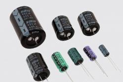
Modern electrolytic capacitors, more correctly called Aluminum electrolytic capacitors, are used in huge quantities in modern electronics. They are cost-effective and can provide a large capacity per unit volume, compared to other types of capacitors. This allows them to be used in circuits where large currents or low frequencies are involved. Aluminum electrolytic capacitors are generally used in such areas as audio amplifiers of all types (from Hi-Fi to mobile phones) and in power circuits. As with any other type of capacitor, one must understand their advantages and limitations, which will allow you use them most effectively.
Development of electrolytic capacitors
Electrolytic capacitor has been used for many years. His story can be traced back to those days when the first voice broadcasts were made. At that time, wireless tube devices were very expensive, besides, these devices had to work on batteries. However, with the further development of vacuum lamps, it became possible to use an alternating current network. It was a great time to power the lamps from the AC mains, rectification and filtering of the anode supply voltage was required, to prevent the network noise that flowed from the power supply to the audio signal. In order to be able to use a capacitor in a radio receiver, it should not be too large, and Julius Lilenfield, who was actively involved in the development of wireless home appliances, was able to make an electrolytic capacitor that allows to have a sufficiently high capacity, at a reasonable size, which in the future and used in radio devices.
Symbols for electrolytic capacitors
The electrolytic capacitor is a form of a polarized capacitor. The symbol of the electrolytic channel has a polarity, and this is important in order to ensure the correct installation of the capacitor and avoid connection in reverse polarity.
Symbols used for polar electrolytic capacitors
There are many schematic symbols used for electrolytic capacitors. The first "1" is the version that is usually used in European schemes, while "2" is used in many American schemes and "3" can be seen on some old schemes. Some schemes do not print a "+" sign next to the plate symbol, where it is already obvious which plate has what polarity.
Production technology of electrolytic capacitor
As the name indicates, the electrolytic capacitor uses an electrolyte (ionic conductive liquid) as one of its plates to achieve a larger capacity per unit volume than other types of capacitors. The capacity of capacitors can be increased in several ways: by increasing the dielectric constant; an increase in the surface area of the electrode; and a decrease in the distance between the electrodes. Electrolytic capacitors use a high dielectric constant of the alumina layer on the capacitor plate, which is on average 7 to 8. This is larger than other dielectrics, such as mylar, which has a dielectric constant of 3 and mica is about 6 to 8. In addition, the effective surface area of the capacitor electrode increases with a roughness factor of up to 120 units for aluminum foil of high purity. This is one of the keys to the production of capacitors with very high capacity.
Construction of electrolytic capacitors
The electrolytic capacitor plates are made of a conductive layer of aluminum foil. This plate is made very thin and flexible, such electrodes are easy to pack into a small volume at the end of the production process.
Both foil electrodes are slightly different. They are covered with an insulating oxide layer, and an insulating paper layer moistened in the electrolyte is laid between them. A foil that is insulated with a thicker oxide layer and is an anode with respect to the liquid electrolyte. The thickness of the thin anodic oxide film is chosen for reasons of working voltage requirements. A foil that goes as a cathode, although it has a natural oxide layer, but it is much thinner.
Structure of the electrolytic capacitor
In order to pack both of the foil liners with electrolyte-impregnated paper, they roll together to form a cylinder and are placed in an aluminum cup. Thus, the electrolytic capacitor is compact and reliable while it is protected by an aluminum cup. There are two geometric shapes that are used to connect the pins. One of them is the use of axial leads, one with each flat surface of the cylinder. Another alternative is to use two leads, both of which are on the same face of the cylinder. The description of the axial and radial leads will be given in the references to the components.
To manufacture an electrolytic capacitor, it is necessary to use foil for an anode of high purity. Typically 50 and 100 microns thick. The cathode is also made of pure aluminum, but the requirements for it are not as stringent as for the anode. The thickness of the foil used is 20 to 50 μm. To increase the surface area of the anode and the cathode, and accordingly, to increase the capacity, the surface roughness is increased by etching. There are two main ways, and both are related to the use of hydrochloric acid.
Properties of electrolytic capacitors
Electrolytic capacitors have a number of parameters that are no less important than capacitance and capacitive resistance. When designing circuits using electrolytic capacitors, you need to pay attention to these parameters, some designs can be very critical to them.
Polarity
Unlike many other types of capacitors, electrolytic capacitors are polar and must be connected accordingly. The capacitors themselves are marked so that the polarity can be easily distinguished. In addition to this, the labeled output is generic.
This is necessary to ensure that any electrolytic capacitors are connected to the circuit in accordance with the polarity. The reverse bias causes an electrochemical reduction of the oxide layer of the dielectric and it turns into a conductor. If this happens, then inevitably leads to a short circuit, and excessive current usually leads to overheating of the capacitor. In this case, the electrolyte may leak, and in some cases the condenser may even explode. Such cases are not uncommon, and precautions should be taken to ensure proper installation, especially in circuits that operate with high currents.
Capacities of electrolytic capacitors and their expected lifetime
First of all, care must be taken not to exceed the rated operating voltage of the electrolytic capacitor. If this rule is not observed, the capacitor will have a considerably shorter service life than declared by the manufacturer. In addition, significant current overloads are possible in the supply circuits. Accordingly, for electrolytic capacitors designed for operation in such circuits, the maximum capacitor current must be taken into account, which also can not be exceeded. If you do not take into account this, the electronic component can overheat and collapse. It is also worth noting that these radio cells have a limited lifespan. And the operating time of all can be only 1000 hours at the maximum value of voltage, but the service life can be significantly extended if the component operates at a voltage well below the maximum permissible voltage.
SMD electrolytic capacitors
Electrolytic capacitors, which are now increasingly used in SMD performance. High capacity combined with their low cost make them especially popular in many areas. Initially, they were not very popular due to the fact that they did not tolerate the ration. The modern improved design of capacitors, along with new soldering methods, the rejection of wave soldering, allows electrolytic capacitors to find wide application in surface mounting.
Often electrolytic SMD capacitors are labeled with a couple of values: capacitance and operating voltage. There are two main ways of marking. The first is the designation of the capacitance value in μF, and the other is the use of a special code. Using the first labeling method "33 6B" will indicate that the capacitor has 33 μF and an operating voltage of 6 volts. The second way of marking has the form of an alphabetic code followed by three digits. The letter indicates the operating voltage, which can be determined from the table below and three digits that indicate capacity in picofarads. As in many other marking systems, the first two digits determine the value, and the third factor. In this case, the marking "G106" will indicate a working voltage of 4 volts and a capacity of 10 * 106 pF or simply 10 μF.
SMD ELECTROLYTIC CAPACITORS
|
|
|---|---|
| LETTER | VOLTAGE |
Marking of electrolytic capacitors
There are many different markings that are used to mark electrolytic capacitors, among which capacity, operating voltage and other parameters. The main values if there is space are recorded directly on the surface, but such moments as accuracy, and sometimes the working voltage can also be encoded. The coding or marking system depends on the type of capacitor, manufacturer, capacity, component size, etc. But this will be in another article. Recovery of aluminum electrolytic capacitors after extended storage It may be necessary to restore electrolytic capacitors that have not been used for six months or more. The electrolytic action tends to dissolve the oxide layer on the anode, and before use it is better to first restore this layer. When thinning the oxide layer, it is reasonable not to use the full voltage, since in the first time there are increased leakage currents, which can lead to the release of a large amount of heat, and this can in some cases lead to its explosion. To restore the capacitor, you can temporarily connect the capacitor to the working voltage through a resistor of about 1.5 kΩ, or slightly smaller for lower-voltage capacitors. (You need to make sure that the resistor has enough power to cope with the capacitor charge current). The recovery lasts for an hour or more until the leakage current falls to an acceptable value, and the voltage across the capacitor reaches the applied value, i.e. current does not flow through the resistor. This voltage is maintained for about an hour. Then the capacitor is slowly discharged through a pull-up resistor so that the stored energy does not damage the circuit in which it will be installed.
The electrolytic capacitor is a capacitor, where the dielectric is a layer of metal oxide on the anode, and the cathode is the electrolyte. As a result, a very large capacity is achieved with a relatively high operating voltage. That determines the high popularity of this kind of products.
History of the origin of electrolytic capacitors
The effect of the electrochemical oxidation of certain metals was discovered by the French scientist Eugène Adrien Ducretet in 1875 using tantalum, niobium, zinc, manganese, titanium, cadmium, antimony, bismuth, aluminum and some other materials as examples. The bottom line was that when the anode (the positive pole of the power supply) was turned on, a layer of oxide with valve properties was growing on the surface. In fact, a kind of Schottky diode is formed, and in some works, aluminum oxide is attributed to n-type conductivity.
This means that the contact point has rectifying properties. Now we can easily assume further, if we recall the qualities of the Schottky barrier. This is primarily a low voltage drop when switched on in the forward direction. But what does low mean? With capacitors this will be a significant amount. As for the reverse inclusion of electrolytic capacitors, many have heard about the danger of such experiments. The fact is that the Schottky barrier has high leakage currents, due to which the oxide layer starts to degrade immediately. But in this case, a considerable role is assigned to tunnel breakdown. The flowing chemical reaction is accompanied by the release of gases, due to which the negative effect occurs. Theorists say that this phenomenon also leads to the release of heat.
The year of the invention of the electrolytic capacitor is called 1896, when on January 14 Carol Pollack submitted his application to the patent office of Frankfurt. So, on the anode of the electrolytic capacitor, the oxide layer builds up under the action of a positive potential. This process is called forming and in the conditions of modern technology development lasts for hours and even days. For the same reason, the growth or degradation of the oxide layer is invisible during operation. Electrolytic capacitors are used in electrical circuits with a frequency of up to 30 kHz, which means the time to change the current direction in tens of microseconds. During this period nothing will happen with the oxide film.
For a while in domestic practice, the industrial production of electrolytic capacitors was not economically viable. Up to the point that scientific journals examined how it is possible to establish the production process. Such articles include the article of Mitkevich (Journal of the Russian Physico-Chemical Society, Physics No. 34 for 1902). The electrolytic capacitor in question consisted of a flat aluminum anode and two iron cathodes located on the sides. The design was placed in a 6-8% solution of baking soda. The molding was carried out with a constant voltage (see below) 100 V up to a residual current of 100 mA.
The first serious achievements of domestic ownership of capacitors with liquid electrolyte belong to 1931 and were created by the laboratory of PA Ostroumov.
The ability of valve metals with oxide film to straighten the current is not the same. Most clearly, these qualities are expressed in tantalum. Apparently, the strength of the fact that tantalum pentoxide has p-type conductivity. As a result, a change in polarity leads to the formation of a Schottky diode switched on in the forward direction. Thanks to the specific selection of the electrolyte, the degrading working layer of the dielectric can be reconstructed. Right in the process of work. On this historical excursion can be completed.
Manufacture of electrolytic capacitors
Metals, whose oxides have rectifying properties, were called gate valves in analogy with semiconductor diodes. It is not difficult to guess that oxidation should lead to the formation of a material with n-type conductivity. This is the main condition for the existence of a valve metal. Of the above-listed, only two have a pronounced positive properties:
- Aluminum.
- Tantalum.

The first is applied many times more often, due to relative cheapness and prevalence in the Earth's crust. Tantalum is used only in extreme cases. The build-up of oxide film can occur in several ways:
- One technique is to maintain a constant current. As the thickness of the oxide grows, its resistance increases. Therefore, in the chain in series with the condenser for the time of molding should include a rheostat. The process is monitored by the voltage drop at the Schottky junction and, if necessary, the shunt is adjusted so that the parameters remain constant. The molding speed is at the initial stage constant, then the inflection point with the decrease of the parameter follows, and after a certain interval the further growth of the oxide film goes so slowly that the technological cycle can be considered to be completed. At the first bend, the anode often begins to spark. Accordingly, the voltage at which this occurs is also called the same. At the second point, arcing sharply increases, and further molding is not practical. And the second inflection is called the maximum stress.
- The second method of forming the oxide layer is to maintain a constant voltage on the anode. In this case, the current will decrease exponentially with time. Voltage is usually selected below the spark voltage. The process goes to some residual forward current, below which the level no longer drops. This completes the molding process.
The proper selection of the electrolyte plays an important role in the shaping process. In industry, this amounts to studying the interaction of corrosive media with aluminum:

For tantalum and niobium, all electrolytes are classified as first group. The capacitance of the capacitor is determined mainly by the voltage at which the molding is completed. Similarly, polyhydric alcohols are used, including glycerol and ethylene glycol, and many salts. Not all processes go strictly according to the scheme described above. Thus, for example, when aluminum is formed in a solution of sulfuric acid by the direct current method, the following sections are isolated on the graph:
- A few seconds there is a fairly rapid increase in voltage.
- Then, at the same rate, a decline to a level of about 70% of the peak reached is observed.
- For the third stage, a thick porous oxide layer builds up, but the voltage grows very slowly.
- In the fourth section, the voltage rises sharply until the onset of a spark breakdown. This completes the molding process.
A lot depends on the technology. The thickness of the layer, and therefore the operating voltage and the durability of the capacitor, affect the electrolyte concentration, temperature, and some other parameters.
Electrolytic capacitor design
These are capacitors with a dry electrolyte. Their key advantage in the good use of volume. Excess electrolyte is practically absent, which reduces weight and dimensions with the same electrical capacity. Despite the characteristic name of the electrolyte is not dry, but rather viscous. They are impregnated with linings made of cloth or paper, located between the plates. Due to the viscosity of the electrolyte, the housing can be plastic or even paper, a resin seal is used for sealing. As a result, the technological cycle of manufacturing products is simplified. Historically, varieties with dry electrolyte appeared later. In the domestic practice, the first mention is in 1934.
At the end of the foreign electrolytic capacitors are usually cross-cut, through which the internal volume is squeezed out. This is in case of an accident. Such a spoiled condenser can easily be noticed with the naked eye and replaced in a timely manner, which speeds up the repair process considerably. The casing marking helps to avoid accident and incorrect polarity of the switch. From the side of the cathode on imported, the white strip with the minuses placed on it is usually drawn along the whole height, and the crosses on the opposite side have crosses (pluses).
To increase the emissivity of the body color is dark. There are exceptions to this rule, but they are rare. Such a measure increases the heat transfer to the environment. When the voltage on the working (molding) voltage is exceeded, a sharp increase in the current occurs due to ionization, strong sparks are observed at the anode, and a layer of dielectric is partially penetrated. The consequences of such phenomena are easily eliminated in the design and with the housing used as a cathode: capacitors with liquid electrolyte occupy a relatively large space, but heat is well removed. But they show themselves well when working at low frequencies. That determines the specificity of their use as filters of power supplies (50 Hz).
These cylindrical electrolytic capacitors are not arranged as shown above, and do not have paper tabs. In some models, the housing plays the role of a cathode, while the anode is inside and can be of arbitrary shape so that the maximum nominal capacity is ensured. Due to mechanical processing and chemical etching, designed to increase the surface area of the electrode, parameters can be raised by an order of magnitude. This design is typical for models with liquid electrolyte. The capacitance of the design in question varies when the industry releases from 5 to 20 μF at an operating voltage of 200 to 550 V. Because of the increase in the resistance of the electrolyte with a decrease in temperature, the capacitors with liquid electrolyte and the casing are used primarily as cathodes in a warm microclimate.
In practical activity, every electrician faces the work of adapters, power supplies, voltage converters. In all these devices, electric capacitors are widely used, which on slang are often called "electrolytes".
Their main advantage is the relatively large size of the capacitance with relatively small dimensions. In addition, their production has long been established, and the cost is relatively low.
Principles of the device
Any capacitor consists of two plates, the space between which is filled with a dielectric.
The formula shown in the picture reminds that the capacitance C depends on the area of each electrode S, the distance between the plates d and the dielectric constant of the medium inside their ε. The quantity ε0 is the electric constant that determines the electric field strength inside the vacuum.
The electrolytic capacitor differs from all the others in that it uses an electrolyte layer that fills the space between two plates, most often made of foil plates. One of them is covered with a small dielectric layer of the oxide film.

Tapes of foil are piled together, separated by a very thin paper pad impregnated with electrolyte. Its value of about 1 μm makes it possible to significantly increase the capacity of the capacitor. In the above definition formula C, the thickness of the dielectric layer d is in the denominator.
The upper layer of the foil is covered with separating paper, and the entire structure is rolled into a roll for placement in a cylindrical body.

At the ends of the foil by cold welding methods, metal plates are welded, providing contacts for connection to the electrical circuit as a cathode and an anode. Moreover, a positive terminal is formed on the plate with the oxide layer.
The role of the cathode is performed by the electrolyte, which contacts the entire surface of the second electrode.
Since the capacitance of a capacitor depends on the area of the plates, one of the ways to increase it is included in the production technology: it is the surface corrugation from the electrolyte side by the methods of chemical etching. It can be carried out due to chemical erosion or electrochemical corrosion.

Liquid electrolytes can safely flow into the created microscopic indentations of the anode.
The oxide layer on the foil is created during electrical oxidation. This process occurs when the current passes through the electrolyte. The picture below shows the current-voltage characteristic, which shows the change of currents inside the device when the voltage is increased.

The capacitor operates normally at the rated voltage and temperature. If there is an overvoltage, the formation of a layer of oxides is resumed and a large amount of heat begins to be released, which leads to gas generation and increased pressure inside the hermetic housing.
Therefore, electrolytic capacitors are capable of exploding, which often occurred with the old designs of the times of the USSR, which were performed by a single hull without creating protection against the explosion. This property often led to damage to other, neighboring equipment elements.
Modern models create a safety membrane, which is destroyed at the beginning of gas generation and thereby prevents an explosion. It is made in the form of notches of letters "T", "Y" or the sign "+".

Types of electrolytic capacitors
By their design, "electrolytes" refer to polar devices, that is, they should work when passing current only one way. Therefore, they are used in circuits of constant or pulsating voltage, taking into account the direction of the passage of electric charges.
To work in sinusoidal current circuits, "non-polar electrolytes" are created. Due to additional elements in the design, they have an equal capacity and have increased dimensions and, accordingly, cost.
Electrolyte between the plates can be used concentrated solutions of various alkalis or acids. By the way they are filled, the capacitors are divided into:
oxide-metal;
oxide semiconductor.
liquid;

As an anode material, aluminum, tantalum, niobium, or sintered powder can be chosen. In oxide-semiconductor capacitors, the cathode is a layer of a semiconductor deposited directly on the oxide layer.
Features of operation
The ability of electrolytes to evolve gases when heated dictates the necessity for the operation of the capacitor to ensure the reliability of creating a reserve at a nominal voltage of up to 0.5 ÷ 0.6 of its magnitude. This is especially true for use in devices with elevated temperatures.
Capacitors designed for operation in alternating voltage circuits are subject to an operating frequency. Usually this is 50 hertz. To work with higher frequency signals, it is necessary to reduce the operating voltage. Otherwise there will be overheating of the dielectric and breakdown, rupture of the case.
Electrolytes with large capacitance and low leakage currents are able to preserve the accumulated charge for a long time. For safety reasons, a resistor with a resistance of 1 MΩ and a power of 0.5 W is connected in parallel to the leads to accelerate their discharge.
For use in high-voltage devices, capacitors are used, assembled by successive chains. In order to equalize the voltage between them, resistors with a nominal value of 0.2 to 1 MΩ are connected in parallel to the terminals of each.
If it is necessary to use polar electrolytic capacitors in alternating voltage circuits, a circuit is assembled in which the current through each element passes only in one direction. To do this, use a current limiting resistor.

Such circuits were previously assembled to turn the phase of the current relative to the voltage at the start of the powerful three-phase asynchronous motors from a single-phase network. Now this issue is already losing its former relevance.
The absence of a current-limiting resistor in such a chain leads to overheating of the dielectric layer and failure of the electrolytic capacitor.
Liquid electrolyte since time dries through the defects of the body. Due to this, the capacity gradually decreases. Over time, it reaches a critical value. The electrolytic capacitor that has come out of working condition most often becomes the cause of the breakdown of the electrical appliance.
Condenser malfunctions due to violation of equivalent resistance ESR
Electrolytic capacitors have one more technical feature that affects its characteristics during operation. With the time of work at the condenser, the electrical conductivity between the plates and terminals is gradually reduced due to the continuous internal electrical processes. Its value is estimated by the equivalent active resistance, which is denoted by the ESR index. In Russian, they call EPS: equivalent series resistance.
The condenser, which has an increased ERS, does not differ in appearance from the serviceable one in appearance. Just its active resistance increases more than one Ohm and can reach up to 10 Ohm.
The methods for determining
The industry produces instruments that allow measuring this value on the basis of the prototype invented in Russia in the 1960s. They allow you to perform measurements without evaporating the capacitors from the circuit, working on the principle of bridge resistance meters for alternating current.
Folk craftsmen create their own simplified designs that allow to evaluate the serviceability of the capacitor in this parameter on the basis of the determination of the active resistance exceeding 1 ohm. As a similar indicator, you can assemble a simple device, shown in the diagram.
![]()
A regular finger battery is used to power it. The LED with its glow indicates the suitability of the electric capacitor for the ERS parameter by comparing high-frequency signals on the toroidal transformer coming from the capacitor and the formed oscillatory circuit.
The image of the same scheme is shown in a somewhat simplified form below.

The test capacitor is connected to a winding made with a single turn on a transformer made of a ferromagnetic core with a magnetic permeability of the order of 800 ÷ 1000. On this winding the voltage does not exceed 200 millivolts, therefore it is possible to evaluate the characteristics of the electrolyte without evacuation from the board.
This indicator does not require special adjustment. It is quite enough to check the glow of the LED on the control resistor in one Ohm and follow it in further measurements. The transistor can be used by anyone with a collector current of 100 mA and a gain of more than 50.
Such a probe will not accurately work with capacitors having a capacitance of less than 100 μF.
Ionistor - supercapacitor
A kind of condenser with an electrolyte, which provides the flow of electrochemical processes, is. It uses the effect of a double electrical layer that occurs when the electrode material contacts the electrolyte and combines the functions of the capacitor with a chemical source of current.
Its construction is shown in the picture.

Here, the thickness of the formed double layer is very small. This allows a significant increase in the capacity of the ionistor. It is also easier for these capacitors to increase the area of the contact surface of the plates. They are made of porous materials, for example, activated carbon, foamed metals.
The ionistor capacity can reach several farads at a voltage on the plates up to 10 volts. It he collects in a short time and then reliably stores. Therefore, these models are used for redundancy of various power supplies.
The operating conditions strongly influence the duration of the working condition of the ionistor. If the operating temperature does not exceed 40 degrees, and the voltage is 60% of the nominal, then the resource can be more than 40000 hours.
It is only necessary to increase its heating to 70 degrees, and the voltage - up to 80%, as the working life is reduced to 500 hours. Ionistors find a very different application in everyday life. They work in sets of solar batteries, automotive radio equipment,.
South Korean automotive manufacturer Hyundai Motor Company is working on the production of buses with electric drive, powered by ionistors. Their charge is planned to be performed during short-term stops on the route.
In essence, this type of transport completely replaces the trolleybus, which eliminates the entire contact wire network from work.
Condensers, constant - The capacity does not change (only after the end of life). Mica are produced with foil lining.
Ceramic - plates, discs or tubes of ceramics with electrodes made of metal deposited on them. For protection are covered with enamels, or are enclosed in a special building, are used as contour, separating, blocking, etc.
Glass - monolithic sintered blocks of alternating layers of glass film and Al foil. The case is made of the same glass.
Glass-ceramic - the same glass, but dielectric - glass with additives from the same glass.
Glass-enamels - the dielectric is vitreous enamel, and the plates are layers of silver.
Metalworking - dielectric (lacquered condenser paper), linings - thin layers of metal (less than a micrometer) applied to paper on one side. The body is cylindrical Al, the ends are sealed with epoxy resin (HF film).
Film and film - Dielectric (film made of plastic, polystyrene, fluoroplastic, etc.) and the lining (metal foil or a thin layer of metal deposited on the film).
Electrical and oxide semiconductor: dielectric - oxide layer on metal, which is one of the plates (anode). The second electrode (cathode) is an electrolyte or semiconductor layer applied directly to the oxide layer. The anodes are made of Al, tantalum or niobium foil. These capacitors are used only for the purpose of a constant or pulsating current, because The conductivity depends on the polarity of the applied voltage.
They are used mainly in filters of rectifiers, in audio frequency circuits, amplifiers of sound frequencies.
Hermetic mica condenser in a metal-glass case of the type<<СГМ>\u003e for surface mounting.
By the form of dielectric are distinguished:
* Capacitors are vacuum (the plates without a dielectric are in a vacuum);
* capacitors with gaseousdielectric;
* capacitors with liquid dielectric;
* capacitors with a solid inorganic dielectric: glass (glass-enamel, glass-ceramic, glass-film) mica, ceramic, thin-film, from inorganic films;
* capacitors with a solid organic dielectric: paper, metal-paper, film, combined - paper-film, thin-layered from organic synthetic films;
*electrolytic and oxide - semiconductor capacitors. Such capacitors differ from all other types primarily by their high specific capacitance. As the dielectric is used oxide layer on metal anode. The second lining ( cathode) this or electrolyte (in electrochemical capacitors) or a layer semiconductor (in oxide-semiconductor) deposited directly on the oxide layer. The anode is manufactured, depending on the type of capacitor, from aluminum, tantalum foil or sintered powder.
*solid capacitors - instead of the traditional liquid electrolyte, a special conductive organic polymer or a polymerized organic semiconductor is used. MTBF - 50,000 hours at a temperature of 85 ° C, slightly dependent on temperature. Do not explode.
Modern capacitors are destroyed without an explosion due to the special tearing design of the top cover. Destruction is possible due to a violation of the operating regime or aging.
Condensers with a ruptured cover are practically inoperative and require replacement, and if it's just swollen, but not yet broken, then most likely it will soon go out of order or the parameters will change, which will make its use impossible.
Many capacitors with an oxide dielectric ( electrolytic) function only with the correct polarity of the voltage due to the chemical features of the interaction of the electrolyte with the dielectrics. With reversed polarity of voltage, electrolytic capacitors usually fail because of chemical destruction of the dielectric with subsequent increase of current, boiling of e lektrolita inside and, as a consequence, with probability blast housing.
Explosions of electrolytic capacitors are quite common. The main cause of explosions is the overheating of the capacitor, caused in most cases by leakage or an increase in the equivalent series resistance due to aging (relevant for pulse devices). In modern computers, overheating of capacitors is also a very frequent reason for their failure when they stand next to sources of increased heat emission (radiators of cooling).
To reduce damage to other and personnel injuries in modern high-capacity capacitors, a valve is installed or a notch is made on the body (you can often see it in the form of the letter X, K or E on the end, sometimes it is covered with plastic on large capacitors).
When the internal pressure increases, the valve opens or the case is broken by incision, the evaporated electrolyte leaves in the form of corrosive gas and sometimes even liquid, and the pressure drops without explosion and debris.
The old electrolytic capacitors were manufactured in a sealed enclosure and had no protection against the explosion. The explosive force of the body parts can be quite large and injure the person.
In contrast to electrolytic, the explosion hazard of oxide semiconductor (tantalum) capacitors is due to the fact that such a condenser is actually an explosive mixture: tantalum is used as a fuel, and manganese dioxide is used as an oxidizer, and both these components are mixed in the form of a fine powder . When the capacitor breaks down or if it is accidentally re-compressed, the heat released during the current flow initiates a reaction between these components, proceeding in the form of a strong flash with cotton, which is accompanied by the scattering of sparks and fragments of the shell. The strength of such an explosion is quite high, especially in large capacitors, and can damage not only neighboring radio elements, but also a fee. With the close arrangement of several capacitors, it is possible to burn the housings of neighboring capacitors, which leads to a simultaneous explosion of the entire group.
In addition, the cogenerators differ as much as possible in changing their capacity:
*constant capacitors - the main class of capacitors that do not change their capacity (except for the duration of their service life);
* variable capacitors - Capacitors, which allow a change in capacity during the operation of the equipment. Capacity management can be performed mechanically, by electric voltage and temperature. They are used, for example, in radio receivers for tuning the resonance contact frequency;
*tuning capacitors - capacitors, the capacitance of which varies with a single periodic adjustment and does not change during the operation of the equipment. They are used to adjust and equalize the initial capacities of the conjugated circuits, to periodically adjust and adjust the circuits of the circuits, where an insignificant change in the capacity is required.
Depending on the assignment, it is possible to conditionally divide the capacitors into general and special-purpose capacitors. Capacitors general purpose are used in almost all types and classes of instruments. Traditionally, they are referred to as the most common low-voltage capacitors, which are not subject to special requirements. All other condescents are special. These include high-voltage, pulse, interference suppression, dosimetric, starting and other capacitors.
Also distinguish capacitors in the form of plates: flat, cylindrical, spherical and others.
Ceramic Capacitors are a natural element of almost any electronic circuit. They are used wherever it is necessary to work with signals of varying polarity, good frequency characteristics, low losses, low leakage currents, small overall dimensions and low cost. In the same place where these requirements overlap, they are practically indispensable. But the problems associated with the technology of their production, assigned this type of capacitors niche devices of small capacity.
Tantalum capacitors with a coating of manganese dioxide (MnO 2). Tantalum capacitors have better characteristics than aluminum ones, due to the use of more expensive technology. They use dry electrolyte, so they do not inherent the "drying" of aluminum capacitors. They also have a lower active resistance at high frequencies (100 kHz), which is important when used in switching power supplies. Thermal stability: in the temperature range from -55 ° C to + 125 ° C, the capacity changes by about + 15% to -15%. The leakage currents at them are about the same as for aluminum of the same denominations. The disadvantage of tantalum capacitors is a relatively large decrease in capacitance with increasing frequency and a higher sensitivity to repetitive strain and overloading, which makes it recommended that dual-voltage be used for operating voltage, as well as for ensuring stable performance at temperatures above 85 ° C. There is a possibility of short-circuiting at very high charge currents when switched on, accompanied by a bright white flash and smoke.
Tantalum capacitors with polymer coating, designed for surface mounting, combine a high capacity of tantalum capacitors with high specific conductivity of modern polymer materials.
Polymeric aluminum The capacitors have good characteristics at the operating frequencies of the power converter. They have good voltage ejection characteristics and can be used with documented voltage.
As the improvement of tantalum technology appeared niobium capacitors. Under comparable conditions, they have a somewhat larger resource. For example, at 85 ° С, aluminum capacitors have a resource of 8 to 25 thousand operating hours, tantalum - 100 thousand hours, and niobium - from 200 to 500 thousand hours (year of continuous work - about 8200 hours). On the old (80486, Pentium I ) boards there is an abundance of niobium capacitors, some non-polar. Niobium is sometimes orange, sometimes blue "drops", but with conclusions.