Antipyretics for children are prescribed by a pediatrician. But there are situations of emergency care for fever, when the child needs to give the medicine immediately. Then the parents take responsibility and apply antipyretic drugs. What is allowed to give to infants? How can you bring down the temperature in older children? Which medications are the safest?
This charger I made for charging car batteries, an output voltage of 14.5 volts, a maximum charging current of 6 amps. But it can also be charged by other batteries, such as lithium-ion batteries, because the output voltage and output current can be adjusted within wide limits. The main components of the charger were purchased on the AliExpress website.
These are the components:
You will also need an electrolytic capacitor of 2200 μF for 50 V, a transformer for the TS-180-2 charger (see how to uncoil the transformer TC-180-2), wires, mains plug, fuses, radiator for the diode bridge, crocodiles. The transformer can be used with another power of at least 150 W (for a charging current of 6 A), the secondary winding should be rated at 10 A and give a voltage of 15 to 20 volts. The diode bridge can be recruited from individual diodes, designed for a current of at least 10A, for example D242A.
The wires in the charger must be thick and short. The diode bridge needs to be fastened to the big radiator. It is necessary to increase the radiators of a DC-DC converter, or use a fan for cooling.


Assembling the charger
Connect the cord with the mains plug and fuse to the primary winding of the transformer TC-180-2, install the diode bridge on the radiator, connect the diode bridge and the secondary winding of the transformer. Solder the capacitor to the positive and negative terminals of the diode bridge.

Connect the transformer to the 220 volt network and measure the voltages with a multimeter. I got the following results:
- The alternating voltage at the terminals of the secondary winding is 14.3 volts (the voltage in the network is 228 volts).
- The constant voltage after the diode bridge and the capacitor is 18.4 volts (no load).
Guided by the circuit, connect the DC-DC diode bridge with a down converter and a voltammeter.
Adjusting the output voltage and charging current
The DC-DC converter board has two trimmer resistors, one allows to set the maximum output voltage, the other one can set the maximum charging current.

Plug the charger into the network (nothing is connected to the output wires), the indicator will indicate the voltage at the output of the device, and the current is zero. Set the voltage potentiometer to 5 volts. Close the output wires to each other, set the short-circuit current to 6A by the current potentiometer. Then eliminate the short circuit by disconnecting the output wires and the voltage potentiometer, set the output to 14.5 volts.
This charger is not afraid of short-circuiting the output, but with a polarity reversal it can fail. To protect against reverse polarity, a powerful Schottky diode can be installed in the break of the positive lead to the battery. Such diodes have a small voltage drop with direct connection. With this protection, if you reverse the polarity when connecting the battery, the current will not flow. True, this diode will need to be installed on the radiator, because through it a large current will flow during the charge.

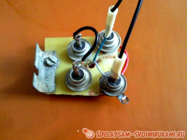
Suitable diode assemblies are used in computer power supplies. In this assembly there are two Schottky diodes with a common cathode, they need to be paralleled. For our charger suitable diodes with a current of not less than 15 A.
![]()
It should be borne in mind that in such assemblies the cathode is connected to the housing, so these diodes should be installed on the radiator through an insulating spacer.
It is necessary to adjust the upper voltage limit again, taking into account the voltage drop across the protection diodes. To do this, set the voltage potentiometer on the DC-DC converter board to 14.5 volts measured by the multimeter directly on the output terminals of the charger.
How to charge the battery
Wipe the battery with a cloth soaked in a solution of soda, then dry. Turn out the plugs and check the electrolyte level, if necessary, top up with distilled water. The plugs during the charge must be inverted. Do not put any debris or dirt inside the battery. The room in which the battery is charged should be well ventilated.
Connect the battery to the charger and turn the device on. During the charge, the voltage will gradually increase to 14.5 volts, the current will decrease with time. The battery can be conditionally considered charged when the charging current drops to 0.6 - 0.7 A.
The automatic charger is designed for charging and desulphating 12-volt batteries with a capacity of 5 to 100 Ah and estimating their charge level. The charger is protected against reverse polarity and short-circuiting the terminals. It uses microcontroller control, which ensures safe and optimal charging algorithms: IUoU or IUIoU, with subsequent charging to full charge. Charging parameters can be adjusted for a specific battery manually or select already embedded in the control program.The basic modes of operation of the device for the presets included in the program.
>>
Charging mode - the menu "Charge". For batteries with a capacity of 7Ah to 12Ah, the default algorithm is IUoU. It means:
- first step - charging with a stable current of 0.1C until the voltage reaches 14.6V
- second phase - a charge with a stable voltage of 14.6V, until the current drops to 0.02C
- third stage - maintaining a stable voltage of 13.8V, until the current drops to 0.01C. Here C is the battery capacity in Ah.
- fourth stage - charge. At this stage, the battery voltage is monitored. If it falls below 12.7V, the charge starts from the very beginning.
For starter batteries, we use the IUIoU algorithm. Instead of the third stage, the current stabilization is turned on at the level of 0.02C to reach the voltage on the battery 16V or after a time of about 2 hours. At the end of this stage, charging stops and charging begins.
>> The desulfation mode is the "Training" menu. Here the training cycle is carried out: 10 seconds - a discharge with a current of 0.01С, 5 seconds - a charge of 0.1C. The charge-discharge cycle continues until the battery voltage rises to 14.6V. Next - the usual charge.
>>
The battery test mode allows you to estimate the discharge level of the battery. The battery is charged with a current of 0.01C for 15 seconds, then the voltage measurement mode on the battery is switched on.
>> Control and training cycle. If you pre-connect an additional load and activate the "Charge" or "Training" mode, in this case, first the battery will be discharged to a voltage of 10.8 V, and then the corresponding selected mode will turn on. In this case, the current and discharge time are measured, so an approximate battery capacity is calculated. These parameters are displayed on the display after charging is completed (when "Battery charged" appears) when the "select" button is pressed. As an additional load, you can use a car incandescent lamp. Its power is selected based on the required discharge current. Usually it is set equal to 0.1С - 0.05С (current of 10 or 20 hour discharge).
Scheme of the charging machine for 12V battery
Schematic diagram of an automatic vehicle

Picture of an automatic car charger board
The basis of the scheme is the microcontroller AtMega16. Moving through the menu is done with the buttons " left», « to the right», « choice". The Reset button exits any memory operation mode in the main menu. The main parameters of the charging algorithms can be configured for a specific battery, for this there are two configurable profiles in the menu. The configured parameters are stored in non-volatile memory.
To get to the settings menu, you must select any of the profiles, press the " choice", choose " installations», « profile settings", Profile П1 or П2. After selecting the desired parameter, press " choice". Arrows « left" or " to the right"Will be replaced by the arrows" up" or " down", Which means that the parameter is ready for change. Select the desired value with the buttons "left" or "right", confirm with the button " choice". The display shows "Saved", which means the value is written to the EEPROM. For more information on setting up, see the forum.
Control of the main processes is entrusted to the microcontroller. In his memory is recorded control program , in which all the algorithms are laid. The power supply is controlled by PWM from the output of the PD7 MK and the simplest DAC on the elements R4, C9, R7, C11. Measurement of battery voltage and charging current is carried out by means of the microcontroller itself - built-in ADC and controlled differential amplifier. Voltage of the battery to the input of the ADC is supplied from the divider R10 R11.

The charge and discharge current are measured as follows. Voltage drop from the measuring resistor R8 through the divider R5 R6 R10 R11 is fed to the amplifier stage, which is located inside the MK and connected to the terminals PA2, PA3. Its gain is set programmatically, depending on the current being measured. For currents less than 1A, the gain (KV) is set to 200, for currents above 1A KU = 10. All information is displayed on the LCD, connected to the ports PB1-PB7 on a four-wire bus.
Protection against reverse polarity is performed on transistor T1, signaling of wrong connection - on elements VD1, EP1, R13. When the charger is plugged into the network, the T1 transistor is closed with a low level from the PC5 port, and the battery is disconnected from the charger. It is connected only when you select a battery type and memory mode in the menu. This also ensures the absence of sparking when the battery is connected. If you try to connect the battery in the wrong polarity, the buzzer EP1 and the red LED VD1 will sound, signaling a possible accident.
During charging, the charging current is constantly monitored. If it becomes zero (the terminals with the battery removed), the device automatically goes to the main menu, stopping the charge and disconnecting the battery. The transistor T2 and the resistor R12 form a discharge circuit that participates in the charge-discharge cycle of the desulfurizing charge and in the battery test mode. The discharge current of 0.01C is set by PWM from the PD5 port. The cooler turns off automatically when the charging current drops below 1.8A. Controls the cooler port PD4 and transistor VT1.
Resistor R8 - ceramic or wire, power not less than 10 W, R12 - also 10W. The rest - 0.125W. Resistors R5, R6, R10 and R11 must be applied with an acceptable deviation of not worse than 0.5%. This will determine the accuracy of the measurements. Transistors T1 and T1 are preferably used as indicated on the diagram. But if you have to choose a replacement, it must be taken into account that they must be opened with a voltage on the gate 5B and, of course, must withstand a current of not less than 10A. For example, transistors with marking 40N03GP, which are sometimes used in the same BP of the ATX format, in the 3.3V stabilization circuit.

LCD - WH1602 or similar, on the controller HD44780, KS0066 or compatible with them. Unfortunately, these indicators may have a different pin layout, so you may have to develop a printed circuit board for your instance


Rebuilding the BP-ATX under the charger
Scheme of electrical adjustment of standard ATX
In the control circuit, it is better to use precision resistors, as described in the description. When using tuners, the parameters are not stable. it is checked on own experience. When testing this memory, I performed a full cycle of discharging and charging the battery (discharge to 10.8V and charge in training mode, it took about a day). Heating the ATX PSU of the computer is not more than 60 degrees, and the MC module is even smaller.


Problems in the configuration was not, it started right away, only adjustment is necessary for the most accurate readings. After demonstrating the work to a friend-car enthusiast of this charger, the application immediately went to make one more copy. The author of the scheme - Slon , assembly and testing - sterc .
AUTOMATIC CHARGING DEVICE AUTOMOBILE
Sooner or later, every motorist has problems with the battery. I did not escape this fate either. After 10 minutes of unsuccessful attempts to start my car, I decided that it is necessary to purchase or make the charger itself. In the evening making an audit in the garage and finding there a suitable transformer decided to do the charging himself.
There, among the unnecessary junk, I found a voltage regulator from the old TV, which in my opinion will work fine as a case.

Proshtudirovan vast boundless spaces of the Internet and really appreciated their strength has probably chosen the most simple scheme.

Having printed out the scheme he went to his neighbor, who is fond of radio electronics. He within 15 minutes typed me the necessary details, cut off a piece of foil-shaped textolite and gave a marker for drawing the boards. Spending about an hour of time, I drew an acceptable fee (the installation of spacious body dimensions allow). I will not tell you how to etch the board, there is a lot of information about this. I took my creation to a neighbor, and he etched it to me. In principle, it was possible to buy a circuit board and do everything on it, but as they say to the gifted horse ....
Having drilled all the necessary holes and displaying the pin-hole of the transistors on the monitor screen, I took up the soldering iron and after about an hour I had a ready payment.

The diode bridge can be bought in the market, the main thing that it was designed for a current of at least 10 amperes. I have found D 242 diodes, their characteristics are quite suitable, and on a piece of textolite I soldered the diode bridge.
The thyristor must be installed on the radiator, as it is noticeably heated during operation.

Separately, I must say about the ammeter. He had to buy in the store, there the seller consultant picked up and shunt. The circuit decided to modify a little and add a switch, so that the voltage on the battery could be measured. Here, too, a shunt was needed, but when measuring the voltage, it is not connected in parallel, but in series. The calculation formula can be found on the Internet, I will add from myself that the power of dissipation of shunt resistors is of great importance. According to my calculations, it should have been 2.25 watts, but I had a 4-watt shunt. The reason is unknown to me, I do not have enough experience in such cases, but, having decided that basically I need indications of an ammeter, and not a voltmeter, I met it. Moreover, in the voltmeter mode, the shunt was noticeably heated for 30-40 seconds. So, having collected all the necessary things and having checked everything on the stool, I took up the case. Completely dismantling the stabilizer, I took out all of its stuffing.

After marking the front wall, I drilled holes for a variable resistor and switch, then drilled a small diameter around the hole to drill a hole for the ammeter. Sharp edge of the finalized file.

Slightly breaking his head over the location of the transformer and the radiator with a thyristor, he stopped on this option.

I bought a couple of clips "crocodile" and all-charging is ready. The peculiarity of this scheme is that it works only under load, so by collecting the device and not finding voltage on the terminals with a voltmeter, do not rush me to scold. Just hang on the conclusions at least an automobile light bulb, and you will be happy.

Transformer take with voltage on the secondary winding 20-24 volts. Stabilitron D 814. All other elements are listed in the diagram.
The car's on-board network until the power plant starts to power the battery. But she does not produce electrical energy herself. The battery is simply a receptacle of electricity that is stored in it and, if necessary, is given to consumers. After the expended energy is restored due to the work of the generator, which generates it.
But even the constant from the generator is not able to completely restore the energy expended. For this, periodic charging from an external source, not a generator, is necessary.
To make use of the chargers. These devices operate on a 220 V network. In fact, the charger is a conventional converter of electrical energy.
It takes an alternating current of 220 V, lowers it and converts it into a direct current with a voltage of up to 14 V, that is, up to the voltage that the battery itself gives out.
Now a large number of various chargers are being made - from primitive and protozoa to devices with a lot of various additional functions.
Sold and chargers, which, in addition to possible recharging the battery installed on the car, can also launch the power plant. Such devices are called charging and starting.
There are also autonomous charging and starting devices that can recharge the battery or start the motor without connecting the device itself to the 220 V network. Inside of such a device besides the equipment that converts electric energy, there is also that makes such a device autonomous, although the battery of the device after each delivery of electricity requires charging.
Video: How to make the simplest charger
As for conventional chargers, the simplest of them consists of just a few elements. The main element of such a device is a step-down transformer. It reduces the voltage from 220 V to 13.8 V, which are the most optimal for charging the battery. However, the transformer only lowers the voltage, but its conversion from alternating current to constant is performed by another element of the device - a diode bridge that produces rectification of the current and dividing it into positive and negative poles.
Behind the diode bridge, an ammeter is usually included in the circuit, which shows the current strength. The simplest device uses an arrow ammeter. In more expensive devices, it can be digital, also a voltmeter can be built in addition to the ammeter. In some chargers, there is a choice of voltage, for example, they can be charged as a 12-volt battery, and 6-volt.
From the diode bridge, wires with "plus" and "minus" terminals come out, which connect the device to the battery.
All this is enclosed in a housing from which a wire with a plug for connecting to the network comes out and wires with terminals. To protect the entire circuit from possible damage, it includes a fuse.
In general, this is the whole scheme of a simple charger. They charge the battery relatively easily. Connect the terminals of the device to the terminals, it is important not to confuse the poles. Then the device is connected to the network.
At the very beginning of charging, the device will supply a voltage of 6-8 amperes, but as charging, the current will decrease. All this will be displayed on the ammeter. If the battery is fully charged, the ammeter needle will drop to zero. This is the whole process of charging the battery.
Simplicity of the charger circuit provides the possibility of its self-manufacturing.
Self-made car charger
Now consider the simplest chargers that you can make yourself. The first to be a device, which in principle is very similar to the described.

The diagram shows:
S1 - power switch (toggle switch);
FU1 - fuse for 1A;
T1 - transformer TH44;
D1-D4 - diodes D242;
C1 - capacitor 4000 mkF, 25 V;
A - ammeter at 10A.
So, to make a self-made charger you need a step-down transformer TS-180-2. Such transformers were used on old tube TVs. Its feature is the presence of two primary and secondary windings. Each of their secondary windings at the output has 6.4V and 4.7A each. Therefore, in order to obtain the 12.8V required for charging the battery, which this transformer is capable of, it is necessary to make a serial connection of these windings. To do this, a short wire with a cross section of at least 2.5 mm is used. sq. m. The jumper connects not only the secondary windings but also the primary windings.
Video: The simplest battery charger
Further, a diode bridge is required. To create it, 4 diodes are taken, designed for a current strength of at least 10 A. These diodes can be fixed to a textolite plate, and then make the correct connection. Connect the wires to the output diodes, which the device will connect to the battery. At this, the assembly of the device can be considered complete.
Now about the correctness of the charging process. When connecting the device to the battery, you can not mix up the polarity, otherwise you can disable both the battery and the device.
When connected to the battery, the device must be completely de-energized. Plug it into the network can only after connecting to the battery. Disconnect from the battery it also follows after disconnecting from the network.
Do not connect to the device without a means of reducing the voltage and current, otherwise the device on the battery will supply a current of high power, which can damage the battery. As a reducing device, a conventional 12-volt lamp can be used, which is connected to the output terminals in front of the battery. The lamp will be lit when the device is operating, thereby partially taking over the voltage and current. Over time, after a partial charge of the battery, the lamp from the circuit can be eliminated.
When charging periodically you need to check the degree of battery charging, for which you can use a multimeter, a voltmeter or a load plug.
A fully charged battery should check at least 12.8 V when testing the voltage on it, if the value is lower, further charging is required to bring this figure to the required level.
Video: Car charger for own car battery
Since this circuit does not have a protective housing, it is not necessary to leave the device unattended during operation.
And let this device does not provide the optimal 13.8 V at the output, but for recharging the battery is quite suitable, although after about two years of using the battery you still need to charge it with a factory device that provides all the optimal parameters for charging the battery.
Transformerless charger

An interesting design is the scheme of a self-made device that does not have a transformer. Its role in this device is performed by a set of capacitors designed for a voltage of 250 V. Such capacitors must be at least 4. The capacitors themselves are connected in parallel.
A resistor is connected in parallel to the capacitor bank, designed to extinguish the residual voltage after disconnecting the device from the network.
Next, you need a diode bridge to work with an allowable current of at least 6 A. It is connected to the circuit after a set of capacitors. And then the wires are connected to it, with which the device will be connected to the battery.
Homemade battery chargers usually have a very simple design, and in addition to that and increased reliability just because of the simplicity of the circuit. Another plus from the manufacture of charging by one's own hands is the relative cheapness of the components and, as a result, the low cost of the device.
Why the prefabricated structure is better than the purchase
The main task of this technique is to maintain the required battery level of the car if necessary. If the discharge of the battery occurred near the house, where there is the right device, then there will be no problems. Otherwise, when there is no suitable technique for powering the battery, and the means are also not enough, you can assemble the device yourself.
The need to use auxiliary means to make up the battery of a car is due primarily to low temperatures during the cold season, when a half-discharged battery is the main and sometimes not completely solvable problem unless the battery is recharged in time. Then homemade battery chargers to power car batteries will be a rescue for users who do not plan to invest in such equipment, at least for the moment.
Operating principle
To a certain level of the battery, the car can be powered from the vehicle itself, or more precisely from the power generator. After this node is usually installed relay, responsible for setting the voltage is not more than 14.1V. To ensure that the battery is fully charged, you need a higher value of this parameter - 14.4V. Accordingly, for the implementation of such a task, the battery is used.
The main components of this device are a transformer and a rectifier. As a result, a constant current is supplied to the output with a voltage of a certain value (14.4 V). But why is there a runaway with the voltage of the battery itself - 12V? This is done in order to provide the possibility to charge the battery discharged to a level when the value of this battery parameter is equal to 12V. If the charge is characterized by the same parameter, then as a result, battery power will become a difficult task.
Watching video, the simplest device for charging a battery:
But here there is a nuance: a slight excess of the battery voltage level is not critical, whereas a significantly overestimated value of this parameter will very badly affect the performance of the battery in the future. The principle of operation, which is different, even the simplest charger for powering a car battery, is to increase the level of resistance, which will lead to a decrease in the charging current.
Accordingly, the higher the voltage value (tends to 12V), the lower the current. For normal operation of the battery it is desirable to set a certain value of the charging current (about 10% of the capacity). In a hurry, the temptation to change the value of this parameter is greater, however, this is fraught with negative consequences for the battery itself.
What will be required to manufacture the battery?
The basic elements of a simple design: a diode and a heater. If correctly (sequentially) connect them to the battery, you can achieve the desired - the battery will be charged after 10 hours. But for fans of saving electricity this solution may not be suitable, because the consumption in this case will be about 10 kW. The work of the received device is characterized by low efficiency.

Basic Elements of Simple Design
But to create a suitable modification, it is necessary to slightly modify individual elements, in particular, a transformer whose power should be at the level of 200-300 watts. In the presence of old technology, this part is suitable from a conventional lamp TV. For the organization of the ventilation system, a cooler is useful, it is best if it is from a computer.
When a simple charger is created to power the battery with one's own hands, the transistor and the resistor are also the main elements. To adjust the design, you need a compact outside, but a fairly capacious body made of metal, a good option - a box from the stabilizer.
In theory this kind of technology can be assembled even by a novice radio amateur who had not previously encountered complex circuits.
The scheme of a simple device for charging the battery
The main difficulty is the need to modify the transformer. At this power level, the windings are characterized by low voltage indices (6-7V), the current will be equal to 10A. Usually, a voltage of 12V or 24V is required, depending on the type of battery. To obtain such values at the output of the device, it is necessary to provide a parallel connection of the windings.
Phased assembly
A homemade battery charger to power the car battery begins with the preparation of the core. Winding the wire on the windings is done with maximum compaction, it is important that the coils fit tightly to each other, and no lumens remain. One should not forget about isolation, which is placed with an interval of 100 turns. The section of the primary winding wire is 0.5 mm, the secondary wire is 1.5 to 3.0 mm. If we take into account that at a frequency of 50 Hz, 4-5 turns can provide a voltage of 1V, respectively, to obtain 18V, about 90 turns are required.
Next, a diode of suitable power is selected to withstand the loads applied to it in the future. The best option is the generator diode of the car. To avoid the risk of overheating, it is necessary to ensure an efficient circulation of air inside the body of such a device. If the box is not perforated, you should take care of this before starting the assembly. The cooler must be connected to the output of the charger. Its main task is cooling of the diode and winding of the transformer, which is taken into account when selecting the site for installation.
Watch the video, detailed instructions on how to make:
The circuit of a simple charger for supplying a car battery contains a variable resistor as well. For the normal operation of charging, you need to get a resistance of 150 ohms and a power of 5 watts. The model of the resistor KU202H is more in line with these requirements. You can choose a different option, but its parameters should be similar in value to those indicated. The task of the resistor is to adjust the voltage at the output of the device. The model of the transistor KT819 is also the best option from a number of analogues.
Evaluation of efficiency, cost
As you can see, if you need to assemble a self-made battery charger for a car battery, its circuit is more than easy to implement. The only difficulty is the arrangement of all the elements and their installation in the body with the subsequent connection. But such work is difficult to call laborious, and the cost of all used parts is extremely small.
Some of the details, and, perhaps, all probably for the radio amateurs at home, for example, a cooler from an old computer, a transformer from a tube TV, an old case from a stabilizer. As for the degree of efficiency, such devices, assembled with their own hands, do not have a very high efficiency, but, as a result, they still cope with their task.
We look video, useful advice of a specialist: