Antipyretics for children are prescribed by a pediatrician. But there are situations of emergency care for fever, when the child needs to give the medicine immediately. Then the parents take responsibility and apply antipyretic drugs. What is allowed to give to infants? How can you bring down the temperature in older children? Which medications are the safest?
Battery protection from deep discharge ...
The scheme is not mine. Just repeat ... Use where you need ... Recorders, tape recorders, etc. ...
DEVICE to protect 12v batteries from deep discharge and short circuit with automatic shutdown of its output from the load.
CHARACTERISTICS
The voltage on the battery, at which the trip occurs - 10 ± 0.5 V. (I got exactly 10.5 V)
The current consumed by the device from the battery in the switched on state is not more than - 1 mA
The current consumed by the device from the battery in the switched off state, no more - 10мкА
The maximum permissible direct current through the device is 5 A. (30 Watt bulb 2.45 A - Mosfit without radiator +50 degrees (room +24))
The maximum permissible short-time (5 s) current through the device is 10A
Turn-off time in case of a short circuit at the output of the device, not more than - 100 μs
OPERATION OF THE DEVICE
Connect the device between the battery and the load in the following sequence:
- Connect the terminals to the wires, observing the polarity (orange wire + (red), to the battery,
- connect to the device, observing the polarity (positive terminal marked with +), load terminals.
In order for the output of the device to appear voltage, it is necessary to short-circuit the negative output to the negative input. If the load other than the battery is fed by another source, then this should not be done.
DEVICE WORKS AS FOLLOWS;
When switching to battery power, the load discharges it to the protective device's trip voltage (10 ± 0.5V). When this value is reached, the device disconnects the battery from the load, preventing its further discharge. The device will turn on automatically when the voltage is applied from the load side to charge the battery.
In the case of a short circuit in the load, the device also disconnects the battery from the load, it will automatically turn on if the load side loads above 9.5V. If there is no such voltage, then the output minus terminal of the device and the minus battery must be short-circuited. Resistors R3 and R4 set the pickup threshold.
Spare parts
1. Mounting plate (not necessarily can be a canopy)
2. Field transistor any, pick up on A and B. I took RFP50N06 N-channel 60V 50A 170 deg
3. Resistors 3 for 10 kom, and 1 for 100 kom
4. Bipolar transistor KT361G
5. Zener diode 9.1 V
Extras. It is possible to connect the terminals + Micrik to start. (I did not do it myself because I will have a part of another device)
6. It is possible on the LED to the input and output for clarity (Select the resistor, solder in parallel)
Soldering iron + tin + spirtokanifol + pliers + wiring + multimeter + load, etc. and so on
Soldering by tin-and-salt. I do not want to bait on pay. Leyauta no.
Load 30 Watts, Current 2.45 A polevik is heated to +50 degrees (room +24). Cooling is not necessary.
I've been loading 80 watts ... I-VAC. The temperature is 120 degrees. The tracks began to blush ... Well, you know you need a radiator, Well-trodden paths.
Hello.
Necessity forced to assemble this device. I think this topic will be relevant to those who have more than two cars in use. As a rule, one is operated in winter, the other in summer. That is, one of them the season in the year is in the garage or in the parking lot. And while he stands there, we do not know how his battery feels.
No, of course you can "feel" it periodically with a voltmeter or buy a ready indicator (for example, inserted into the cigarette lighter).
Some of these devices gladly notify us when the battery has already almost reached the fur animal of the Arctic fox, or already it has become densely settled there and it is necessary to go buy a new battery.
Therefore, I wanted to make such an indicator that would show the intermediate values of the residual charge of the battery. Well, for example, - more than 75%, 75%, 50% and 25% of the charge. And so lazily to care for the health of the battery, so as not to climb under the hood of the car and not to unpack the charger unnecessarily.
I was looking for acceptable schemes in the internet for a long time. I collected some. But it's not that. The hysteresis of the display's operation is such that it would be better if it were not, this indication, it's easier and more reliable to measure it. Then the settings float and there is no stability, then generally the brightness of the LED changes smoothly depending on the voltage on the battery and go find out what's on it.
And now I found one scheme on some Portuguese site. Simple to improper and kind of should work. It is built on the operational amplifier UA741. Here she is:
In it, I changed only the nominal value of a zener diode from 6.2 volts to 7.5 volts. Triggers are clear. The LED lights up at the desired set point (adjustable by trimmer R2). R2 is better to use multi-turn, because it is not easy to set the desired voltage for them. Sensitivity in the trigger zone is very gentle and almost invisible rotation of the adjustment screw takes the right voltage to the side.
To adjust it is necessary, using an accurate regulated laboratory power source with a digital voltmeter, showing tenths (or better hundredths, I simultaneously included a digital tester) of the volt.
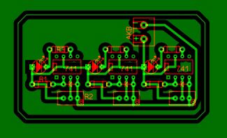
Since I wanted to see the degree of charging of the battery in the gradations of the above, I assembled a circuit of three such units. Here is the drawing of the signet:

When the battery is fully charged, the voltage on it is higher than 12.7 V, while no LEDs are lit and everything is fine (Photo 1).

The first unit lights the green LED when the voltage on the battery terminals is less than 12.5 V, which corresponds to about 75% of the battery charge (photo 2).

The second unit lights the yellow LED at a voltage below 12.2 V, which is about 50% of the charge (Photo 3).

Well, the third unit lights up red, it lights up at a voltage below 11.7 V or about 25% of the residual charge of the battery (Photo 4).

The values of voltage settings I used for AGM batteries (I have such cars on cars). For ordinary acids, they can be changed by setting R2.
The board was placed in a small (40mm x 70mm) housing. On the case, I placed an additional small-sized switch in the break of the positive wire for convenience, so as not to remove the clamps from the battery terminals, when measurements are not required and that the device does not consume at least a small current (about 20 mA, mainly determined by the current of the burning LEDs) . To the battery from the device is connected a double red-black wire with clamps at the ends (Photo 5).

The device is connected to the terminals of the battery standing in the garage of the car constantly. When necessary, going into the garage, without extra "dances" I turn on the switch on the device, I watch what color the "light bulbs" burn and see whether my battery is healthy or it needs to be "treated".
Good luck on the roads!
I think this topic will be relevant to those who have more than two cars in use. As a rule, one is operated in winter, the other in summer. That is, one of them the season in the year is in the garage or in the parking lot. And while he stands there, we do not know how his battery feels. No, of course you can "feel" it periodically with a voltmeter or buy a ready indicator, which is a lot on the same Ali-Express (for example, inserted into the cigarette lighter). But I wanted to make my indicator, which would show the intermediate values of the residual charge of the battery. Well, for example, - more than 75%, 75%, 50% and 25% of the charge. And I would like to so lazily to care for the health of the battery, so as not to climb under the hood of the car once again and not to unpack the charger without the need.
I was looking for acceptable schemes in the internet for a long time. I collected some. But it's not that. The hysteresis of the display's operation is such that it would be better if it were not, this indication, it's easier and more reliable to measure it. Then the settings float and there is no stability, then generally the brightness of the LED changes smoothly depending on the voltage on the battery and go find out what's on it. And now I found one scheme on some Portuguese site. Simple to improper and kind of should work. It is built on the operational amplifier UA741. Here she is:
In it, I changed only the nominal value of a zener diode from 6.2 volts to 7.5 volts. Triggers are clear. The LED lights up on the desired setting (adjustable by trimmer R2). R2 is better to use multi-turn, because it is not easy to set the desired voltage for them. Sensitivity in the trigger zone is very gentle and almost invisible rotation of the adjustment screw takes the right voltage to the side.
To adjust it is necessary, using an accurate regulated laboratory power source with a digital voltmeter, showing tenths (or better hundredths, I simultaneously included a digital tester) of the volt. Since I wanted to see the degree of charging of the battery in the gradations of the above, I assembled a circuit of three such units. Here is the drawing of the signet:
When the battery is fully charged, the voltage on it is higher than 12.7 V, while no LEDs are lit and everything is fine (Photo 1).
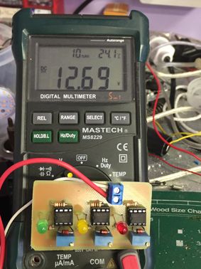
The first unit lights the green LED when the voltage on the battery terminals is less than 12.5 V, which corresponds to about 75% of the battery charge (photo 2).
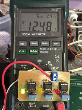
The second one lights the yellow LED at a voltage below 12.2 V, which is about 50% of the charge (Photo 3).
![]()
Well, the third, red, lights up at a voltage below 11.7 V or about 25% of the residual charge of the battery (Photo 4).

I used voltage settings for AGM batteries (I have them on cars). For ordinary acids they can be changed to others. The board was placed in a small (40 mm x 70 mm) housing. On the case, I placed an additional small-sized switch in the break of the positive wire for convenience, so as not to remove the clamps from the battery terminals, when measurements are not required and that the device does not consume at least a small current (about 20 mA, mainly determined by the current of the burning LEDs) . To the battery from the device is connected a double red-black wire with clamps at the ends (Photo 5).

The device is connected to the terminals of the battery standing in the garage of the car constantly. When necessary, going into the garage, without extra "dances" I turn on the switch on the device, I watch what color the "light bulbs" burn and see whether my battery is healthy or it needs to be "treated".
I think this topic will be relevant to those who have more than two cars in use. As a rule, one is operated in winter, the other in summer. That is, one of them the season in the year is in the garage or in the parking lot. And while he stands there, we do not know how his battery feels. No, of course you can "feel" it periodically with a voltmeter or buy a ready indicator, which is a lot on the same Ali-Express (for example, inserted into the cigarette lighter). But I wanted to make my indicator, which would show the intermediate values of the residual charge of the battery. Well, for example, - more than 75%, 75%, 50% and 25% of the charge. And I would like to so lazily to care for the health of the battery, so as not to climb under the hood of the car once again and not to unpack the charger without the need.
I was looking for acceptable schemes in the internet for a long time. I collected some. But it's not that. The hysteresis of the display's operation is such that it would be better if it were not, this indication, it's easier and more reliable to measure it. Then the settings float and there is no stability, then generally the brightness of the LED changes smoothly depending on the voltage on the battery and go find out what's on it. And now I found one scheme on some Portuguese site. Simple to improper and kind of should work. It is built on the operational amplifier UA741. Here she is:
In it, I changed only the nominal value of a zener diode from 6.2 volts to 7.5 volts. Triggers are clear. The LED lights up on the desired setting (adjustable by trimmer R2). R2 is better to use multi-turn, because it is not easy to set the desired voltage for them. Sensitivity in the trigger zone is very gentle and almost invisible rotation of the adjustment screw takes the right voltage to the side.
To adjust it is necessary, using an accurate regulated laboratory power source with a digital voltmeter, showing tenths (or better hundredths, I simultaneously included a digital tester) of the volt. Since I wanted to see the degree of charging of the battery in the gradations of the above, I assembled a circuit of three such units. Here is the drawing of the signet:
When the battery is fully charged, the voltage on it is higher than 12.7 V, while no LEDs are lit and everything is fine (Photo 1).
The first unit lights the green LED when the voltage on the battery terminals is less than 12.5 V, which corresponds to about 75% of the battery charge (photo 2).
The second one lights the yellow LED at a voltage below 12.2 V, which is about 50% of the charge (Photo 3).
![]()
Well, the third, red, lights up at a voltage below 11.7 V or about 25% of the residual charge of the battery (Photo 4).
I used voltage settings for AGM batteries (I have them on cars). For ordinary acids they can be changed to others. The board was placed in a small (40 mm x 70 mm) housing. On the case, I placed an additional small-sized switch in the break of the positive wire for convenience, so as not to remove the clamps from the battery terminals, when measurements are not required and that the device does not consume at least a small current (about 20 mA, mainly determined by the current of the burning LEDs) . To the battery from the device is connected a double red-black wire with clamps at the ends (Photo 5).
The device is connected to the terminals of the battery standing in the garage of the car constantly. When necessary, going into the garage, without extra "dances" I turn on the switch on the device, I watch what color the "light bulbs" burn and see whether my battery is healthy or it needs to be "treated".