Antipyretics for children are prescribed by a pediatrician. But there are situations of emergency care for fever, when the child needs to give the medicine immediately. Then the parents take responsibility and apply antipyretic drugs. What is allowed to give to infants? How can you bring down the temperature in older children? Which medications are the safest?
The marking of diodes is a short graphic symbol element, on the body of which is applied. The elemental base is now so diverse, the abbreviations are very significant. It is difficult to identify a diode: zener diode, tunnel, Gunn. There are varieties that resemble a gas discharge bulb. LEDs are on, completing confusion.
Semiconductor diodes
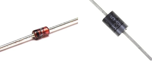
Perhaps, the section is called somewhat trivial, it was necessary to distinguish ordinary diodes from obsolete ones electron tubes, the most modern SMD modifications. Ordinary semiconductor diodes are the simplest mount of a radio amateur. The sidewall of the cylindrical body with a disk base, legs contains an easily discernible inscription painted with paint.
Semiconductor resistors. Distinguish with the naked eye?
The color of the case does not matter, the size indirectly indicates the power dissipated. Have high-power diodes there is often a thread under the radiator mounting nut. The result of calculating the thermal regime shows a lack of own capabilities of the hull, the cooling system is supplemented by a hinged element. Today, the power consumption drops, reducing the linear dimensions of the instrument cases. This allowed us to use glass. The new housing material is cheaper, durable, safer.
- The first place is occupied by a letter or digit, briefly characterizing the material of the element:
- Г (1) - germanium compounds.
- K (2) is a silicon compound.
- A (3) is gallium arsenide.
- And (4) - indium compounds.
- The second letter in our case is D. Diode rectifying, or pulsed.
- The third place was chosen by the figure that characterizes the applicability of the diode:
- Low-frequency, current below 0.3 A.
- Low-frequency, current 0.3 - 10 A.
- Not used.
- Pulse, the recovery time is more than 500 ns.
- Pulse, recovery time 150 - 500 ns.
- The same, recovery time 30 - 150 ns.
- The same, recovery time 5 - 30 ns.
- The same, recovery time 1 - 5 ns.
- Pulsed, the lifetime of minority carriers is less than 1 ns.
- The development number is compiled in two digits, it may be absent altogether. The denomination below 10 is complemented from the left by zero. For example, 07.
- The group number is indicated by a letter, it determines the differences between properties and parameters. The letter is often key, it can indicate working voltage, direct current, much more.
In addition to the labeling, reference books give graphs on which it is possible to solve the tasks of selecting the working point of a radio element. Information on the technology of production, the material of the hull, and the mass may be indicated. The information is provided to the equipment designer, the amateurs do not carry any practical meaning.
Imported notation systems differ from domestic ones, are well standardized. Therefore, with the help of special tables it is enough to find suitable analogues.
Color marking
Every radio amateur knows the difficulty of identifying diodes surrounded by a glass case. One face. At times, the manufacturer bothers to apply clear marks, multi-colored rings. According to the notation system, three characteristics are introduced:
- Tags of the regions of the cathode, anode.
- Color of the case, replaced by a color dot.
According to the state of things, at first glance, we distinguish the types of diodes:
- The family D9 is marked with one or two colored rings of the anode region.
- Diodes KD102 in the area of the anode are indicated by a color point. The case is transparent.
- KD103 have a complementary point color casing, excluding 2D103A, denoted by the white point of the anode region.
- The families KD226, 243 are marked with a ring of the cathode region. There are no other labels.
- Two colored rings around the cathode can be seen from the KD247 family.
- The KD410 diodes are indicated by a dot in the anode region.
There are other clearly distinguishable marks. A more detailed classification can be found by studying the publication of Kashkarov AP. On the marking of radioelements. Beginners are concerned about the location of the cathode and the anode.
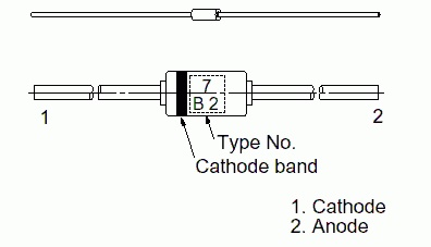
- You see: one side of the cylinder is equipped with a dark stripe - a cathode is found. Color can be part of the labeling discussed today.
- Being able to operate a multimeter, it is easy to find the anode. Electrode, where we attach a red dipstick to open the valve (hear the bell).
- The new diode is equipped with an antenna antenna longer than the cathode.
- Through the glass housing of the LED, let's look through the magnifying glass: the metal anode resembles the tip of a spear, smaller than the cathode.
- The old diodes contained an arrow marking. The point is the cathode. Allows you to determine the direction of inclusion visually. Modern radio monitors have to train smartness, visual acuity, accuracy of manipulation.
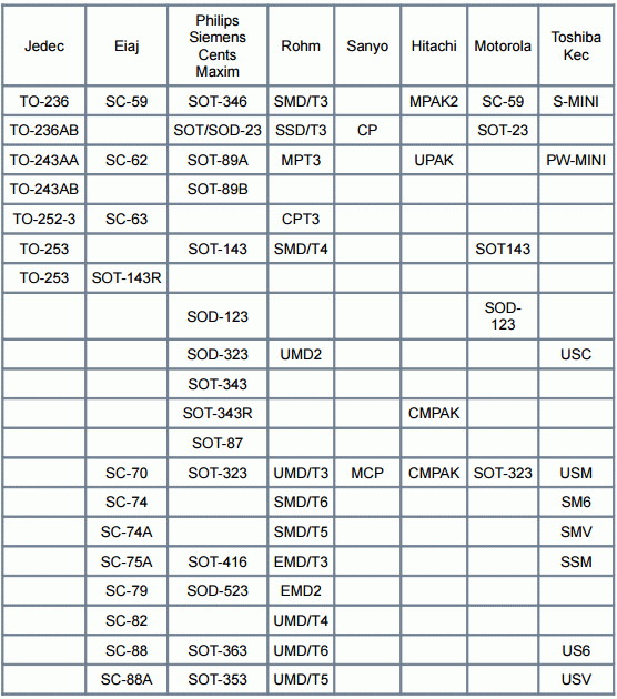
Foreign products received a different designation system. When choosing an analog, use special matching tables. The rest of the import base differs little from the domestic one. The marking is carried out according to the standards of JEDEC (USA), European system (PRO ELECTRON). Colorful tables of decoding the color code are widely represented by network sources.
Color marking
SMD diodes
In SMD, the diode housing is sometimes so small that there is no marking at all. The characteristics of the instruments depend little on the dimensions. The latter strongly affect the dissipated power. The larger current passes through the circuit, larger dimensions must have a diode, which removes the heat (the Joule-Lenz law) that arises. According to the written marking of the SMD diode can be:
- Complete.
- Shortened.
- Absence of marking.
SMD elements in the total electronics occupy about 80% of the volume. Surface mounting. Invented method electrical connection is most convenient for automated assembly lines. The marking of the SMD diode may not coincide with the filling of the housing. With a large volume of production manufacturers begin to cunning, put inside is not something that is marked with a symbol. From a large number of uncoordinated standards, there is confusion about the use of the pinouts (for diodes - microassemblies).
Housing
The marking can include 4 digits indicating the type of housing. Directly does not correspond in any way to dimensions, ask more in detail a question in GOST Р1-12-0.062, GOST Р1-12-0.125. Lovers who can not afford to get regulatory acts, it is easier to use reference tables. We keep in mind the fact: the SMD corps from the firm to the company may differ in detail. As each manufacturer guessed the element base for its own products. Samsung has one distance from the motherboard of the washing machine, LG is different. Dimensions of SMD enclosures will require different, heat removal conditions, other requirements are met.
Therefore, purchasing, according to the digits of the directory element, make additional measurements, if this is important. For example, in the case of repair of household appliances. Otherwise, the purchased diodes may not stand at their destination. Fans with SMD do not communicate due to the apparent complexity of editing, but for masters this is common, because microelectronics is impossible without such a successful technology.
Choosing a diode, it is worth keeping in mind the fact: many cases can be essentially the same, but they are labeled differently. Some designations are completely devoid of numbers. It is convenient to use search engines. The resulted cross-table of conformity of standard sizes is taken from a site selixgroup.spb.ru.
SMD diodes are often available in the SOD123 package. If one end has a strip of any color, or embossed, it is the cathode (the place where you need to apply a negative polarity to open the p-n-junction). If only on the body there are inscriptions, then this is the designation of the hull. If lines of more than one - characterizing the shell larger.
Item type and manufacturer
Clearly, the type of case for the designer is a minor thing. Some heat will scatter through the surface of the element. From this point of view, we need to consider a diode. Otherwise, the following characteristics are important:
- Working and reverse voltage.
- Maximum allowable current through the p-n-junction.
- Power dissipation, etc.
These parameters for semiconductor diodes are indicated by reference books. Marking helps to find the right among the mountain of waste paper. In the case of an SMD element, the situation is much more complicated. There is no unified system of notation. And at the same time it's easier - the parameters from one diode to another do not change too much. The power dissipation, the working voltage, differs by and large. Each SMD element is marked with a sequence of 8 letters and digits, and part of the familiarity can not be used at all. This is the case with veterans of the industry, giants of the electronics industry:
- Motorola (2).
- Texas Instruments.
- Now converted and partially sold by Siemens (2).
- Maxim Integrated Product.
The mentioned manufacturers are labeled at times with deuce MO, TI, SI, MX. In addition, a couple of letters address:
- AD - Analog Devices;
- HP - Hewlett-Packard;
- NS - National Semiconductors;
- PC, PS - Philips Components, Semiconductors, respectively;
- SE - Seiko Instruments.
Of course, the appearance of the case does not always determine the manufacturer, then the search engine should immediately dial the alphanumeric sequence. Other examples are noted: diode assembly NXP in the case SOD123W does not carry any information other than the above line. The manufacturer considers this information sufficient. Because the SOD itself is decrypted as a small outline diode. We find the other information on the official website of the company (nxp.com/documents/outline_drawing/SOD123W.pdf).
The space for printing is limited, which explains such simplifications. The manufacturer tries to minimize the difficulty of performing the marking. Laser or screen printing is often used. This will fit 8 characters on an area of only 4 square millimeters (Kashkarov AP "Labeling Radio Elements"). In addition to the diodes indicated, the following types of enclosures are used:
- Cylindrical glass MELF (Mini MELF).
- SMA, SMB, SMC.
- MB-S.
To top it off, the same alphanumeric code sometimes corresponds to different elements. In this case, it is necessary to analyze the electrical circuit. Depending on the purpose of the diode, the operating current, voltage, and some other parameters are assumed. According to the catalogs, it is recommended to try to identify the manufacturer, since the parameters have a non-significant spread, making it difficult to correctly identify the product.
other information
In addition to the times indicated, there are other information. Lot number, date of issue. Such measures are taken, making it possible to track new modifications of the goods. The design department issues correcting documentation, furnished with a number, there is a date. And if the assembly department has to take into account the peculiarity, when practicing the changes introduced, the masters should read the markings.
If you assemble the equipment using new drawings (electrical circuits), using the old parts, you will not get what you expected. Simply put, the product will fail, it is encouraging if it is a reversible process. Nothing will burn. But even in this case, the shop manager will probably get a hat, the goods will have to be altered as part of the unaccounted factor.
Besides diodes
On the basis of p-n-junctions, a billion modifications of diodes have been created. This includes varicaps, zener diodes and even thyristors. Each family has features, with diodes a lot of similarities. We see three global views:
- the element base of a relatively large size that is obsolete today, a clearly discernable marking formed by standard letters and numbers;
- glass enclosures, equipped with color symbols;
- SMD elements.
Analogues are selected based on the conditions specified above: power dissipation, limiting voltage, current passing.
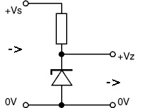
The zener diode is also called a reference diode. Zener diodes are designed to stabilize the output voltage when the input voltage fluctuates or when the load value changes ( fig. 1 ).
Fig. 1 - Functional diagram of the zener diode
For example, if you need to get 5 V on the load, and the power supply voltage fluctuates within 9 V. In order to reduce and stabilize the voltage supplied from the power supply, zener diodes are used up to the required 5 V. Of course, you can apply and voltage stabilizers, in this case, suitable or. However, their use is not always justified, so in some cases they use zener diodes.
Outwardly, they are similar to diodes and have the form shown in fig. 2.
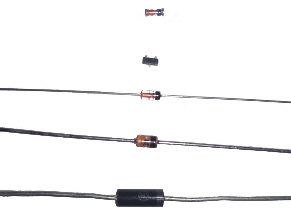
Fig. 2 - Appearance of zener diodes
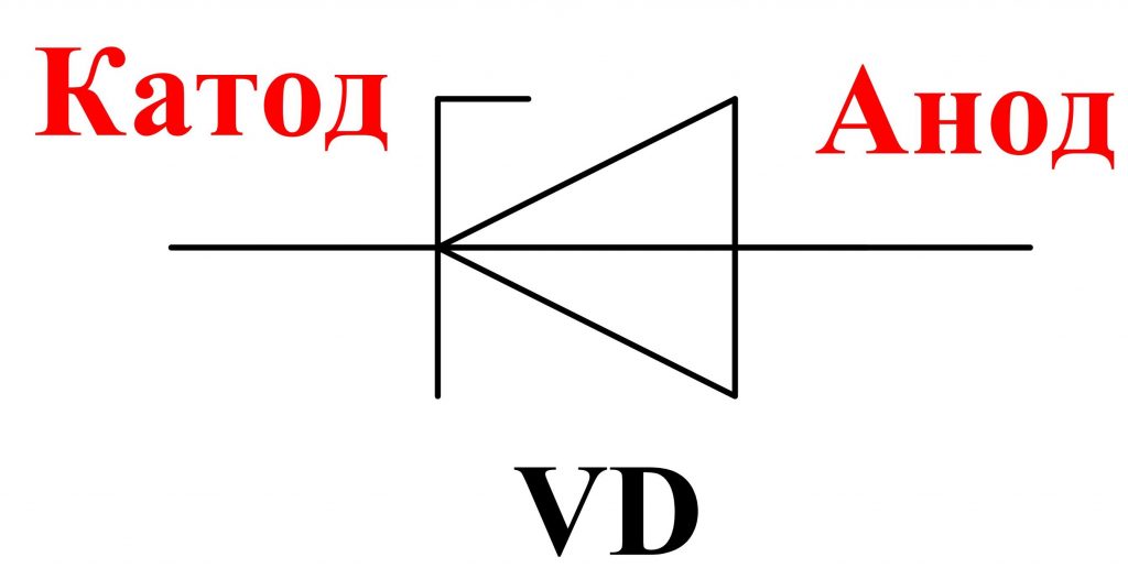
The designation of zener diodes on the diagrams is given in fig. 3 .
Principle of operation of a zener diode
Now let's look at how the zener diode performs voltage stabilization.
The main characteristic of a zener diode, however, like a diode, is the current-voltage characteristic (VAC). It shows the dependence of the current flowing through the zener diode on the magnitude of the applied voltage ( fig. 4).
The VAC of a zener diode has two branches.
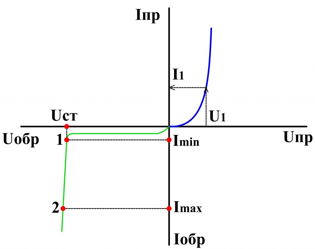
Fig. 4 - VAC of a zener diode
The direct branch of the zener diode does not practically differ from the straight branches of conventional diodes and for the latter it will also be a working one.
The normal mode of operation of a zener diode is when it is under reverse voltage. Therefore, the reverse branch will be working for him. It is located almost parallel to the axis of the reverse currents. On this curve, there are two points: 1 and 2 (fig. 4), between them is the working area of the zener diode.
At a certain value of the reverse voltage U art. an electrical breakdown occurs p — n transition of a zener diode and through it already a considerable current flows. However, when the current varies widely from the value Imin before Imax voltage drop across a zener diode U art. practically does not change ( fig. 4 ). Due to this property, the voltage is stabilized.
If the current flowing through the zener diode exceeds the value Imax , then the semiconductor structure will overheat, there will be a thermal breakdown and the zener diode will fail.
To power supply Uip The zener diode is connected via a current-limiting resistor Roger , which serves to limit the current flowing through the zener diode, and also together with it forms a voltage divider ( fig. 5 ).
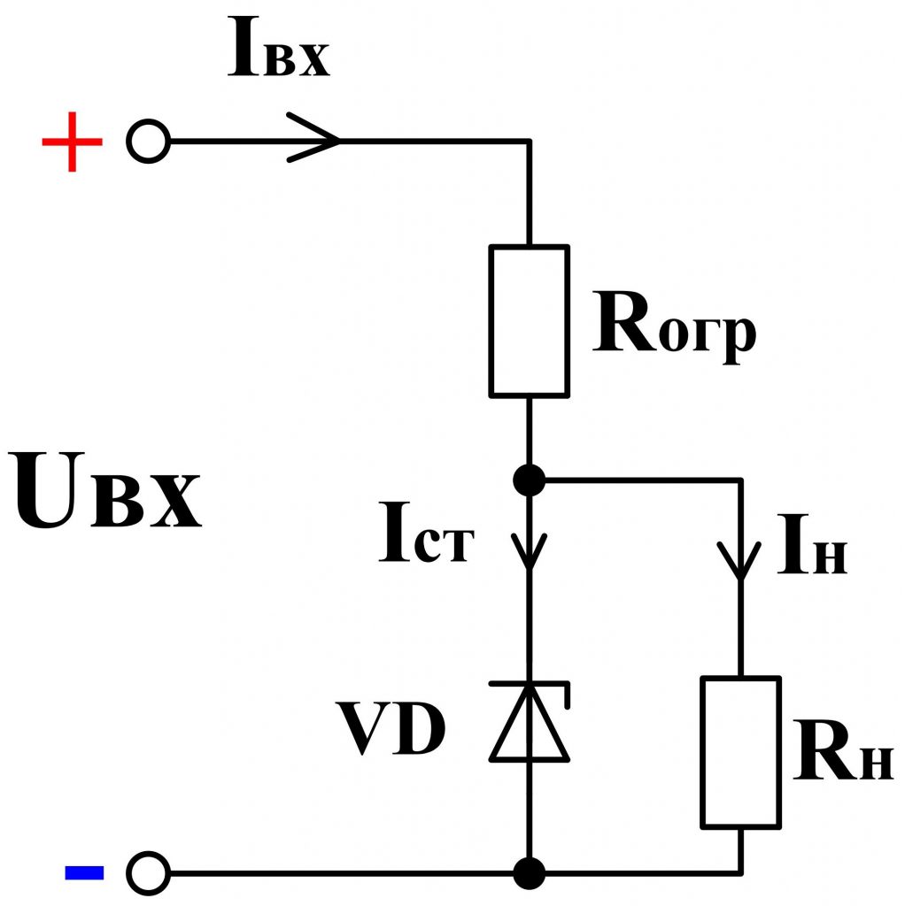
Fig. 5 - Zener diode connection circuit
Note, unlike the diode, the zener diode is connected in the reverse direction, ie, the "+" of the power supply is applied to the cathode, and "-" to the anode.
In parallel to the terminals of the zener diode, the load is connected R mr. , at the terminals of which it is required to maintain a stable voltage.
The process of stabilizing the voltage is as follows. As the voltage of the power supply increases, the total circuit current increases I , and hence the current Ist , flowing through a zener diode VD , and also the voltage drop on the current-limiting resistor increases R ogr . At the same time, the voltage on the zener diode and, accordingly, on the load remains almost unchanged.
When the load resistance is changed, the total current is redistributed I between the zener diode and the load, and the magnitude of the voltage on them practically does not change.
If the voltage across the load is greater than the stabilizing voltage of the zener diode, several zener diodes are connected in series. For example, if it is necessary to get 10 V of a stable voltage, then, in the absence of the required Zener diode, it is possible to consistently connect two zener diodes of 5 V ( fig. 6th ).
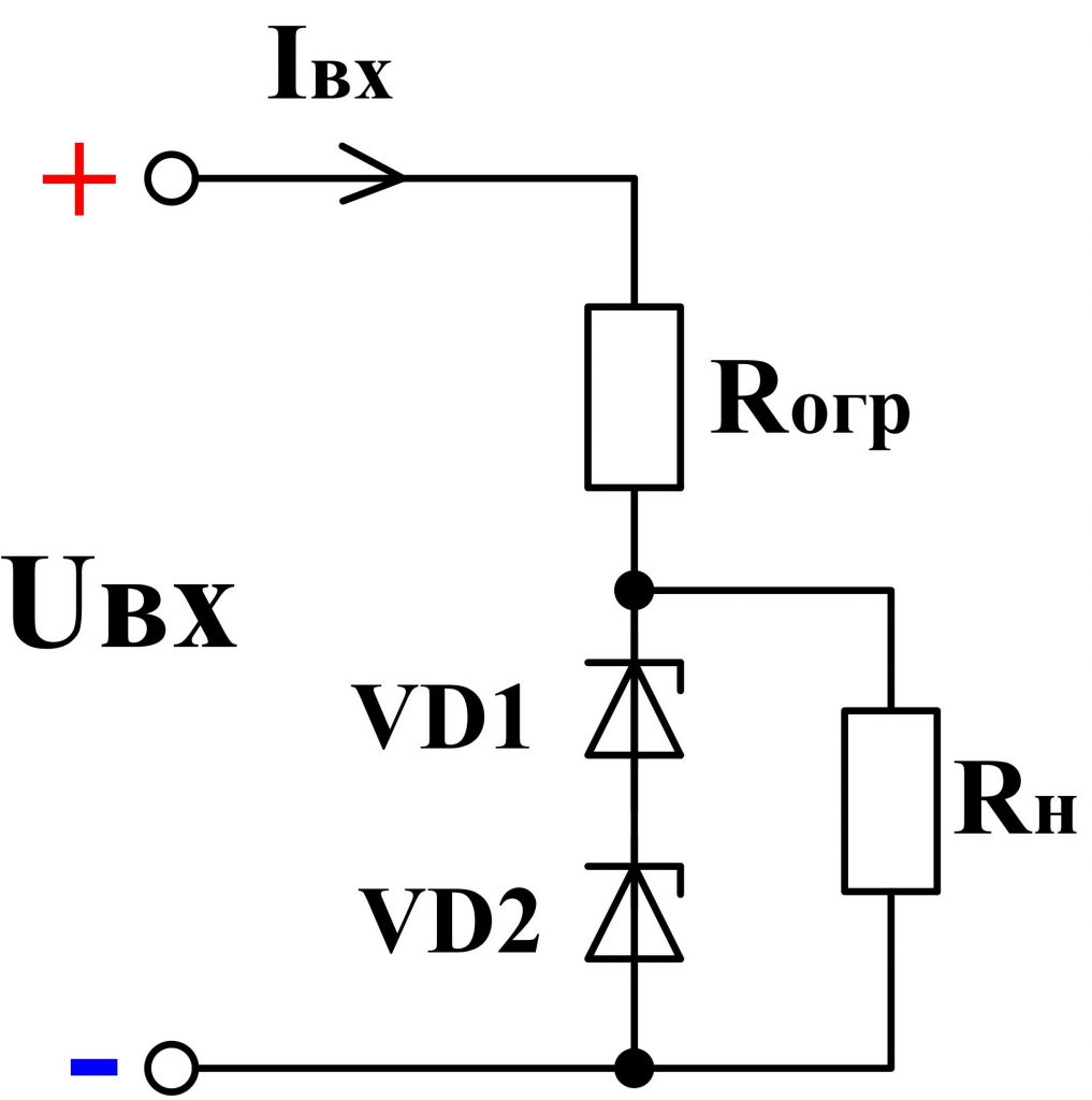
Fig. 6 - Serial connection of zener diodes
Also zener diodes are successfully used in automation systems as sensors reacting to voltage changes. For example, if the voltage exceeds a certain value, the zener diode opens and a current flows through the relay coil. As a result, the relay will work and give a command to other devices or simply signal about exceeding a certain voltage level.
In addition to stabilizing the DC voltage, stabilizers can also stabilize the AC voltage. To do this, use consecutive counter the inclusion of two zener diodes ( fig. 7th ).
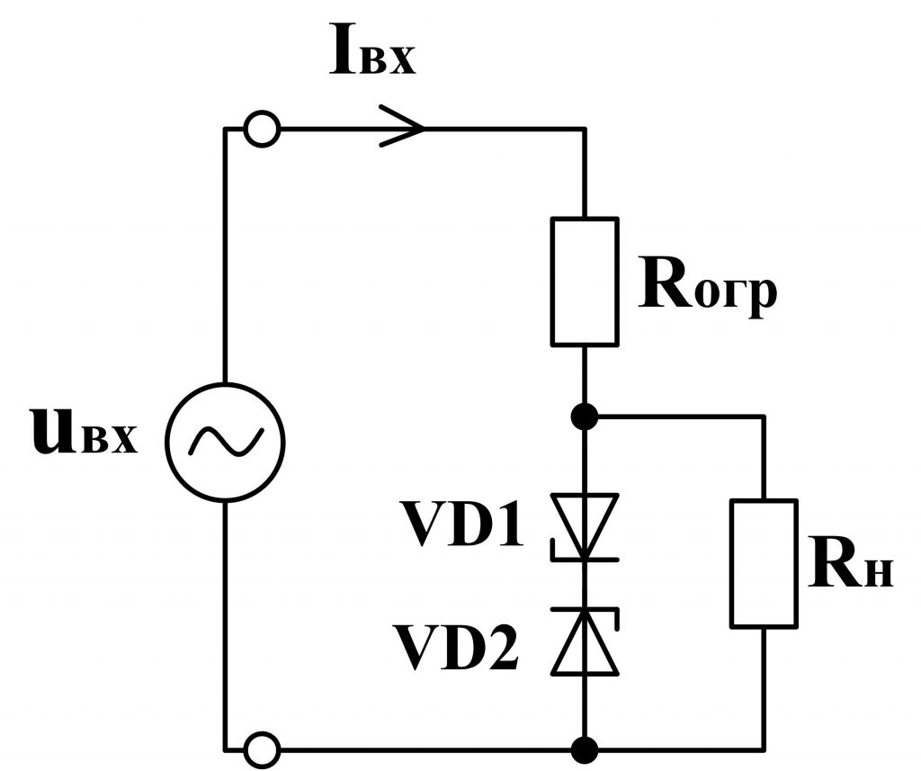
Fig. 7 - Scheme of zener diode on alternating voltage
Only the output will not be an ideal sine wave, but with cut off tops, i.e. the shape of the voltage will be approximated to the trapezium ( fig. 8, 9 ).
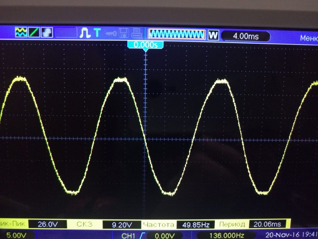
Fig. 8 - Oscillogram of the input voltage
![]()
Fig. 9 - Voltage oscillogram on the zener diode
Used several ways of marking zener diodes. Zener diodes in the glass case, having flexible terminals, are marked in the most understandable way. As a rule, figures are placed on the body, separated by the Latin letter "V". For example, 4 V 7 means that the stabilization voltage is 4.7 V; 9 V 1 - 9.1 V and so on ( fig. 10 ).
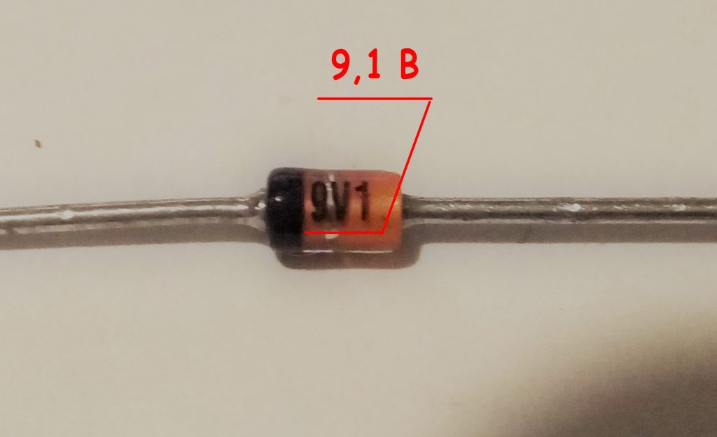
Fig. 10 - Marking of zener diodes in glass housings
Zener in the plastic case are marked in the form of numbers and letters. In themselves, these figures do not say anything, however, with the help of dashshit they can be easily decoded. For example, the designation 1N5349B means that the stabilization voltage is 12 V ( fig. eleven). In addition to voltage, this marking takes into account other parameters of the zener diode.
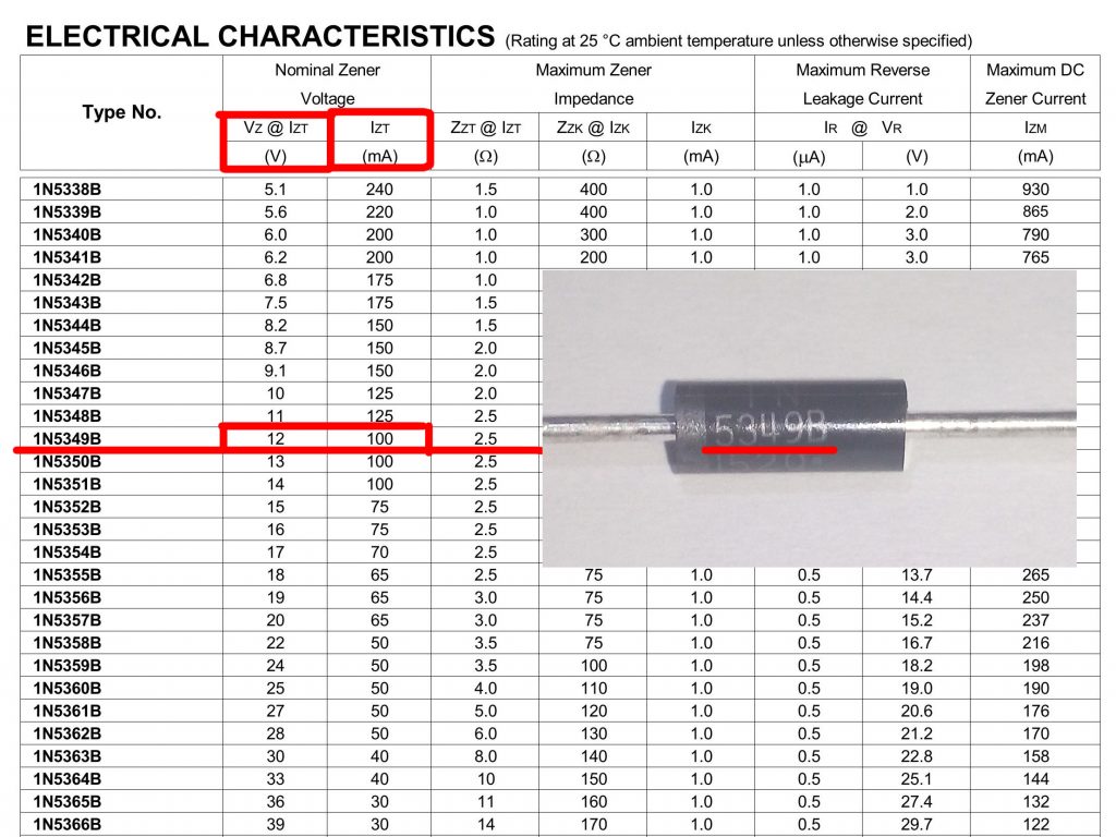
Fig. 10 - Marking of zener diodes in plastic housings
A black or gray ring applied to a zener diode body designates its cathode ( fig. 12 ).
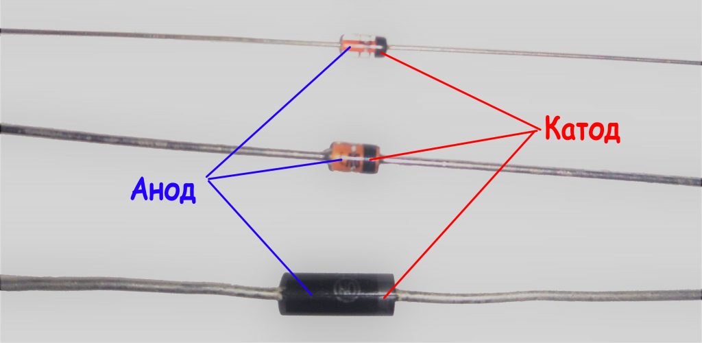
Fig. 12 -
Markingsmd zener diodes
As a marking of smd zener diodes, color rings are used. Similar markings are also applied for Soviet not smd zener diodes. In imported zener diodes, a colored ring is applied from the cathode side ( fig. 13 ). To decode colored rings, use dataschi or online decryption.
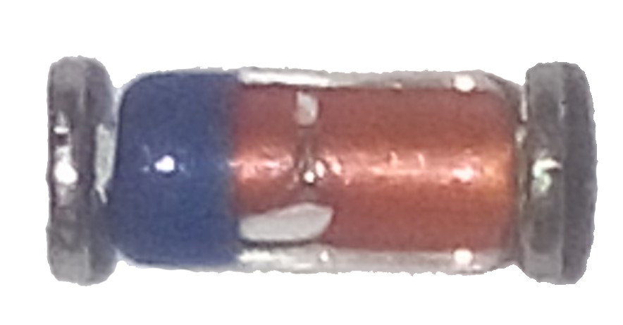
Fig. 13 -SMD zener diode in glass case
Smd zener diodes with three pins are also manufactured ( fig. 14 ). One of them is not involved. These conclusions can be determined using a multimeter.
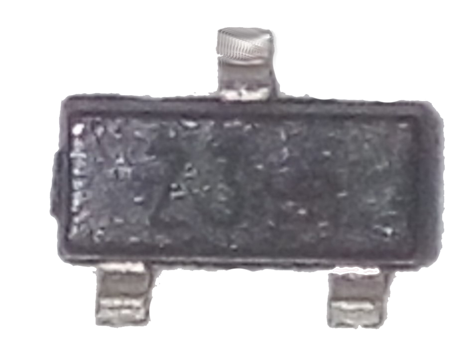
Fig. 14 - SMD zener diode with three leads
In the absence of a directory, a datasheet or fuzzy marking, the nominal voltage of a zener diode can be determined empirically. First, using a multimeter, you need to find out the corresponding conclusions and connect the zener diode via a current-limiting resistor ( see Fig. 5). Then apply voltage from the regulated power source. Smoothly changing the input voltage, you need to monitor the voltage change on the zener diode. If the voltage on the zener diode does not change when the voltage of the power supply changes, then this will be its stabilization voltage.
The conclusions of the zener diode are determined exactly as and. The multimeter should be set to the continuity mode and the probes should be touched by the probes ( fig. 15, 16 ).
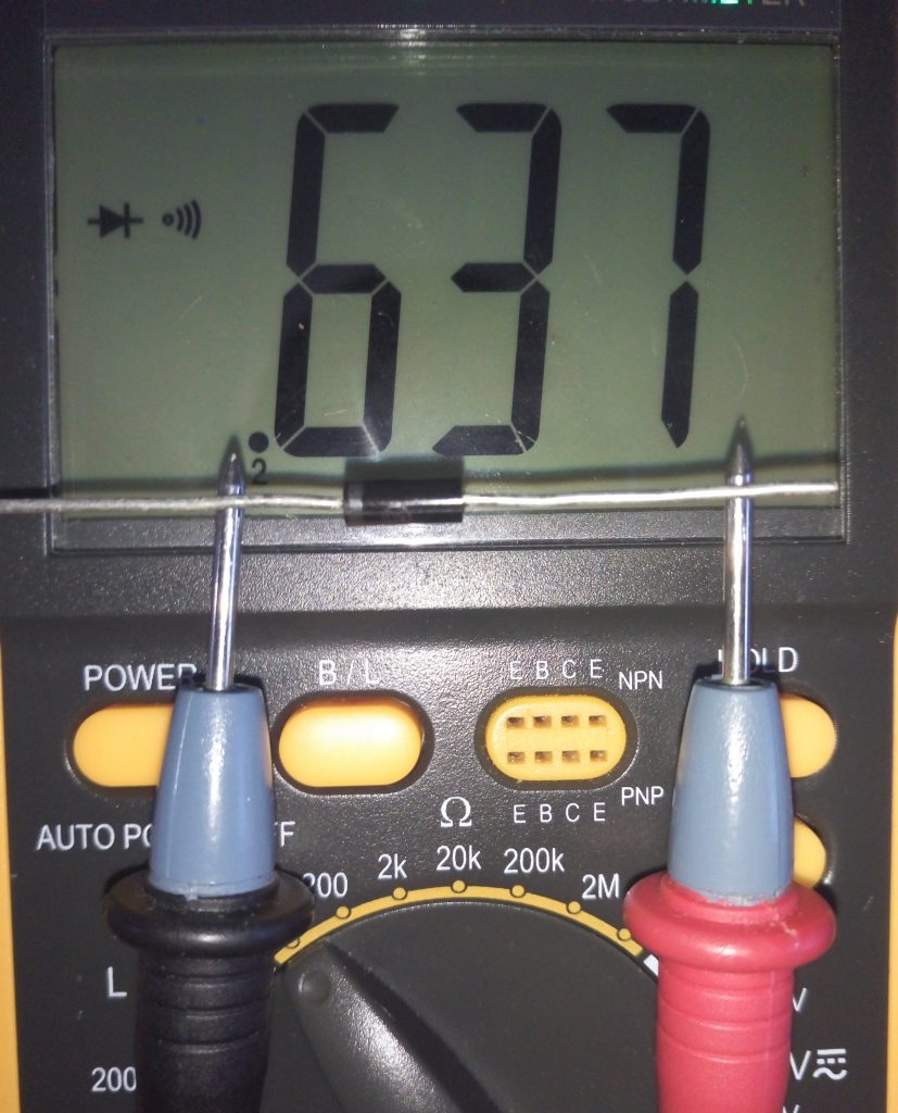
Fig. 15 - Direct voltage
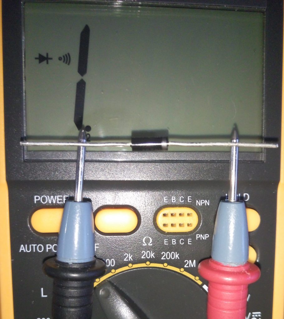
Fig. 16 - Reverse voltage
Under the action of a flowing current through the zener diode, it heats up. The released heat dissipates into the surrounding space. The more zener diode is able to dissipate heat without overheating, the higher its dissipation power and the more current can be passed through it. As a rule, the larger the zener diode dimensions, the greater its scattering power ( fig. 17th ).
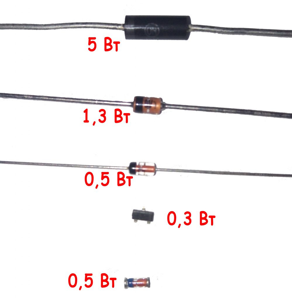
Fig. 17 - Power dissipation of zener diodes
Having a radio-electronic laboratory at home, you can make a variety of devices for your electrical equipment or the instruments yourself, which will save considerable money on the purchase of equipment. An important element of many electrical circuits devices is a zener diode.
Such an element (smd, cmd) is a necessary part of many electrical circuits. Due to its wide field of application, the zener diode has a different marking. The marking applied to the body of such a diode gives detailed but encrypted information about this element. Our today's article will help you to understand which color marking meets on the body (glass and no) of imported zener diodes.
What is this element of electrical circuits
Before we start to consider the question of what color marking of such elements exists, it is necessary to understand what it is all about.
Volt-ampere characteristic of a zener diode
The Zener is a semiconductor diode, which is intended to stabilize the DC voltage in the circuit on the load. Most often, such a diode is used to stabilize the voltage in various power supplies. This diode (smd) has a section with a reverse branch of the current-voltage characteristic, which is observed in the region of electric breakdown.
Having such a region, a zener diode in the situation of changing the current parameter flowing through the diode from ITS.MIN to ITS.MAKS practically no changes in the voltage index are observed. This effect is used to stabilize the voltage. In a situation where the RH load is connected in parallel to the cmd, then the diode voltage will remain constant, and within the specified limits the current flowing through the zener diode.
Note! Stabilitron (smd) is able to stabilize the voltage above 3.3 V.
In addition to CMD, there are also stability vectors that are included when direct inclusion. They are used in situations where there is a need to stabilize the voltage in a certain range. A conventional diode can be used when it is necessary to stabilize the voltage in the range from 0.3 to 0.5 V. The region of their direct displacement is observed when the voltage drops to 0.7-2v. In this case, it is practically independent of the current. Stabistors in their work apply a straight branch of the current-voltage characteristic.
They should also be included when direct connection. Although this will not be the best solution, since a zener diode in such a situation will still be more effective.
Stabistors, like smd, are often made from silicon.
The zener diodes are labeled according to their main characteristics. This marking has the following form:
- UDC. This marking means the nominal voltage for stabilization;
- ΔUst. Indicates deviation of the voltage indicator of the nominal stabilization voltage;
- Ist. Indicates a current that flows through the diode at a nominal stabilizing voltage;
- Ist.min - the minimum value of the current that flows through the zener diode. With this value, such an smd diode will have a voltage in the range UST ± ΔUST;
- Ist.MAX. Means the maximum permissible value of the current that can flow through the zener diode.
This marking is important when selecting an element for a specific wiring diagram.
Element designation
![]()
Schematic designation of a zener diode
Since the zener diode is a special diode, its designation does not differ from them. Schematically, smd is denoted as follows:
The zener diode, like the diode, has a cathode and anodic part in its composition. Because of this, there is a direct and reverse inclusion of this element.
Turning on the Zener diode
At first glance, the inclusion of such a diode is wrong, because it must be connected "on the contrary." In the situation of supplying reverse voltage to smd, the phenomenon of "breakdown" is observed. As a result, the voltage between its terminals remains unchanged. Therefore, it must be connected in series to the resistor in order to limit the current flowing through it, which will ensure the drop of the "excess" voltage from the rectifier.
Note! Each diode, designed to stabilize the voltage, has its voltage "breakdown" (stabilization), and also has its working current.
Due to the fact that each zener diode has such characteristics, it is possible to calculate the resistor value for it, which will be connected with it in series. For imported zener diodes, their stabilization voltage is represented in the form of a marking applied on the body (glass or not). The designation of such a smd diode always starts with BZY ... or BZX ..., and their breakdown voltage (stabilization) is marked V. For example, the designation 3V9 stands for 3.9 volts.
Note! The minimum voltage for stabilization of such elements is 2 V.
The principle of stabilization diodes
Despite the fact that the CMD is similar to a diode, it is in fact a different element of the electrical circuit. Of course, it can perform the function of a rectifier, but it is usually used to stabilize the voltage. This element is able to support in the circuit direct current constant pressure. This principle of its work is used in the supply of various radio equipment.
Externally, the CMD is very similar to the standard semiconductor. Similarity is preserved in structural features. But in the designation of such a radio-technical element, unlike a diode, the diagram puts the letter G.
If you do not delve into mathematical calculations and physical phenomena, then the principle of the functioning of smd will be fairly clear.
Note! When switching on such an smd diode, observe the reverse polarity. This means that the connection is made by the anode to the minus.
Passing through this element, a small voltage of the circuit provokes a strong current. With increasing reverse voltage, the current also increases, only in this case its growth will be observed weakly. Going to the mark, it can be any. It all depends on the type of device. When the mark is reached, a "breakdown" occurs. After the "breakdown" happened, a reverse current of large value begins to flow through smd. It is at this moment that the element begins to work until its permissible limit is exceeded.
How to distinguish a stabilization diode from a conventional semiconductor
Very often people ask how it is possible to distinguish a zener diode from a standard semiconductor, because, as we found out before, both these elements have almost identical designations on the electrical circuit and can perform similar functions.
The most simple way The difference between the stabilization semiconductor and the conventional one is the use of the preamplifier circuit to the multimeter. With its help it is possible not only to distinguish both elements from each other, but also to reveal the stabilization voltage, which is characteristic for a given cm (if it, of course, does not exceed 35V).
The circuit of the multimeter is a DC-DC converter, in which there is galvanic isolation between the input and output. This scheme has the following form:
![]()
The circuit of a prefix of a multimeter
The generator with pulse-width modulation is performed on a special microcircuit MC34063, and to create a galvanic isolation between the measuring part of the circuit and the power supply, the control voltage should be removed from the primary winding of the transformer. For this purpose, there is a rectifier on VD2. In this case, the value for the output voltage or the stabilizing current is set by selecting the resistor R3. On the capacitor C4, a voltage of about 40V is produced.
In this case, the tested VDX cm and the stabilizer for current A2 will form a parametric stabilizer. The multimeter connected to terminals X1 and X2 will measure the voltage on the zener diode.
When the cathode is connected to the "-" and the anode to the "+" diode, as well as to the asymmetrical cmd of the multimeter, the latter will show a slight voltage. If connected in reverse polarity (as in the diagram), then in the situation with a conventional semiconductor device will record a voltage of about 40V.
Note! For a symmetrical smd, the breakdown voltage will appear if there is any polarity of the connection.
Here, the transformer T1 will be wound on a torus-shaped ferrite core with an outer diameter of 23 mm. Such a winding 1 will contain 20 turns, and the second winding will have 35 turns of a PEV wire of 0.43. It is important when winding lay the turn to the turn. It should be remembered that the primary winding goes on one part of the ring, and the second - on the other.
When setting up the device, connect a resistor instead of smd VDX. This resistor must have a rating of 10 kΩ. And the resistance R3 should be selected in order to achieve a voltage of 40V on the capacitor C4
That's how you can find out whether you have a zener diode or an ordinary diode.
Details about the color marking of the stabilizing diode
Any diode (zener diode, etc.) on its body contains a special marking, which reflects what material was used to make each specific semiconductor. Such a marking can have the following form:
- letter or number;
- letter.
In addition, the marking reflects the electrical properties and purpose of the device. Usually the figure answers for this. The letter, in turn, reflects the corresponding version of the device. In addition, the marking contains the date of manufacture and the symbol of the product.
ICDs of the integral type often contain a complete marking. In this situation, there is a conditional code on the case of the product, which indicates the type of the chip. An example of decoding of the code marking on the case for microcircuits is shown in the figure:
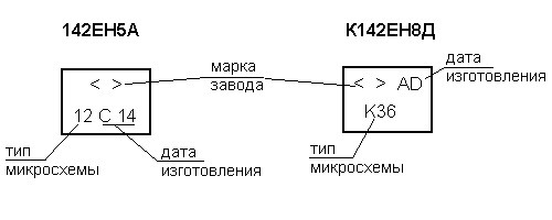
Example of chip labeling
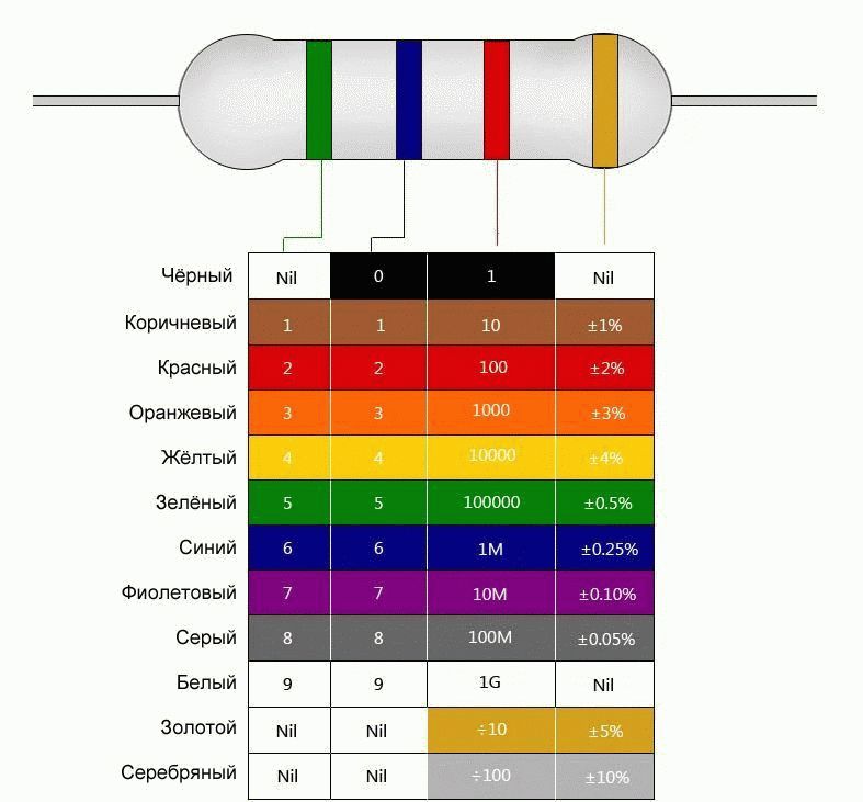
In addition, there is also a color marking. It exists in several variants, but the most commonly used is the Japanese marking (JIS-C-7012). Color markings are shown in the following table.
Color marking of the zener diode
- the first bar indicates the type of device;
- the second is a semiconductor;
- the third - what kind of device is it, and also what conductivity it has;
- the fourth is the development number;
- the fifth is the modification of the device.
It should be noted that the fourth and fifth strips are not very important for product selection.
Conclusion
As you can see, there are a lot of different markings and designations for the zener diode, which you need to remember when choosing it for a home laboratory and manufacturing your own electrical appliances. If you are good at this issue, then this is the key to the right choice.
How to choose a motion sensor for the toilet How to choose the right radio light switch with a remote control, how to connect