Antipyretics for children are prescribed by a pediatrician. But there are situations of emergency care for fever, when the child needs to give the medicine immediately. Then the parents take responsibility and apply antipyretic drugs. What is allowed to give to infants? How can you bring down the temperature in older children? Which medications are the safest?
Often the focus is on the study of three-phase electric motors, in part because three-phase motors are used more often than single-phase motors. Single-phase motors have the same operating principle as three-phase motors, only with lower starting torque. They are subdivided by type depending on the way of starting.
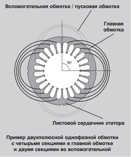
Standard single-phase stator has two windings, located at an angle of 90 ° with respect to each other. One of them is considered the main winding, the other - auxiliary, or starting. In accordance with the number of poles, each winding can not be divided into several sections.
The figure shows an example of a bipolar single-phase winding with four sections in the main winding and two sections in the auxiliary winding.
It should be remembered that the use of a single-phase electric motor is always a kind of compromise. The design of a particular engine depends, first of all, on the task. This means that all motors are designed in accordance with what is most important in each case: for example, efficiency, torque, duty cycle, etc. Due to the pulsating field, single-phase CSIR and RSIR motors can have a higher noise level than the two-phase PSC and CSCR motors, which work much quieter, because they use a starting capacitor. Condenser, through which the motor is started, contributes to its smooth operation.
Basic types of single-phase induction motors
Household appliances and low-power devices operate from single-phase alternating current, in addition, not all three-phase power supply can be provided. Therefore single-phase AC motors have become widespread, especially in the USA. Very often AC motors are preferred because they are distinguished by their robust design, low cost, and they do not require maintenance.
As the name suggests, a single-phase induction motor works by the principle of induction; The same principle applies to three-phase electric motors. However, there are differences between them: single-phase electric motors, as a rule, operate with alternating current and voltage of 110 -240 V, the stator field of these motors does not rotate. Instead, each time a sinusoidal voltage jumps from negative to positive, poles change.
AT single-phase electric motors The stator field is constantly aligned in one direction, and the poles change their position once in each cycle. This means that a single-phase induction motor can not be started independently.

Theoretically, a single-phase electric motor could be started by mechanical rotation of the motor with the subsequent immediate connection of power. However, in practice, all electric motors are started automatically.
There are four main types of electric motors:
Induction motor with capacitor start / work through winding (inductance) (CSIR),
Induction motor with capacitor start / capacitor operation (CSCR),
Induction motor with rheostatic start (RSIR) and
A motor with a constant capacity separation (PSC).
The following figure shows the typical torque / speed relationship curves for the four main types of single-phase AC motors.
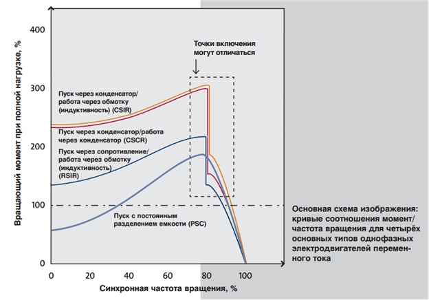
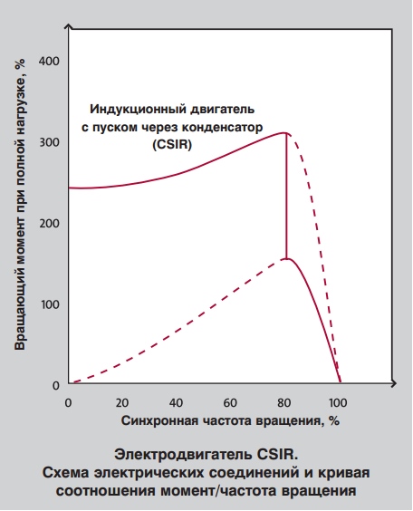
Single-phase electric motor with starting through a capacitor / working through a winding (CSIR)
Induction motors with capacitor start-up, also known as CSIR motors, constitute the largest group of single-phase motors.
CSIR engines are presented in several sizes: from the lowest power to 1.1 kW. In CSIR motors, the capacitor is connected in series with the starting winding. The capacitor causes some lag between the current in the starting winding and in the main winding.
![]()
This helps to delay the magnetization of the starting winding, which leads to the appearance of a rotating field, which affects the occurrence of torque. After the motor has reached the speed and approaches the operating speed, the starter opens. Then the electric motor will operate in the usual mode for the induction motor. The starter can be centrifugal or electronic.
CSIR motors have a relatively high starting torque, ranging from 50 to 250 percent of torque at full load. Therefore, of all single-phase motors, these motors are best suited for situations where starting loads are high, for example for conveyors, air compressors and refrigeration compressors.
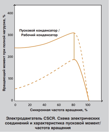
Single-phase electric motor with capacitor start / capacitor operation (CSCR)
This type of motors, which are briefly called "CSCR motors," combines the best properties of an induction motor with a capacitor start and a motor with a permanently connected capacitor. Despite the fact that, because of their design, these motors are somewhat more expensive than other single-phase motors, they remain the best option for use in difficult conditions. The starting capacitor of the motor CSCR is connected in series with the starting winding, as in the electric motor with the start through the capacitor. This provides a high starting torque.
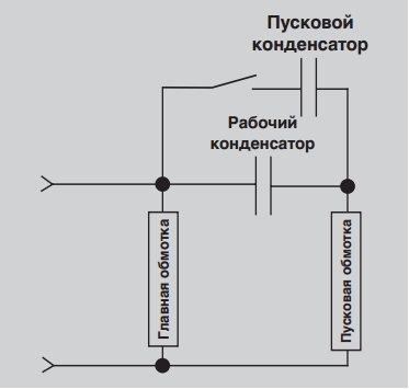
CSCR motors also resemble PSC motors, since they also start through a capacitor that is connected in series with the starting coil if the starting capacitor is disconnected from the mains. This means that the engine copes with maximum load or overload.
CSCR motors can be used to operate with a low full-load current and at a higher efficiency. This gives some advantages, including the ability to run the engine with lower temperature fluctuations, compared to other similar single-phase motors.
CSCR motors are the most powerful single-phase electric motors that can be used in difficult conditions, such as pumps for high-pressure water pumping and vacuum pumps, as well as in other high-torque processes. The output power of such electric motors lies in the range from 1.1 to 11 kW.
Single-phase electric motor with resistance / operation via winding (inductance) (RSIR)
This type of engine is also known as "split-phase motors". They are usually cheaper than single-phase electric motors of other types used in industry, but they also have some performance limitations.
The starting device of the electric motors RSIR includes two separate stator windings. One of them is used exclusively for start-up, the diameter of the wire of this winding is smaller, and the electrical resistance is higher than that of the main windings. This causes the rotation of the rotating field to lag, which, in turn, drives the motor. A centrifugal or electronic starter disconnects the starting coil when the engine speed reaches approximately 75% of the nominal value. After that, the motor will continue to operate in accordance with the standard operating principles of the induction motor.

As already mentioned before, there are some limitations for RSIR electric motors. They have low starting moments, often in the range of 50 to 150 percent of the rated load. In addition, the motor generates high starting currents, approximately 700 to 1000% of the rated current. As a result, a long start-up time will cause overheating and destruction of the starting winding. This means that motors of this type can not be used where large starting moments are required.
The RSIR motors are designed for a narrow voltage range, which naturally limits their application. Their maximum torque varies between 100 and 250% of the calculated value. It should also be noted that an additional difficulty is the installation of thermal protection, since it is difficult to find a protective device that would operate quickly enough to prevent the starting winding from burning out. RSIR motors are suitable for use in small chopping and milling devices, fans, as well as for applications in other areas where a low starting torque and the required output power on the shaft from 0.06 kW to 0.25 kW are permissible. They are not used where there should be high torque or long cycles.

Single-phase electric motor with constant capacitance separation (PSC)
As can be seen from the name, the engines with a constant capacitance separation (PSC) are equipped with a capacitor which, during operation, is constantly switched on and connected in series with the starting winding. This means that these motors do not have a starter or a capacitor, which is only used for starting. In this way, starting winding becomes an auxiliary winding when the motor reaches the operating speed.

The design of PSC motors is such that they can not provide the same starting torque as electric motors with starting capacitors. Their starting moments are rather low: 30-90% of the rated load, so they are not used in systems with a large starting load. This is compensated for by low starting currents - usually less than 200% of the rated load current - which makes them the most suitable motors for applications with a long duty cycle.
Motors with constant capacity separation have a number of advantages. The operating parameters and the speed of rotation of such motors can be selected in accordance with the tasks assigned, in addition, they can be manufactured for optimum efficiency and a high power factor at rated load. Since they do not require a special start-up device, they can easily be reversed (reverse the direction of rotation). In addition to all of the above, they are the most reliable of all single-phase electric motors. That's why Grundfos uses single-phase PSC motors in standard design for all applications with capacities up to 2.2 kW (2-pole) or 1.5 kW (4-pole).
Motors with constant capacity separation can be used to perform a number of different tasks depending on their design. A typical example are low inertia loads, such as fans and pumps.

Two-wire single-phase electric motors
Two-wire single-phase motors have two main windings, a starting winding and a working capacitor. They are widely used in the US with single-phase power supplies: 1 ½ 115 V / 60 Hz or 1 ½ 230 V / 60 Hz. When the correct connection this type of electric motor can be used for both types of power supply.

Limitations of single-phase electric motors
In contrast to the three-phase for single-phase electric motors, there are some limitations. Single-phase motors must never run idle, as they are very hot under low loads, it is also recommended to operate the engine at a load of less than 25% of the full load.
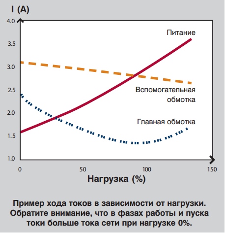
The PSC and CSCR motors have a symmetrical / circular rotating field at one point of the load application; this means that at all other points of the load application the rotating field is asymmetric / elliptical. When the motor is operated with an asymmetric rotating field, the current in one or both windings can exceed the current in the network. Such excess currents cause losses, so one or both windings (which often occurs when there is no load at all) are heated, even if the current in the network is relatively small. See the examples.

On the voltage in single-phase electric motors
It is important to remember that the voltage at the starting winding of the motor can be higher than the mains supply voltage of the motor. This also applies to the symmetrical mode of operation. See the example.

Changing the supply voltage
It should be noted that single-phase motors are usually not used for large voltage ranges, in contrast to three-phase motors. In this regard, there may be a need for engines that can work with other types of voltage. To do this, some structural changes must be made, for example, additional winding and capacitors of different capacities are needed. Theoretically, the capacitance of a capacitor for a different mains voltage (with the same frequency) should be equal to the square of the ratio of the voltages:
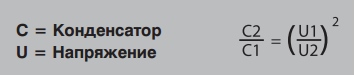
Thus, in a motor designed for 230 V power supply, a 25μF / 400 V capacitor is used, for a 115 V motor model, a capacitor of 100μF with a marking of more than low voltage for example 200 V.
Sometimes we choose capacitors of smaller capacity, for example 60μF. They are cheaper and take up less space. In such cases, the winding must be suitable for a certain capacitor. It should be taken into account that the electric motor performance will be less than with a capacitor of 100μF capacity - for example, the starting torque will be lower.
Conclusion
Single-phase electric motors operate on the same principle as three-phase motors. However, they have lower starting moments and voltage values (110-240 V).
Single-phase motors must not run idle, many of them must not be operated at a load less than 25% of the maximum, as this causes a temperature rise inside the motor, which can lead to its breakdown.
Hello, dear readers and guests of the site "Notes electrician."
I am often asked how it is possible to distinguish a working winding from a starting one in single-phase motors when there is no marking on the wires.
Each time you have to explain in detail what and how. And today I decided to write about this whole article.
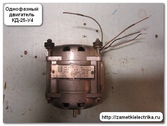
As an example, I'll take a single-phase electric motor KD-25-U4, 220 (V), 1350 (rpm):
- KD - capacitor motor
- 25 - power 25 (W)
- У4 - climatic performance
Here is its appearance.


As you can see, there is no marking (color and digital) on the wires. On the engine tag, you can see what kind of markings the wires should have:
- working (С1-С2) - wires of red color
- starting (B1-B2) - wires of blue color
![]()
First of all, I will show you how to determine the working and starting windings single-phase motor, and then I will collect the scheme of its inclusion. But this will be the next article. Before I begin reading this article, I recommend that you read: connection of single-phase capacitor motor.
So, let's get started.
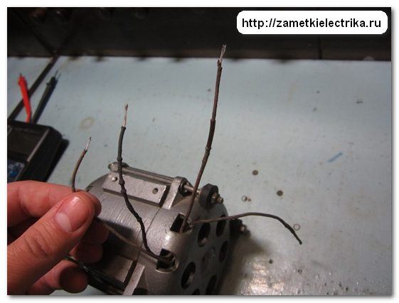
1. Wire cross-section
Visually look the cross section of conductors. A pair of wires, in which the cross section is larger, refer to the working winding. And vice versa. Wires, in which the cross section is less, refer to the starting wire.

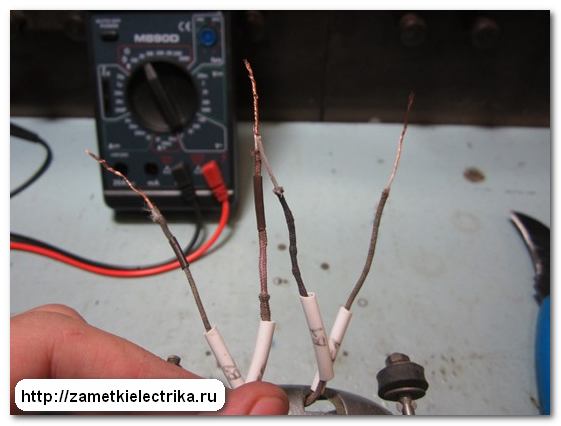
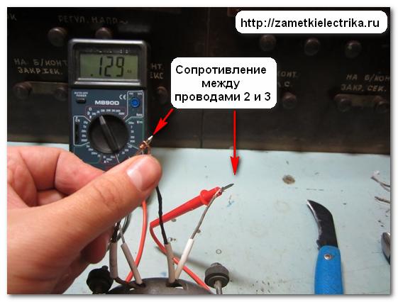
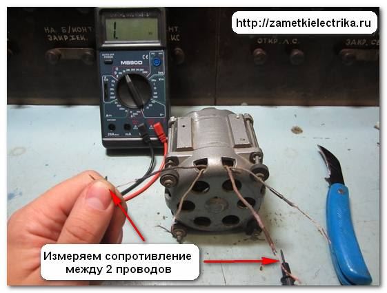
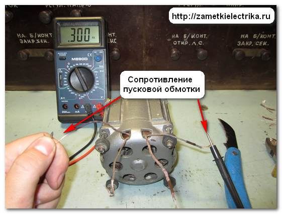
Then we take the probes of the multimeter and we measure the resistance between any two wires.
![]()
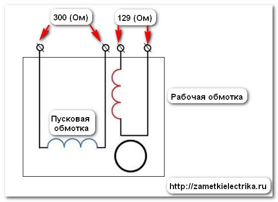
If there is no indication on the display, then you need to take another wire and again take a measurement. The measured resistance value is now 300 (Ω).

We found the conclusions of one winding. Now we connect the multimeter probes to the remaining pair of wires and measure the second winding. It was 129 (Om).

We draw a conclusion: The first winding - starting, the second - working.
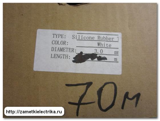
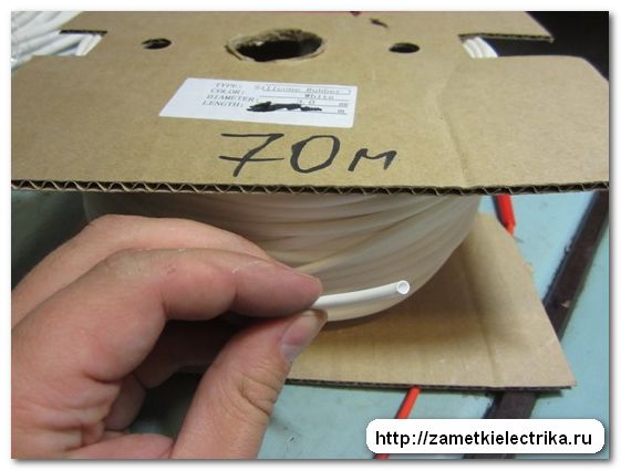
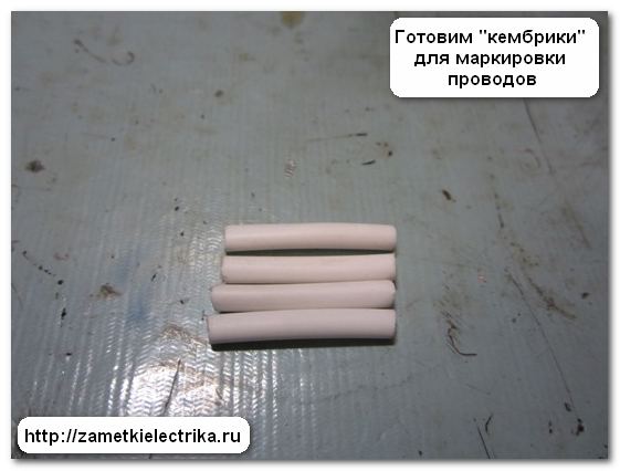
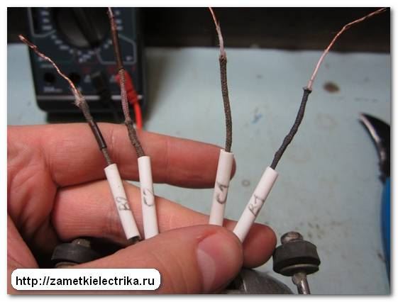
To avoid further entanglement in the wires when the engine is connected, prepare the beads ("cambric") for marking. Usually, as a tag I use, or an isolation pVC tube, or a silicon tube (Silicone Rubber) of the diameter I need. In this example, I applied a silicone tube with a diameter of 3 (mm).
According to the new GOSTs, single-phase motor windings are designated as follows:
- (U1-U2) - working
- (Z1-Z2) - starting
At the engine KD-25-U4, taken as an example, the digital marking is done still in the old way:
- (С1-С2) - working
- (В1-В2) - starting
That there were no inconsistencies of marking of wires and the scheme shown on a label of the engine, I left the marking old.
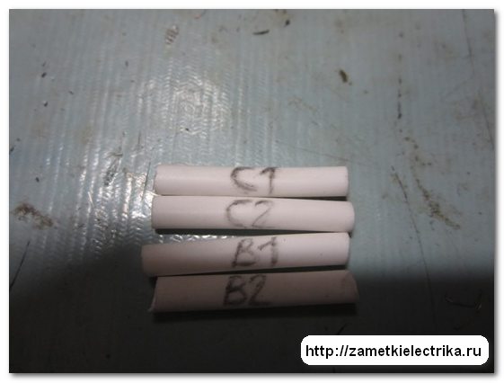

I put tags on the wires. That's what happened.


For reference: Many are mistaken when they say that the rotation of the engine can be changed by changing the power plug (changing the poles of the supply voltage). It is not right!!! To change the direction of rotation, you need to swap the ends of the starting or working windings. The only way!!!
We have considered the case where 4 wires are output to the terminal block of a single-phase motor. And it happens that there are only 3 wires in the terminal block.
In this case, the working and starting windings are connected not in the motor terminal block, but inside the housing thereof.
How to be in this case?
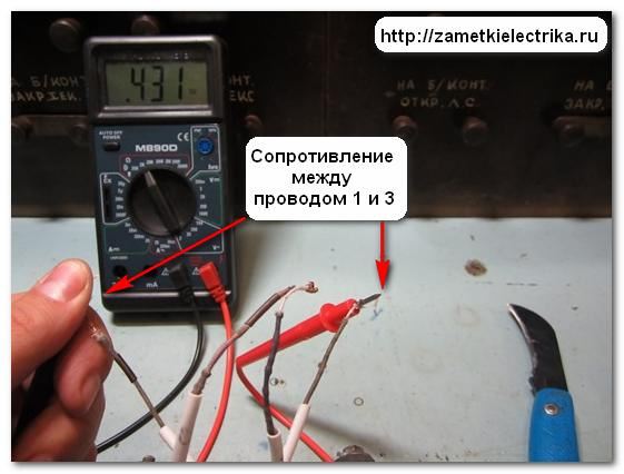
We do everything the same way. We measure the resistance between each wire. We will mentally designate them as 1, 2 and 3.

![]()
Here's what I got:
- (1-2) to 301 (ohms)
- (1-3) to 431 (ohms)
- (2-3) to 129 (ohms)
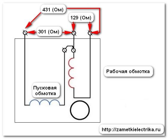
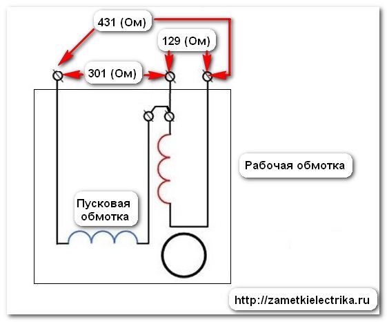
Hence we draw the following conclusion:
- (1-2) - starting winding
- (2-3) - working winding
- (1-3) - starting and working windings are connected in series (301 + 129 = 431 Ohm)
For reference: With this winding connection, the reverse of a single-phase motor is also possible. If you really want to, you can open the motor housing, find the place of connection of the starting and working windings, disconnect this connection and put 4 wires in the terminal block, as in the first case. But if you have a single-phase motor is a capacitor, as in my case with the KD-25, then its
25. SCHEMES OF INCLUSION OF SINGLE-PHASE ASYNCHRONOUS MOTORS
One phase motors On the stator there are two windings: a working winding and an auxiliary winding. The latter is included only for the duration of the launch and is therefore called the starting one. The working winding is also called the main phase, and the starting winding is called the auxiliary phase. Power supply single-phase motors is carried out from a single-phase network.
Widespread are single-phase motors, which consistently include two windings (two phases). Such engines are, according to the principle of operation, two-phase, but since they are included in single-phase network, and in the auxiliary phase of such engines there is usually a permanently connected capacitor, they are called single-phase capacitor motors, in contrast to single-phase motors with a starting winding.
Rotors single-phase motors, including condensers, perform in most cases short-circuited.
The starting winding of a single-phase motor has a high current density, is switched on only for the start-up period and after reaching a speed close to the rated speed, it must be switched off. The time it is under current is limited. So, for example, for micromotors of a single series such as AOLB, AOLG, this time in order to avoid overheating of the winding should not exceed 3 s. Frequent starts can lead to overheating of the starting winding.
For single-row micro motors, three consecutive cold starts and one of a hot run are allowed, provided that the winding takes 3 seconds to start.
The starting winding is switched off by a centrifugal or pushbutton switch, a relay overcurrent, bimetal thermal relay and other devices.
To change the direction of rotation of a single-phase motor, you must switch the outputs of one of the stator phases.
Depending on the type of starting element included in the auxiliary phase, one-phase motors with starting resistance are distinguished (Figures 58, a) and with starting capacity (Figure 58, b).
The starting resistance may be external, i.e., located outside the winding and connected with it in series, or introduced. Motors with auxiliary resistance added to the auxiliary winding are also called motors with increased starting-phase resistance. In this case, the starting winding is usually done with bifilar coils with a wire of reduced cross-section. Motors with starting capacitance or external resistance are called single-phase motors with starting elements.
Single-phase capacitor motors have either two tanks - starting and working (Figure 58, at),or only one - working (Figure 58, g).The starting capacitor is switched on only for the start-up period and serves to increase the starting torque.
In recent years, universal asynchronous micromotors have been produced, designed for operation from both a three-phase and a single-phase network. When included in the three-phase network The phases of the motor winding are switched on by a triangle or a star, depending on the rated voltage of the network. In a single-phase network, the motors are switched on by one of the circuits (Fig. 59). With such schemes, a single-phase network must correspond to a larger rated motor voltage. For example, if the engine has
Fig. 58. Schemes of single-phase asynchronous motors: a - starting resistance, b - starting capacity, c - starting and working capacitors (condenser motor), g - with a working capacitance: A - main winding, B - auxiliary winding, R p - starting resistance, С n-starting capacity, С р - working capacity
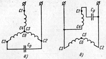
Fig. 59. Schemes for inclusion three-phase winding into a single-phase network: a - when winding is connected to a star with parallel capacitance included, b - when parallel connection main and auxiliary windings
127/220 V, then in single-phase mode it should work at 220 V.
How to determine the working and starting windings of a single-phase electric motor
Hello, dear readers and guests of the site "Notes electrician."
I am often asked how it is possible to distinguish a working winding from a starting one in single-phase motors when there is no marking on the wires.
Each time you have to explain in detail what and how. And today I decided to write about this whole article.
As an example, I'll take a single-phase electric motor KD-25-U4, 220 (V), 1350 (rpm):
- KD - capacitor motor
- 25 - power 25 (W)
- У4 - climatic performance
Here is its appearance.
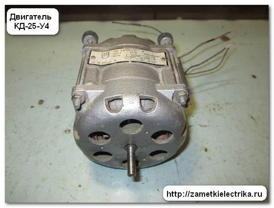

As you can see, there is no marking (color and digital) on the wires. On the engine tag, you can see what kind of markings the wires should have:
- working (С1-С2) - wires of red color
- starting (B1-B2) - wires of blue color
First of all, I will show you how to determine the working and starting windings of a single-phase motor, and then I will assemble a scheme for switching it on. But this will be the next article. Before I begin reading this article, I recommend that you read: the connection of a single-phase capacitor motor.
Visually look the cross section of conductors. A pair of wires, in which the cross section is larger, refer to the working winding. And vice versa. Wires, in which the cross section is less, refer to the starting wire.
Knowing the basics of electrical engineering. we can say with confidence: the larger the cross-section of wires, the lower their resistance, and vice versa, the smaller the cross-section of wires, the greater their resistance.
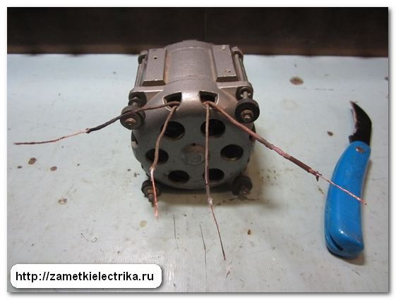
In my example, the difference in the cross-section of the wires is not visible, because they are thin and can not be distinguished by eye.
2 . Measuring ohmic resistance of windings
Even if the difference in the cross-section of the wires is not visible to the armed eye, then I still recommend that you measure the resistance of the windings. Thus, we will at the same time verify their integrity.
To do this, use the digital multimeter M890D. Now I will not tell you how to use a multimeter, read about it here:
Remove the insulation from the wires.
Then we take the probes of the multimeter and we measure the resistance between any two wires.
If there is no indication on the display, then you need to take another wire and again take a measurement. The measured resistance value is now 300 (Ω).
We found the conclusions of one winding. Now we connect the multimeter probes to the remaining pair of wires and measure the second winding. It was 129 (Om).

We draw a conclusion: the first winding - starting, the second - working.

To avoid further entanglement in the wires when the engine is connected, prepare the beads ("cambric") for marking. Usually, as a tag I use, either an insulating PVC pipe or a silicone Rubber tube of the diameter I need. In this example, I applied a silicone tube with a diameter of 3 (mm).


According to the new GOSTs, single-phase motor windings are designated as follows:
At the engine KD-25-U4, taken as an example, the digital marking is done still in the old way:
That there were no inconsistencies of marking of wires and the scheme shown on a label of the engine, I left the marking old.


I put tags on the wires. That's what happened.

For reference: Many are mistaken when they say that the rotation of the motor can be changed by changing the power plug (changing the poles of the supply voltage). It is not right. To change the direction of rotation, you need to swap the ends of the starting or working windings. The only way.
We have considered the case where 4 wires are output to the terminal block of a single-phase motor. And it happens that there are only 3 wires in the terminal block.

In this case, the working and starting windings are connected not in the motor terminal block, but inside the housing thereof.
How to be in this case?
We do everything the same way. We measure the resistance between each wire. We will mentally designate them as 1, 2 and 3.


Here's what I got:
Hence we draw the following conclusion:
- (1-2) - starting winding
- (2-3) - working winding
- (1-3) - starting and working windings are connected in series (301 + 129 = 431 Ohm)
For reference: with such a winding connection, the reverse of a single-phase motor is also possible. If you really want to, you can open the motor housing, find the place of connection of the starting and working windings, disconnect this connection and put 4 wires in the terminal block, as in the first case. But if you have a single-phase motor that is capacitor-like in my case with a KD-25, its reverse can be accomplished by switching the phase of the supply voltage.
P.S. That's all. If there are questions on the material of the article, then ask them in the comments. Thank you for attention.
Good evening, Dmitry! I myself work as an electrician in ETL. I have a question about the tests cable line of crosslinked polyethylene. Have you encountered this, which voltage was applied, what were the leakage currents, how many time passes the test of one phase? Thank you in advance. if you can send your answer to me on
mail.
Artem, hello. About testing of cables from cross-linked polyethylene I wrote in the comments in this article.
hello Dmitry. but could you write a detailed article about oil circuit breakers, (solenoid, contactor, trip coil, its tests, characteristics measurements) and also tests power transformer and its measurement. it is very necessary, there are nuances in the head.
SLV, I planned to write these articles, especially about different types of drives (PE-11, PS-10, PE-21, etc.), about high-voltage oil and vacuum switches installed both in the CSR chambers and on the carriages, but I'm afraid that many visitors to the site will not be interested. Here constantly and I postpone ...
Hello Dmitry!
You all explain very well, thank you very much! Could you clarify what it means in circuit breakers, for example 6kA or 35kA, if they are designed for a single trip current? And why do they have such a difference in price?
Boris, the values of 4.5 (kA), 6 (kA), 10 (kA), etc. mean the electrodynamic resistance of the protection apparatus in case of a short circuit in the network, i.e. Show how the machine is resistant to short circuit. For the house (apartment) is quite enough 4.5 (kA), tk. the lines from the TP to the residential building and from the ASP to the apartments are quite long, they have a large active resistance, which leads to a reduction in short-circuit currents to 0.5-1.5 (kA), and often even less.
i could not make out the whole Internet, I could not make out the whole Internet, I could read the books at work, I can not understand everything. By the way, you could not say that all the same means tangent of the dielectric loss of oil, that's all they say about the work and no one really knows.)
And yet another. Earlier, many connected 3-phase motors to single-phase circuit, but time is gone. Many now buy ready-made single-phase. I had a table of the ratio of engine power to the power of capacitors. And then one friend asked me to connect a three-phase engine in the garage. I did not find the table, I had to pick it up.
So, do not you have such a table. They were in the old textbooks on electrical engineering. If there is, please publish or send to my E-mail.
Yours faithfully, Nikolay.
Nicholas, read here. There is a calculation of the capacity of the working and starting capacitors, depending on the engine power.
Good afternoon! Tell me please on the problem. Single-phase motor with capacitor start. From time to time the engine does not start up, it's buzzing. The capacitor bank is assembled from three MBGP-2 capacitors of 2 mkF 630V. Conders on the tester show full capacity. What is the risk of an increase in the capacitance of capacitors? and what threatens to reduce the voltage of their own from 630V to 450V? Thanks! resistance of windings 50 Ohm starting 20 Ohm working mark of the engine now I do not remember.
Vadim, if the engine is buzzing, then there is no torque. This can happen for the following reasons: either the capacitors have failed (lack or small capacity), or an interturn occurs in one of the motor windings. It's better to start with a simple one and replace the old capacitors with new ones. You do not need to increase the capacity, well, if only a little bit in one direction or another, but instead of 630 (V), you can safely use 450 (V).
Good afternoon. Capacitors show a nominal capacity. find others we had a problem. either a larger or smaller capacity, or an envelope is not suitable. either the price tag is not real and the delivery time. as I understand if I increase from six to almost seven uF, then there will not be any special problems? The engine by condition runs for about fifteen seconds. The problem with start-up is not systematic. how to calculate the interturn? on three-phase asynchronous ones, I know the device. Thank you.
Hello, connoisseurs. What if the direction of rotation of the engine changes unpredictably. But, if I use a winding with a smaller section as working, then everything works fine, and when changing contacts, it changes the direction of rotation correctly, and it works for about an hour without overheating. old USSR. One winding is 14 Ohms, the second is 56 Ohms.
Kind time of the day, today I started to run the household hood over the stove, the engine speed control unit has long ordered to live long ... ... with the light there are no problems, but with the electric motor there are four wires, how to be with them. Whom where to connect? The all-touch buttons yanked out, put the latched, KRONA GALA hood with three fan speeds ... .Help with the connection.
And how did you determine that the starting winding should have more resistance than the working winding? Based on what? Explain please
Hello, I have the engine 2DAK71-40-1.0-y2 there are four wires (black, red, gray, white), they all ring up among themselves, tell me please how to podkjuchit?
http://zametkielectrika.ru
For illumination and general household purposes in homes, offices, shops, as well as in small industries, a single-phase power supply system along with a three-phase system is widely used. A single-phase system is used where the power consumption is low, where there is no need to use three-phase electrical circuits, where there is no permanent 24-hour power consumption.

Single-phase motors are simple in design and operation, which in turn provides savings in their operation, repair and maintenance in comparison with similar three-phase motors. Usually in household appliances, such as vacuum cleaners, fans, washing machines, hair dryers, centrifugal pumps, small toys, etc. Single-phase electrical machines are used.
Single-phase asynchronous motors are classified as follows:
- Single-phase asynchronous motors or asynchronous motors.
- Single-phase synchronous motors.
- Collector engines.
This article gives the basic idea of a single-phase asynchronous motor, its description and the principle of its operation.
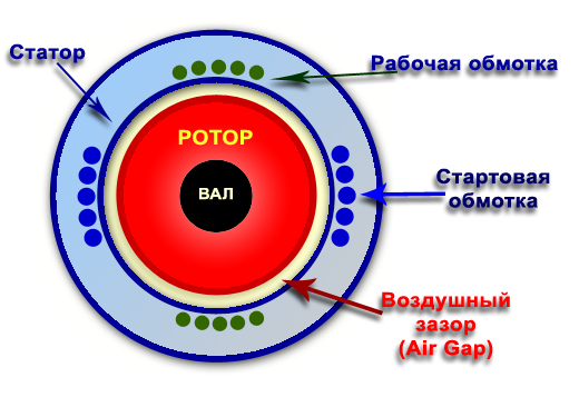
Single-phase induction motor design
Like any other electrical engine, single-phase asynchronous motor consists of two main parts, namely from the rotor and stator. The stator is a fixed part of the engine, and the rotor is a movable part. A single-phase voltage supply is supplied to the stator of an asynchronous motor, which contains windings to create magnetic field. The rotor is a rotating part that is connected to a mechanical load. The rotor of a single-phase asynchronous motor is short-circuited, i.e. it contains a short-circuited winding, usually in its form resembling a squirrel cage (wheel).
The design of a single-phase asynchronous motor is almost the same as design three-phase electric motor with a squirrel-cage rotor. The only difference is the presence of two windings for one phase of the power supply, while in a three-phase motor there is one winding per phase.
Stator of single-phase asynchronous motor
The stator of a single-phase asynchronous motor is made of laminated stamped sheets of electrical steel. Each sheet is isolated from the previous one and then a layer of varnish or other insulating non-magnetic coating. The manufacture of a stator from many thin plates is caused by the need to get rid of the effect of eddy currents. The more plates and the thinner they are, the smaller eddy currents are induced in the stator, which positively affects the conversion efficiency electric power in mechanical energy. In the event that the stator is made of a single piece of electrical steel or other ferromagnetic material, a significant amount of electrical energy will be spent on heating the stator, and this will reduce the efficiency of the engine and can destroy the insulation of the stator windings.
The assembled stator pack contains slots (grooves) for laying windings in them, thus, it turns out that the stator is a magnetic core like a transformer core, and the stator winding is similar to the primary winding of the transformer. Where is the secondary winding located? This needs to be understood. The second winding is short-circuited and it is located on the rotor, and the magnetic coupling between the stator and the rotor is carried out through the air gap.
When power is applied to the stator winding, a magnetic field is created that rotates the rotor at a speed slightly less than synchronous speed N S(rpm = rpm). This speed is determined by the formula:

The stator design of a single-phase motor is similar to the design three-phase motor, with the exception of stator windings:
- First, single-phase asynchronous motors contain mainly concentric windings, since the number of turns of the winding can be easily adjusted, then the magnetomotive force (MMF) (MMF) is distributed almost sinusoidally.
- The motor poles are shifted, except when the induction motor has two stator windings, the main and auxiliary windings. These two windings are located in the stator space at right angles to each other.
Rotor of single-phase asynchronous motor
The design of the rotor of a single-phase asynchronous motor is similar to the short-circuited rotor of a three-phase asynchronous motor. The rotor has a cylindrical shape and slits along the entire periphery. The grooves are made not parallel to the axis of rotation of the rotor, but with a bevel. This tilting prevents the magnetic locking of the rotor in the stator field, thereby facilitating the initial start-up of the engine. Start-up and operation of the asynchronous motor becomes smoother and more relaxed, without excessive overloads at the start and at work.
The winding of the rotor in the form of a squirrel cage consists of aluminum, copper or brass rods, which are located in the grooves on the periphery of the rotor. These rods are constantly closed by copper or aluminum rings from the ends of the rotor and are otherwise called - finite rings. The appearance of such a winding resembles a squirrel wheel in which the protein runs around in a circle, fingering those very rods. This similarity served as the name for a short-circuited rotor - squirrel-cage rotor type "squirrel cage".
Since the winding of the rotor is shorted by end rings and consists of many rods connected in parallel to each other in a single circuit, the electric resistance of the rotor is very small. This design of the rotor does not allow adding additional resistance to the rotor winding, because there are no contact rings and brushes.
The simplicity of design and the absence of contact rings and brushes in the design of a single-phase asynchronous motor makes it cheap, reliable and easy to operate.
Principle of operation of single-phase asynchronous motor
It must be remembered that for the operation of any electric motor, DC (DC) or alternating current (AC), two magnetic fluxes are required, the interaction of which creates a torque. The existence of torque is a necessary parameter for the operation of any engine to produce rotation.
When the stator windings begin to flow electricity, it in turn creates an alternating magnetic flux, which is called the main flow. This main flow affects the conductors of the rotor in accordance with the Faraday law of electromagnetic induction. In the conductors of the rotor, an EMF is induced, and since the winding of the rotor is short-circuited, electric current begins to flow in it, which in turn also creates an opposing magnetic flux acting against the main stream. Since the second thread is created because of the first thread, which means that they do not exist synchronously, that's why this engine is called asynchronous.
The interaction of these two flows, one from the stator and the other from the rotor, creates the desired torque. The motor starts to spin.
Why is a single-phase induction motor not capable of self-starting?
According to the theory of a double rotation field, any component (variable) of the field can be decomposed into two components, where each component will be equal to half the maximum value of the taken component. Both these components will rotate in opposite directions. Thus, the flow Φ can be decomposed into two components:
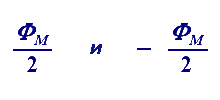
Each of these stream components rotates (moves) in the opposite direction, that is, if F m / 2 rotates in the direction clockwise, then another flow F m / 2 rotates in the direction counterclock-wise.
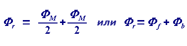
When an AC source supplies current to the stator windings of a single-phase asynchronous motor, it produces a current F m. In accordance with the theory of a double rotation field ( double field revolving theory), this flow can be decomposed into two flows of oppositely directed quantities F m / 2 and moving synchronously with velocity N. We call these two components Φ f (front) and F b (back). The resulting flux from these two streams at any time gives the value of the stator magnetic flux.
At the time of starting the engine, the two components of the flow are directed exactly against each other. They are equal in size and counterbalance each other and, therefore, the efficiency of the torque that the rotor experiences is zero. That is why there is no self-starting single-phase asynchronous motor.
Methods for creating self-starting single-phase asynchronous motors
From the above, one can easily conclude that single-phase asynchronous motors do not self-start because the variable flow produced by the stator consists of two components that compensate each other and, therefore, there is no effective torque.
The solution to this problem is to create a rotating magnetic flux, rather than a pulsating magnetic flux. Then the engine will become self-starting. To do this, one of the components has to have a preponderance relative to the other component of the flow in one direction or the other. Initially, the two components of the flow are in antiphase relative to each other, that is, shifted by 180 degrees. This can be done by adding an additional component of the flow, which after the start can be removed and the engine will continue to work independently.
Depending on how the self-starting single-phase induction motor is self-starting, there are four types of motor:
- With separate windings (Split phase induction motor).
- With a start capacitor (Capacitor start inductor motor).
- With starting capacitor and working winding (Capacitor start capacitor run induction motor).
- With a shifted pole (Shaded pole induction motor).
Comparison of single-phase and three-phase electric motors
- Single-phase asynchronous electric motors are simple in design, reliable and economical in operation, maintenance and operation in comparison with three-phase asynchronous motors.
- The power factor of single-phase asynchronous motors is lower in comparison with three-phase asynchronous motors of the same power.
- Single-phase asynchronous motors of the same dimensions as three-phase asynchronous motors produce about 50% of the capacity.
- Low starting torque for single-phase asynchronous motors.
- The efficiency (efficiency) of single-phase asynchronous motors is lower in comparison with the efficiency of three-phase asynchronous motors.
All section tags Electrical Engineering.