Antipyretics for children are prescribed by a pediatrician. But there are situations of emergency care for fever, when the child needs to give the medicine immediately. Then the parents take responsibility and apply antipyretic drugs. What is allowed to give to infants? How can you bring down the temperature in older children? Which medications are the safest?
Instructions
Regardless of how, the asynchronous electric motor connected to the network, turn off the power of the device in which it is installed. In the presence of high-voltage capacitors discharge them before touching any part of the device.
Be sure to make sure that changing the direction of rotation does not result in failure or accelerated wear of the device, which includes an electric motor.
If three-phase motor feeds from a single-phase network through capacitor , first make sure that the load on its shaft is small, and that if the direction of rotation is changed, it will not increase. Remember that increasing the load with this type of power supply can cause the engine to stop and then ignite it. Then the output of the capacitor, which is not connected to engine , and with one of the supply wires, disconnect from it and switch to another supply wire. If there is a second, starting capacitor, do the same with it (keeping the start button connected in series).
In the event that the motor is powered via a three-phase inverter, do not perform any switching operations. Learn from the instructions to the device how to reverse (by changing the jumper, pressing the button, changing the settings through the menu or by a special combination of keys, etc.), then perform the actions described there.
Nowadays, asynchronous aggregates are used mainly in the engine mode. Devices having a power of more than 0.5 kW are usually made of three-phase, lower power - single-phase. For its long existence, asynchronous motors have found wide application in various branches of industry and agriculture. They are used in the electric drive of hoisting-and-transport machines, metal-cutting machine tools, conveyors, fans and pumps. Less powerful engines are used in automation devices.
You will need
- - ohmmeter
Instructions
Take the three-phase asynchronous engine . Remove the terminal box. To do this, unscrew the two screws that secure it to the case with a screwdriver. The ends of the motor windings are usually output to the 3 or 6 terminal block. In the first case this means that the phase stator windings are connected by a "triangle" or "star". In the second - not connected to each other. In this case, their correct connection comes to the fore. The inclusion of a "star" involves combining the same winding leads (end or start) to the zero point. When connecting the "triangle", connect the end of the first winding with the beginning of the second, then the end of the second - with the beginning of the third, and then the end of the third - with the beginning of the first.
Take the ohmmeter. Use it when the winding leads asynchronous electric motor not marked. Determine the device three windings, designate them conditionally I, II and III. Connect two of any of them in series to find the beginning and end of each of the windings. Apply an alternating voltage of 6 - 36 V to them. To the two ends of the third winding, connect a voltmeter alternating current. The occurrence of an alternating voltage indicates that the windings I and II were connected according to, if it does not, then counter-current. In this case, swap out the terminals of one of the windings. Then note the start and end of the I and II windings. To determine the beginning and end of the third winding, swap the ends of the windings, for example, II and III, and repeat the measurements as described above.
Connect to a three-phase asynchronous motor, which is connected to a single-phase network, a phase-shifting capacitor. Determine its required capacitance (in μF) by the formula C = k * Iph / U, where U is the single-phase voltage, B, k is the coefficient that depends on the winding connection, Iφ is the rated phase current of the motor, A. Note that When the windings of the asynchronous motor are connected by a "triangle", then k = 4800, the "star" is k = 2800. Use paper capacitors IBGCH, K42-19, which must be designed for voltage not less than the supply network voltage. Remember that even with correctly calculated capacitor capacitance, asynchronous electric engine will develop power not more than 50-60% of the nominal value.
Sources:
- Connection of three-phase asynchronous motor to a single-phase network
The asynchronous machine is a device operating on electricity with alternating current, the speed of the machine being not equal to the speed of rotation magnetic field, which is created as a result of the current of the stator winding. So what are the types of such devices and by what principle do they work?
![]()
Instructions
In some countries, similar devices are also referred to as collector machines and are called asynchronous as well as induction, which is explained by the process in which the current in the rotor winding is induced by the stator field. The modern world has found application asynchronous machines as electric motors, which convert electricity energy into mechanical force.
The high demand for such devices is explained by their two advantages: easy and simple manufacture and absence of contact of electricity in the rotor with a fixed part of the machine. But asynchronous machines have their drawbacks - this is a relatively small starting torque and a considerable starting current.
The history of creating devices of the asynchronous type goes even from the Englishman Galileo Ferraris and Nikola Tesla. The first in 1888 published his own studies, in which the theoretical foundations of such an engine were laid out. But Ferrars was wrong, believing that asynchronous machine has a small efficiency. In the same year, the article by Galileo Ferraris was read by a Russian Mikhail Osipovich Dolivo-Dobrovolsky, who in 1889 received a patent for a three-phase asynchronous motor, arranged as a squirrel-cage rotor "squirrel wheel". It is this trio that is the pioneer of the era of mass use of machines for electricity in industry, and now asynchronous devices are the most common engines.
Operating principle asynchronous devices consists in applying an alternating voltage across the windings with current and with the further creation of a rotating magnetic field. The latter, in turn, affects the winding of the rotor, in accordance with the law of electromechanical induction, and interacts with the field of the stator, which rotates. The result of these actions is the impact on each tooth magnetic circuit
The field will be throbbing. Since the order of commutation of inverter leads can be changed by software, it is easy to change the alternation of voltages on the windings, therefore, change the direction of rotation of the motor rotor. Similarly, we find the beginning and end of the second winding and denote them C2 and C5, and the beginning and end of the third - C3 and C6. On average, for each percent of voltage increase, the reactive power consumed increases by 3% or more (mainly due to an increase in the no-load current of the motor), which in turn leads to an increase in the active power losses in the elements electrical network. With this connection, the line voltage is greater than the voltage in phase 1.73 times.
This method is the most "ancient", it is due to the absence until recently of the widespread sale of frequency regulators and their relatively high price. Voltage 380V is applied between the ends of the windings AB, ВС, СА.
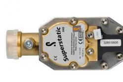
The rotary controller of the asynchronous electric motor 220V serves as a device that changes the pump's impeller speed and outlet pressure (regulates almost the entire possible power range - NOT FREQUENCY!).
For some engines, the ends of the winding phases are output to the terminal board. How to connect the windings in a particular configuration is shown in the figures below.
To change the direction of rotation three-phase electric motor It is necessary to interchange any two phases of the three in the place where the power is connected to the motor.
Engines having a power of more than 1.5 kW require a connection and a starting capacitor. However, these compression rings are lost. First, the wires are assigned to the individual phases of the stator winding.
The diagram of the start device is shown in the figure below.
Often there is a need for a subsidiary farm to connect a three-phase electric motor, and there is only single-phase network (220 V).
Asynchronous motors are of two basic types: with a phase rotor and with squirrel cage rotor, the difference of which consists in different versions of the rotor winding. This is because we attach a 3-way engine to a single vase network. The primary winding contains 120 turns of wire with a diameter of 0.7 mm, with a tap from the middle, secondary - two separate windings of 60 turns with the same wire. The voltage value depends, ultimately, on the characteristics of the machine and the capacitance of the capacitors. It is known that the resistance of the cold filament of an incandescent lamp is 10 times less than the resistance of a hot filament.
If you turn on the AD in 1F network, the torque will be generated only by one winding.
In this case, the motor windings are connected in series. Lighting a light bulb means that the 2 leads belong to the same phase. The tags K1 and H3 (or H2) are put on pins that are in common knots (tied in the first part of the work) with H1 and K3, respectively. In order to create it, it is necessary to shift the phases on the windings using a special circuit.
The capacitors were of the KBG-MN type or others with an operating voltage of at least 400 V. When the generator was switched off on the capacitors, electric charge, so they were safely enclosed to avoid electric shock.
To connect the motor on a rather rare star scheme at startup, with the subsequent transfer to work in the operating mode in the triangle diagram. The engine starts to emit a characteristic sound (buzz). Switching the motor from one voltage to another is done by connecting the windings. Do not overload the engine and work "day and night".
If the engine still buzzes, then this phase should also be put as before, and turn the next phase - II.
Disadvantages are: a reduced and pulsating moment single-phase motor; increased its heating; Not all standard converters are ready for this kind of work, because some manufacturers expressly prohibit the use of their products in this mode.
If you use a dimmer in accordance with its purpose and comply with all conditions of use, you can achieve good results in managing light sources indoors and outdoors.
Quite often, the operation mode of auxiliary mechanized equipment requires lowering the nominal rotation frequencies. To achieve this effect allows you to adjust the speed of the induction motor with your own hands. How to do it in practice (calculation and assembly), using standard control schemes or self-made devices, let's try to understand further.
- Engines with phase rotor
What is an asynchronous motor?
Electric motors of alternating current have found wide enough application in various spheres of our vital activity, in lifting transport, processing, measuring equipment. They are used to transform electric power, which comes from the network, into the mechanical energy of the rotating shaft. The most commonly used are asynchronous AC-DC converters. In them, the rotor and stator rotational frequency are different. A constructive air gap is provided between these active elements.
Both the stator and the rotor have a rigid core made of electrical steel (set type, made of plates), acting as a magnetic core, as well as a winding that fits into the structural grooves of the core. It is the way of organizing or laying the winding of the rotor is the key criterion for classifying these machines.
Motors with squirrel-cage rotor (ADC)
It uses a winding in the form of aluminum, copper or brass rods, which are inserted into the grooves of the core and on both sides are closed by disks (rings). The type of connection of these elements depends on the engine power: for small values the method of joint casting of disks and rods is used, and for large ones - separate manufacture with subsequent welding among themselves. A typical design of such engines can be seen in the illustration below. The stator winding is connected using "triangle" or "star" circuits.
Engines with phase rotor
Connects to the network three-phase winding rotor, by means of contact rings on the main shaft and brushes. The basis is the "star" scheme. The figure below shows a typical design of this engine.

Principle of operation and number of revolutions of induction motors
We will consider this issue on the example of ADR, as the most common type of electric motors for lifting-transport and processing equipment. Voltage from the mains is applied to the stator winding, each of three phases of which is biased geometrically by 120 °. After the voltage is applied, a magnetic field arises that creates by induction the EMF and current in the rotor windings. The latter causes electromagnetic forces that cause the rotor to rotate. Another reason why all this occurs, namely, the EMF occurs, is the difference in speed between the stator and the rotor.
One of the key characteristics of any ADC is the rotational speed, which can be calculated according to the following relationship:
n = 60f / p, rpm
where f - frequency of mains voltage, Hz; p is the number of pole pairs of the stator.
All specifications are indicated on the metal plate fixed on the body. But if it is absent for some reason, it is possible and necessary to determine the speed of rotation by indirect indicators. As a rule, three main methods are used:
- Calculation of the number of coils. The obtained value is compared with the current norms for voltage 220 and 380V (see the table below);

- Calculation of revolutions taking into account the diametrical pitch of the winding. To determine a formula of the form:
where 2p is the number of poles; Z 1 - number of grooves in the stator core; y - actually, the winding step.
The standard values of the revolutions, thus can be represented in the table:

- Calculation of the number of poles along the stator core. Mathematical formulas are used, which take into account the geometric parameters of the product:
2p = 0.35Z 1 b / h or 2p = 0.5D i / h,
where 2p is the number of poles; Z 1 - number of grooves in the stator; b - width of the tooth, cm; h - height of the backrest, cm; D i is the internal diameter formed by the teeth of the core,
After this, according to the received data and the magnetic induction, it is necessary to determine the number of turns, which is checked against the engine's passport data.
Methods for changing engine speed
Adjusting the speed of any three-phase electric motor used in lifting and transporting equipment and equipment allows to achieve the required modes of operation accurately and smoothly, which is far from always possible, for example, due to mechanical reducers. In practice, there are seven basic methods of correcting rotation speed, which fall into two key directions:
- Change in the speed of the magnetic field in the stator. Achieved by frequency control, switching the number of pole pairs or voltage correction. It should be added that these methods are applicable to squirrel-cage motors;
- Change in slip. This parameter can be corrected due to the supply voltage, the connection of additional resistance in electrical circuit rotor, the use of a valve stage or dual power supply. Used for models with a phase rotor.
The most popular methods are the regulation of voltage and frequency (due to the use of converters), as well as the change in the number of pole pairs (realized by organizing an additional winding with the possibility of switching).
Typical regulators of speed regulators
On the market today, you can see quite a wide selection of regulators and frequency converters for asynchronous motors. Nevertheless, for domestic needs of lifting or processing equipment it is quite possible to calculate and assemble on a chip a homemade device based on thyristors or powerful transistors.
An example of a sufficiently powerful regulator circuit for an asynchronous motor can be seen in the illustration below. Due to what you can achieve a smooth control of its operation parameters, reduce energy consumption to 50%, maintenance costs.

This scheme is complicated. For domestic needs, it can be greatly simplified, using as a working element a triac, for example, VT138-600. In this case, the scheme will look like this:

The motor speed will be adjusted by means of a potentiometer, which determines the phase of the input pulse that opens the triac.
As can be judged from the information presented above, the speed of the asynchronous motor depends not only on the parameters of its operation, but also on the efficiency of the functioning of the powered lifting or processing equipment. In today's trading network, you can buy a wide variety of controls, but you can also make a calculation and collect an effective device yourself.
Of the many types of AC motors used in modern electrical engineering, the most widespread, convenient and economical is a motor with a rotating magnetic field, based on the application three-phase current.
To understand the basic idea underlying the design of these engines, let us return again to the experiment depicted in Fig. 264. We saw there that a metal ring placed in a rotating magnetic field comes into rotation in the same direction as the field rotates. The reason for this rotation is the fact that when the field is rotated, the magnetic flux through the ring changes and at the same time currents are induced in the ring, to which the field acts with forces already known to us that create a torque.
In the presence of a three-phase current, i.e., a system of three currents shifted in phase relative to each other by (a third of the period), it is very easy to obtain a rotating magnetic field without mechanical rotation of the magnet and without any additional devices. Fig. 351, but shows how this is done. We have here three coils placed on iron cores, located relative to each other at an angle of 120 °. Through each of these coils passes one of the currents of the system constituting a three-phase current. In the coils, magnetic fields are created, the directions of which are marked by arrows. The magnetic induction of each of these fields varies over time with the same sinusoidal law as the corresponding current (Fig. 351, b). Thus, the magnetic field in the space between the coils is the result of superposition of three variable magnetic fields, which, on the one hand, are directed at an angle of 120 ° with respect to each other, and on the other hand are phase shifted by. The instantaneous value of the resultant magnetic induction is the vector sum of the three constituent fields at a given time:
![]() .
.
If we now look for how the resulting magnetic induction changes with time, the calculation shows that the magnetic induction of the resultant field does not change modulo (retains a constant value), but the direction of the vector turns uniformly, describing the total revolution during one current period.

Fig. 351. Production of a rotating magnetic field with the addition of three sinusoidal fields directed at an angle of 120 ° with respect to each other and displaced in phase by: a) the arrangement of the coils creating a rotating field; b) a graph of the change in field induction with time; c) the resultant induction is constant in modulus and over a period rotates on the circle
Without going into the details of the calculation, let us explain how the addition of three fields gives a constant rotating field. In Fig. 351, b arrows indicate the values of the magnetic induction of three fields at the time when, at the time when, and at the time when, and in Fig. 351, in addition, according to the rule of the parallelogram of magnetic inductions and in these three moments, the directions of the arrows u, u, u correspond to Fig. 351, a. We see that the resulting magnetic induction has the same modulus at all three specified moments, but its direction turns for every third of the period by one third of the circumference.
If a metal ring (or, better yet, a coil) is placed in such a rotating field, currents will be induced in it just as if the ring (coil) were rotating in a stationary field. The interaction of the magnetic field with these currents creates forces that drive the ring (coil) into rotation. This is the basic idea of a three-phase motor with a rotating field, first implemented by MO Dolivo-Dobrovolsky.
The construction of such an engine is clear from Fig. 352. Its fixed part - the stator - is a cylinder assembled from sheet steel, on the inner surface of which there are grooves parallel to the axis of the cylinder. In these grooves are laid the wires that are connected to each other along the end faces of the stator so that they form three coils rotated relative to each other by 120 °, which were discussed in the previous paragraph. The beginning of these coils 1, 2, 3 and the ends of their 1 ", 2", 3 "are connected to six clamps located on the shield, mounted on the machine frame. The location of the clamps is shown in Figure 353.

Fig. 352. Three-phase AC motor in disassembled form: 1 - stator, 2 - rotor, 3 - bearing shields, 4 - fans, 5 - ventilation holes

Fig. 353. Arrangement of clamps on the engine shield
Inside the stator is placed the rotating part of the engine - its rotor. It is also a cylinder, recruited from separate sheets, reinforced on the shaft, along with which it can rotate in bearings located in the side shields (covers) of the engine. At the edges of this cylinder there are ventilation blades which, when the rotor rotates, create a strong jet of air in the engine, which cools it. On the cylindrical surface of the rotor, in the grooves parallel to its axis, there is a series of wires connected by rings at the ends of the cylinder. Such a rotor, shown separately in Fig. 354, is called "short-circuited" (sometimes called a "squirrel wheel"). It comes into rotation when a rotating magnetic field appears inside the stator.
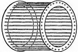
Fig. 354. Short-circuit rotor of three-phase motor
The rotating field is created by a three-phase system of currents supplied to the stator windings, which can be connected to each other either by a star (Figure 355) or by a triangle (Figure 356). In the first case (§ 170), the voltage on each winding is times less than the line voltage of the network, and in the second case it is equal to it. If, for example, the voltage between each pair of wires three-phase network (line voltage) is 220 V, then when the windings are connected by a triangle, each of them is under voltage of 220 V, and if they are connected by a star, each winding is under voltage of 127 V.

Fig. 355. Switching on of the stator windings by a star: a) the circuit for switching on the engine; b) connection of clamps on the shield. Clamps 1 ", 2", 3 "are connected" short "by metal buses, to the terminals 1, 2, 3 are connected the wires of a three-phase network

Fig. 356. Incorporation of stator windings with a triangle: a) the engine switching circuit; b) connection of clamps on the shield. Metal clamps are connected to clamps 1 and 3 ", 2 and 1", 3 and 2 ", to the terminals 1, 2, 3 are connected the wires of a three-phase network
Thus, if the motor windings are rated at 127 V, the motor can operate at normal power both from the 220 V network when connecting its windings with a star, and from the 127 V network when connecting its windings with a triangle. On the plate attached to the frame of each engine, therefore, two network voltages are indicated, under which this engine can work, for example, 127/220 V or 220/380 V. When connected to a network with a lower line voltage, the motor windings are connected by a triangle, and when powered from a network with a higher voltage, they are connected by a star.
The rotating torque of the motor is created by the forces of interaction of the magnetic field and the currents induced by it in the rotor, and the force of these currents (or the corresponding emf) is determined by the relative frequency of rotation of the field relative to the rotor, which itself rotates in the same direction as field. Therefore, if the rotor rotated with the same frequency as the field, then there would be no relative motion of them. Then the rotor would be at rest in relation to the field and no induced e would arise in it. etc., ie, there would be no current in the rotor and could not arise, the forces that drive it into rotation. Hence it is clear that the engine of the described type can only work at a rotor speed that is slightly different from the field rotation frequency, i.e., on the frequency of the current. Therefore, such engines in technology are usually called "asynchronous" (from the Greek word "synchronous" - coinciding or matched in time, the particle "a" denies).
Thus, if the field rotates with a frequency, and the rotor - with a frequency, then the rotation of the field relative to the rotor occurs at a frequency, and it is this frequency that determines the emitted in the rotor. etc. with. and current.
Value ![]() called in the technique of "slipping". It plays a very important role in all calculations. Usually the slip is expressed as a percentage.
called in the technique of "slipping". It plays a very important role in all calculations. Usually the slip is expressed as a percentage.
When we include an unloaded motor into the network, then in the first moments it is equal to or close to zero, the rotation frequency of the field relative to the rotor is large and the rotational frequency of the rotor is e. etc. with. accordingly, it is also great - it is 20 times greater than that of the e. etc., which occurs in the rotor when the engine is running at normal power. The current in the rotor is also much higher than normal. The engine develops quite a considerable torque at the moment of starting, and since its inertia is relatively small, the rotor speed rapidly increases and is almost compared with the field rotation frequency, so that their relative frequency becomes almost zero and the current in the rotor decays rapidly. For small and medium-sized engines, a short-time overload at launching is not a danger, when very powerful engines are started (tens and hundreds of kilowatts), special starting rheostats are used, which weaken the current in the winding; As the normal rotation speed of the rotor is reached, these rheostats are gradually turned off.
As the load of the engine increases, the rotor speed decreases somewhat, the rotation speed of the field relative to the rotor increases, and at the same time the current in the rotor and the torque developed by the motor increase. However, to change the engine power from zero to the normal value, a very small change in the rotor speed is required, up to about 6% of the maximum value. Thus, the asynchronous three-phase motor maintains an almost constant rotational speed of the rotor for very wide load fluctuations. Regulating this frequency is possible in principle, but the corresponding devices are complex and uneconomic, and therefore in practice are used very rarely. If the machines driven by the engine require a different rotational speed than this engine gives, then they prefer to use gear or belt drives with different gear ratios.
It goes without saying that as the motor load increases, that is, the mechanical power it gives, not only the current in the rotor, but also the current in the stator, must increase so that the motor can absorb the appropriate electrical power from the network. This is done automatically due to the fact that the current in the rotor also creates in the surrounding space its magnetic field, which acts on the stator windings and induces some e. etc. with. The connection between the magnetic flux of the rotor and the stator, or, as they say, the "armature reaction", causes the current in the stator to change and ensures the matching of the electrical power drawn from the network to the mechanical power given out by the motor. The details of this process are rather complicated, and we will not enter them.
It is very important, however, to remember that although an underloaded engine takes out the amount of energy that corresponds to the work done by it, but when it is not loaded, when the current in the stator falls, this is due to an increase in the inductive resistance of the stator, i.e., (§ 163), which spoils the operating conditions of the network as a whole. If, for example, 3 kW is sufficient to operate the machine, and we install a 10 kW motor on it, then this enterprise will not suffer much damage - the motor will still take only the power required for its operation, plus losses in the engine itself. But such an underloaded motor has a large inductive resistance and reduces the power factor of the network. It is unprofitable from the point of view of the national economy as a whole. To stimulate the struggle for increasing the power factor, organizations that release electricity to consumers use a system of penalties for the power factor and incentives for raising it too low in comparison with the established norm.
Therefore, when working with engines, the following rules must be adhered to:
1. It is necessary to always choose the engine of the same power as the machine actually actuated by it actually requires.
2. If the engine load does not reach 40% of normal, and the stator windings are included in a triangle, then it is advisable to switch them to a star. In this case, the voltage on the windings decreases by a factor of one, and the magnetizing current is almost three times. In cases where such switching is necessary to produce frequently, the motor is connected to the network by means of a changeover switch according to the scheme shown in Fig. 357. In one position of the switch, the windings are included with a triangle, in the other with a star.

Fig. 357. The scheme of switching the windings of the motor from the triangle (position of the switch I, I, I) to the star (position of the switch II, II, II)
In order to change the direction of rotation of the motor shaft to the opposite, it is necessary to swap the two linear wires connected to the motor. This is easily done with a two-pole switch, as shown in Fig. 358. By switching the switch from position I-I to position II-II, we change the direction of rotation of the magnetic field and at the same time the direction of rotation of the motor shaft.

Fig. 358. Switching circuit for reversing the direction of rotation of a three-phase motor
We have seen that if there are three coils displaced relative to each other by 120 ° in the stator of the motor, the magnetic field rotates at a current frequency, i.e., makes one revolution per second, or 3000 revolutions per minute. Almost at the same frequency, the motor shaft will rotate. In many cases, this speed is too large. To reduce it, in the stator of the engine place not three coils, but six or twelve and connect them so that the north and south poles around the stator circle alternate. In this case, the field is rotated for each current period by only half or a quarter of a revolution, i.e., the shaft of the machine rotates at a frequency of about 1500 or 750 revolutions per minute.
Finally, another practically important remark. In case of damage (breakdown) of the insulation of the frame and casing electric machines and transformers are under tension with respect to the Earth. Touching these parts of machines can be dangerous for people under such conditions. To prevent this hazard, it is necessary to ground the frames and covers of electrical machines and transformers at voltages above 150 V relative to the Earth, i.e., securely connect them with metal wires or rods to the Earth. This is done according to special rules, which must be strictly observed in order to avoid accidents.