Antipyretics for children are prescribed by a pediatrician. But there are situations of emergency care for fever, when the child needs to give the medicine immediately. Then the parents take responsibility and apply antipyretic drugs. What is allowed to give to infants? How can you bring down the temperature in older children? Which medications are the safest?
Federal Agency for Education of the Russian Federation
Kurchatov branch
Kursk State Polytechnic College
on discipline: "Electrical engineering"
on the topic: "AC electric circuits"
I've done the work:
Aseev Eugene Sergeevich
2nd year student of specialty
"Nuclear power plants and installations"
Checked: Gorlov AN
Kurchatov
Introduction
The principle of obtaining a variable emf. The effective value of current and voltage
Vector diagram method
AC circuit with active resistance and inductance
AC circuit with different loads
Sequential circuit containing active resistance, inductance and capacitance
Resonance of voltages and currents
Conductivity and calculation of electrical circuits
Introduction
Until the end of the 19th century, only direct current sources were used - chemical elements and generators. This limited the possibility of transmitting electrical energy over long distances. As you know, to reduce losses in power lines, you must use a very high voltage. However, it is practically impossible to obtain a sufficiently high voltage from a constant-current generator. The problem of the transmission of electrical energy over long distances was solved only with the use of alternating current and transformers.
1. Principle of obtaining the variable emf
Alternating current has several advantages over constant: the alternator is much simpler and cheaper than a constant current generator; alternating current can be transformed; alternating current is easily converted into a constant one; AC motors are much simpler and cheaper than DC motors.
In principle, alternating current can be called any current that changes over time, but in technology this current is called alternating current, it periodically changes both quantities and direction. Moreover, the average value of the force of such a current during the period T is zero. Periodic alternating current is called because at intervals of time T, characterizing its physical quantities take the same values.
In electrical engineering, the most widespread is a sinusoidal alternating current, i.e. a current whose magnitude varies according to the law of the sine (or cosine), which has a number of advantages in comparison with other periodic currents.
Alternating current of industrial frequency is received at power stations by means of generators of an alternating current (three-phase synchronous generators). These are rather complicated electric machines, we will consider only the physical bases of their action, i.e. idea of obtaining alternating current.
Suppose that in a uniform magnetic field of a constant magnet the frame with area S rotates uniformly with angular velocity ω (Fig. 1).
The magnetic flux through the frame will be:
Φ = BS cosα (1.1)
where α is the angle between the normal to the frame n and the magnetic induction vector B. Since the frame ω = α / t is uniformly rotated, the angle α will vary according to the law α = ω t and the formula (1.1) takes the form:
Φ = BScosωt (1.2)
Since the magnetic flux that crosses it changes all the time, the electromagnetic induction law will induce an EMF of induction E:
E = -dF / dt = BSωsinωt = E0sinωt (1.3)
where E0 = BSω is the amplitude of the sinusoidal emf. Thus, a sinusoidal EMF arises in the frame, and if the frame is closed on the load, a sinusoidal current will flow in the circuit.
The quantity ωt = 2πt / T = 2πft, under the sign of the sine or cosine, is called the phase of the oscillations described by these functions. The phase determines the emf value at any time t. The phase is measured in degrees or radians.
The time T of one complete change in the EMF (this time of one frame revolution) is called the EMF period. The change in EMF with time can be depicted in the time diagram (Fig. 2).
The inverse of the period is called the frequency f = 1 / T. If the period is measured in seconds, then the AC frequency is measured in Hertz. In most countries, including Russia, the industrial AC frequency is 50Hz (in the USA and Japan - 60Hz).
The value of the industrial frequency of an alternating current is due to technical and economic considerations. If it is too low, then the dimensions of electric machines increase and, consequently, the consumption of materials for their manufacture; noticeable is the flashing of light in electric bulbs. At too high frequencies, energy losses in the cores of electrical machines and transformers increase. Therefore, the most optimal frequencies turned out to be 50-60 Hz. However, in some cases, alternating currents are used with both a higher and lower frequency. For example, the aircraft uses a frequency of 400 Hz. At this frequency, it is possible to significantly reduce the dimensions and weight of transformers and electric motors, which is more important for aviation than increasing the losses in the cores. The railways use alternating current with a frequency of 25 Hz and even 16.66 Hz.
Current values of current and voltage
To describe the characteristics of an alternating current, it is necessary to select certain physical quantities. The instantaneous and amplitude values for these purposes are inconvenient, and the average values over the period are zero. Therefore, the notion of effective values of current and voltage is introduced. They are based on the thermal action of the current, which does not depend on its direction.
Current values of current and voltage are the corresponding parameters of such a direct current, in which a given amount of heat is emitted in a given conductor over a given period of time as for an alternating current. Let us find the relationship between the effective and amplitude values.
In the active resistance R at constant current I for the period of direct current T, according to the Joule-Lenz law, the following amount of heat will be released:
For an alternating current i in the same resistance R, the following amount of heat will be released in an infinitesimal time interval dt:
dQ = i Rdt (1.5)
where the instantaneous value of the current i is determined by the formula:
i = I0sinωt (1.6)
Then the heat emitted by the alternating current during the period T is equal to:
The integral (1.7) is calculated as follows:

The second integral is zero, since this is an integral of a periodic function in one period. Equating, according to the definition (1.4) and (1.8), we obtain:

Thus, the effective value of the alternating current is √2 times smaller than its amplitude value. Similarly, the effective voltage and EMF values are calculated:
U = U0 / √2; E = E0 / √2 (1.10)
Valid values are indicated in uppercase Latin letters without indices.
2. The method of vector diagrams
The method of vector diagrams-that is, the image of the quantities characterizing the alternating current by vectors, rather than by trigonometric functions, is extremely convenient.
An alternating current, in contrast to a constant one, is characterized by two scalar quantities-the amplitude and phase. Therefore, for mathematical description of alternating current, a mathematical object is required, also characterized by two scalar quantities. There are two such mathematical objects - a vector on the plane and a complex number. In the theory of electrical circuits, both are used to describe alternating currents.
When describing the electric circuit of alternating current with the help of vector diagrams, each vector and voltage are compared with a vector on the plane in polar coordinates, whose length is equal to the amplitude of the current or voltage, and the polar angle is equal to the corresponding phase. Since the AC phase depends on time, it is assumed that all vectors rotate counterclockwise at the frequency of the alternating current. A vector diagram is constructed for a fixed time.
In more detail, the construction and use of vector diagrams will be described below on examples of specific circuits.
3. AC circuit with active resistance and inductance
Consider the circuit (Figure 3), in which a sinusoidal voltage is applied to the active resistor (resistor):
U (t) = U0sin ωt (1.11)
Then, according to Ohm's law, the current in the circuit will be equal to:
I (t) = U (t) / R = U0sin ωt / R = I0 sin ωt (1.12)
We see that the current and voltage coincide in phase. The vector diagram for this chain is shown in Figure 4:
Let us find out how the power in an alternating current circuit with a resistor varies with time. Instantaneous power is equal to the product of the instantaneous values of current and voltage:
p (t) = i (t) u (t) = I0 U0 sin ωt = I0 U0 (1- cos2 ωt) / 2 (1.13)
From this formula we see that the instantaneous power is always positive and pulsates with a doubled frequency (Figure 5):
This means that the electrical energy is irreversibly converted into heat, regardless of the direction of the current in the circuit.
Calculate the average power for the period:
Pcr = 1 / T ∫ p (t) dt = I0U0 / 2T ∫ dt - I0U0 / 2T ∫ cos2ωt dt = (I0U0 / 2T) ∙ T = IU = I R
since the second integral is zero as the integral of the periodic function over the period.
We see that in a circuit with a resistor all the electrical energy irreversibly turns into thermal energy. Those elements of the chain on which the irreversible transformation of electrical energy into other forms of energy (not only into thermal energy) occurs are called active resistances. Therefore, the resistor is the active resistance.
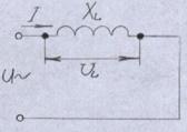
Consider a circuit (Figure 6), in which a sinusoidal voltage (1.11) is applied to the inductor L, which does not have an active resistance (R = 0):
The alternating current flowing through the coil creates in it an EMF of self-induction eL. Then, in accordance with the second rule of Kirchhoff, we can write:
U + eL = 0 (1.15)
According to Faraday's law, the EMF of self-induction is equal to:
eL = -LdI / dt (1.16)
Substituting (1.16) into (1.15), we have:
dI / dt = - eL / L = U / L = U0 sin ωt / L (1.17)
Integrating this equation, we obtain:
I = - U0cos ωt / ω L + const = U0sin (ωt - π / 2) / ωL + const (1.18)
where const is the integration constant, which indicates that the circuit can also have a constant current. In the absence of a direct current, it is zero. In the absence of a direct current, it is zero. Finally we have:
I = I0 sin (ωt - π / 2) (1.19)
where I0 = U0 / ωL. By dividing both sides by √2, we get:
I = U / ωL = U / XL (1.20)
The relation (1.20) is Ohm's law for a chain with an ideal inductance, and the quantity XL = ωL is called the inductive resistance.
From formula (1.19) we see that in the considered circuit the current lags in phase from the voltage by π / 2. The vector diagram for this chain is shown in Figure 7.
Calculate the power consumed by a circuit with a purely inductive resistance.
Instantaneous power is:
p (t) = I0 U0 sin ωt (ωt - π / 2) = - I0 U0 sin2 ωt / 2 (1.21)
We see that it changes according to the law of the sine with a doubled frequency (Figure 8).
Positive power values correspond to the energy consumption of the coil, and negative values - return the stored energy back to the source.
The average power per period is:
Pcr = 1 / T ∫ p (t) dt = (-I0 U0 / 2T) ∫ sin2 ωt dt = 0 (1.22)
We see that the circuit with the power inductance does not consume - it is purely reactive load.
5. AC circuit with different loads
AC circuit with active-inductive load
Consider an electric circuit (Figure 9), in which an alternating current flows through the inductor L, which has an active resistance R:
I = I0 sin ωt (1.23)
The voltage applied to the circuit is equal to the vector sum of the voltage drops on the inductor and on the resistor:
U = UL + UR (1.24)
The voltage across the resistor, as shown above, is in phase with the current:
UR = U0R sin ωt (1.25)
and the voltage on the inductance is equal to the EMF of self-induction with the minus sign (according to the second Kirchhoff rule):
UL = L (dI / dt) = I0 ωLcos ωt = U0Lsin (ωt + π / 2) (1.26)
where U0L = I0 ωL (1.27)
The voltage on the inductor outpaces the current by π / 2. Passing to the effective values of the alternating current (I = I0 / √2, U = U0 / √2), we obtain:
I = UL / XL (1.28)
This is Ohm's law for a circuit with an ideal inductance (ie, not having an active resistance), and XL = ωL is called an inductive resistance. Having constructed the vectors I, UR and UL and using formula (1.24), we find the vector U.
U = √ UR + UL = √ I R + I (ωL) = I√ R + (ωL) = IZ (1.29)
where
Z = √ R + (ωL) (1.30)
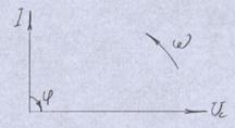
The phase shift φ between current and voltage is also determined from the vector diagram:
tg φ = UL / UR = ωL / R (1.31)
In this circuit, the phase angle between current and voltage depends on the values of R and L and varies from 0 to π / 2.
Now consider how the power in the circuit with active-inductive load varies with time. The instantaneous values of current and voltage can be represented as:
U (t) = U0 sin ωt (1.32)
I (t) = I0 sin (ωt - φ)
(I0 U0 / 2) = (I0 U0 / 2) (1- cos2ωt) cosφ - (I0 U0 / 2) (I0 U0 / 2) 2) sin2ωt sin φ (1.33)
The instantaneous power value has two components: the first term is active, and the second is reactive (inductive). Therefore, the average power per period is not zero:
Pcp = 1 / T ∫ pdt = (I0 U0 / 2T) cosφ ∫dt - (I0 U0 / 2T) cosφ ∫ cos2ωt dt -
- (I0 U0 / 2T) sin φ ∫ sin2ωt dt = (I0 U0 / 2) cosφ (1.34)
AC circuit with capacitance
Consider an electrical circuit in which an alternating voltage (1.11) is applied to capacitance C (Figure 11). The instantaneous value of the current in the circuit with the capacitance is equal to the charge velocity on the plates of the capacitor:
I = dq / dt (1.35)
but, since q = CU, then
I = C (dU / dt) = ωCU0 cos ωt = I0 sin (ωt + π / 2) (1.36)
ωCU0 = I0 (1.37)
In this circuit, the current is ahead of the voltage by π / 2. Passing to the effective values of the alternating current (I = I0 / √2, U = U0 / √2) in formula (1.37), we obtain:
I0 = U / Xc (1.38)
This is Ohm's law for an AC circuit with a capacitance, and the magnitude
Xc = 1 / ωC is called the capacitive resistance. The vector diagram for this chain is shown in Fig. 12.
We find the instantaneous and average power in the circuit containing the capacitance. Instantaneous power is:
p (t) = i (t) u (t) = I0U0 sin (ωt + π / 2) sin ωt = IUsin2 ωt (1.39)
The instantaneous power changes with a doubled frequency (Figure 13). In this case, the positive power values correspond to the capacitor charge, and the negative values correspond to the charge and the return of the stored energy to the source. The average power in the period is zero here
Pcr = 1 / T ∫ p (t) dt = IU / T ∫ sin2 ωt dt = 0 (1.40)
since in the circuit with the capacitor, the active power is not consumed, but the electric energy is exchanged between the capacitor and the source.
AC circuit with active-capacitive load
A real AC circuit with a capacitance always contains an active resistance-the resistance of the wires, the active losses in the capacitor, and so on. Consider a real circuit consisting of a series-connected capacitor C and an active resistance R (Figure 14). In this circuit, the current I = I0 sin ωt flows.
In accordance with the second rule of Kirchhoff, the sum of the voltages on the resistor and on the capacitance is equal to the applied voltage:
U = UR + UC (1.41)
The voltage across the resistor coincides in phase with the current:
UR = U0R sin ωt (1.42)
and the voltage across the capacitor lags the current:
UC = U0C sin (ωt - π / 2) (1.43)
Having constructed the vectors I, UR and UC and using formula (1.41), we find the vector U. The vector diagram for this circuit is shown in Fig. 15.
As can be seen from the vector diagram, the modulus of the vector U is
U = √ UR + UC = √ I R + I (1 / ωC) = I √ R + (1 / ωC) = IZ1 (1.44)
where
Z1 = √ R + (1 / ωC) (1.45)
is called the impedance of the circuit.
The phase shift φ between the current and voltage in a given circuit is also determined from the vector diagram:
tg φ = UC / UR = (1 / ωC) / R (1.46)
In the considered circuit, the angle of phase shift between current and voltage depends on the values of R and C and varies from 0 to π / 2.
Let us now consider how the power in the circuit with active-capacitive load varies with time. The instantaneous values of current and voltage can be represented as:
U (t) = U0 sin ωt
I (t) = I0 sin (ωt + φ) (1.47)
Then the instantaneous power value is:
i (t) = I (t) U (t) = I0 U0 sin ωt sin (ωt + φ) = (I0 U0 / 2) = (I0 U0 / 2) (1- cos2ωt) cosφ + (I0 U0 / 2) sin2ωt sin φ (1.48)
The instantaneous power value has two components: the first term is active, and the second is reactive (capacitive). Therefore, the average power per period is not zero:
Pcr = 1 / T ∫ pdt = I0U0 / 2T cosφ ∫ dt - I0U0 / 2T cosφ ∫ cos2 ωtdt + I0U0 / 2T ∙
sin φ ∫ sin2ωt dt = I0U0 / 2T cosφ (1.49)
and is active power. The electrical energy corresponding to this power is converted into the active resistance R into heat.
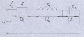
6. Serial circuit, containing active resistance, inductance and capacitance
Now consider the alternating current circuit, which contains inductance, capacitance and resistor, connected in series (Fig. 16).
The voltage applied to the circuit is equal to the vector sum of the voltage drops on the inductor, on the capacitor and on the resistor:
U = UL + UC + UR (1.50)
The voltage across the resistor coincides in phase with the current, the voltage on the coil is ahead of the current in phase by π / 2, and the voltage on the capacitor lags behind the current in phase by π / 2. You can record these voltages as follows:
UR = U0R sin ωt = I0R sin ωt
UL = U0Lsin (ωt + π / 2) = I0 ωL (ωt + π / 2) (1.51)
UC = U0C sin (ωt - π / 2) = (I0 / ωC) sin (ωt - π / 2)
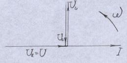
Since we know the amplitudes and phases of these vectors, we can construct a vector diagram and find the vector U (Figure 17)
From the obtained vector diagram we can find the modulus of the vector of the voltage U applied to the circuit and the phase shift φ between the current and voltage:
U = √ UR + (UL - UC) = I √ R + (ωL- 1 / ωC) = IZ (1.52)
Z = √ R + (ωL- 1 / ωC) (1.53)
is called the impedance of the circuit. It can be seen from the diagram that the phase shift between current and voltage is determined by the equation:
tg φ = (UL - UC) / UR = (ωL- 1 / ωC) / R (1.54)
As a result of the construction of the diagram, we obtained a stress triangle whose hypotenuse is equal to the applied voltage U. The phase difference between current and voltage is determined by the ratio of the vectors UL, UC and UR. For UL\u003e UC (Figure 17), the angle φ is positive and the load is inductive. With UL< UC угол φ отрицателен и нагрузка имеет емкостный характер (рис. 18, а). А при
UL = UC angle φ is zero and the load is purely active (Figure 18, b).
Dividing the sides of the stress triangle (Figure 17) by the value of the current in the circuit, we obtain a triangle of resistances (Figure 19, a), in which R is the active resistance, Z is the impedance, and x = xL-xC is the reactance. Besides,
R = Zcosφ; x = Zsinφ (1.55)
Multiplying the sides of the voltage triangle by the value of the current in the circuit, we obtain a triangle of powers (Fig. 19, b). Here S is the total power, Q is the reactive power and P is the active power. From the power triangle follows:
S = IU = √P + Q; Q = Ssin φ; P = S cos φ = IU cos φ (1.56)
Reactive power Q is always associated with the exchange of electrical energy between the source and the consumer. It is measured in volt-ampere reactive (VAR).
The total power S contains both active and reactive components - this is the power that is consumed from the source of electricity. At P = 0, all the total power becomes reactive, and at Q = 0, it is active. Consequently, the components of the total power are determined by the nature of the load. The total power is measured in volts-amperes (VA). This value is indicated on the plates of the AC devices.
The active power P is related to the electrical energy that can be converted into other types of energy - heat, mechanical work, etc. It is measured in Watts (Watts). The active power depends on the current, voltage and cos φ. As the angle φ increases, cos φ and power P decrease, and as the angle φ decreases, the active power P increases. Thus, cos φ shows how much of the total power can theoretically be converted into other types of energy. cos φ is called the power factor.
For more rational use of AC power generated by electric power sources, try to make a load such that cos φ in the circuit is close to unity. In practice, it is rather difficult to achieve this at the scale of the enterprise and cos φ = 0.9 - 0.95 is a good indicator.
At low values of cos φ, additional losses occur on the heating of the conductor.
Suppose that the same active power is transmitted at the same voltage to two equal loads with cos φ0 = 1 and cos φ1<1. Тогда
I0U cos φ0 = I1U cos φ1 (1.57)
I1 = I0 / cos φ1 (1.58)
The power that is expended on heating the wires is
P1 = I1 R = I0 R / cos φ1 (1.59)
that is, the heat loss of the wires is inversely proportional to the square of the power factor. It should be so, because the reactive power creates additional reactive current in the wires, and the losses for heating the wires are proportional to the square of the current. Therefore, an increase in cos φ is of great practical importance.
7. Resonance of voltages and currents
Resonance Resonance
When the inductance and capacitance voltages UL and UC, mutually shifted by 180, are equal in magnitude, they completely compensate each other (Figure 18, b). The voltage applied to the circuit is equal to the voltage at the active resistance, and the current in the circuit coincides in phase with the voltage. This case is called stress resonance.
The condition for the resonance of voltages is the equality of the voltages on the inductance and capacitance or the equality of the inductive and capacitive resistances of the circuit:
xL = xC or ωL = 1 / ωC (1.60)
When the voltage is resonant, the current in the circuit is
I = U / √R + 0 = U / R (1.61)
that is, the circuit in this case has the smallest possible resistance, as if only the active resistance R is turned on. The current in the circuit reaches a maximum value.
At a resonance of a voltage on reactive resistances, xL and xC can significantly exceed the voltage applied to the circuit. If we take the ratio of the applied voltage to the voltage on the inductance (or capacitance), we get
U / UL = IZ / I xL = Z / xL or UL = U xL / R (1.62)
that is, the voltage on the inductor will be greater than the applied voltage in xL / R times. This means that at resonance of voltages on certain sections of the circuit, strains can arise which are dangerous for the insulation of devices included in this circuit. A vector diagram for the case of stress resonance is shown in Fig. 18 b.
If in a series circuit containing an active resistance, inductance and capacitance, the value of one of the elements of the circuit (for example, capacitance) is changed with the applied voltage unchanged, then many quantities characterizing the current in the circuit will change. Curves showing how the current, voltage change, are called resonant. Resonance curves with a change in capacitance are shown in Fig. 20.
Resonance currents
Unlike successive AC circuits, where the current flowing through all the circuit elements is the same, in parallel circuits the voltage applied to the parallel branches of the circuit is the same.
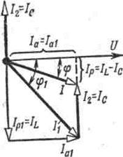
Consider the parallel inclusion of the capacitance and branch, consisting of inductance and active resistance (Figure 21).
Both branches are under the same applied voltage U. We construct a vector diagram for this circuit. As the main vector, we choose the vector of the applied voltage U (Figure 22).
Then we find the length of the vector I1 from the relation
I1 = U / z1 = U / √R1 + xL (1.63)
and postpone this vector with respect to the vector U at an angle φ1, which is determined by the formula
tg φ1 = xL / R1 (1.64)
The current vector I1 thus obtained can be decomposed into two components: the active Ia1 = I1 cos φ1 and the reactive Ip1 = I1 sin φ1 (Figure 22).
The magnitude of the current vector I2 is found from relation
I2 = U / xC = U / (1 / ωC) = ωCU (1.65)
and we plot this vector at an angle of 90 counterclockwise relative to the vector of the applied voltage U.
The total current I is equal to the geometrical sum of the currents I1 and I2 or the geometrical sum of the reactive current Ip1-I2 = IL-IC and the active current Ia1. the length of the vector I is
I = √ (IL-IC) + (Ia1) (1.66)
The phase shift between the common current I and the applied voltage U can be determined from relation
tgφ = (IL-IC) / Ia1 (1.67)
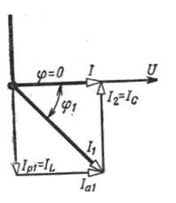
From the vector diagram it can be seen that the length and position of the total current vector depend on the relationship between the reactive currents IL and IC. In particular, with IL\u003e IC, the total current lags in phase from the applied voltage, with IL< IC ─ опережает его, а при IL = IC ─ совпадает с ним по фазе. Последний случай (IL = IC) называется резонансом токов. При резонансе токов общий ток равен активной составляющей тока в цепи, то есть происходящие в цепи процессы таковы, как будто в ней содержится только активное сопротивление (в этом случае φ = 0 и cos φ = 1). При резонансе общий ток в цепи принимает минимальное значение и становится чисто активным, тогда как реактивные токи в ветвях не равны нулю и противоположны по фазе.
If in the parallel circuit shown in Figure 21, to change the capacitance value with the constant applied voltage, then many quantities that characterize the current in the circuit will change. Curves showing how the current changes, the voltages on the sections of the circuit and the phase shift between current and voltage are called resonant.
§4.1. Alternating current, acquisition, parameters.
Variables called a periodic current, the values of which are repeated after certain time intervals, called the period. Period (T, seconds) of one complete oscillation.
Fig.4-1. Model of the alternator.
![]()
Fig.4-2. Sine wave plot.
The source of the magnetic field lines is a permanent magnet NS, between the poles of which is a cylindrical rotor (rotating part). The rotor, in order to reduce losses on eddy currents, is recruited from separate thin sheets of electrical steel, insulated with varnish film from each other. The poles are given such a form that in the air gap between them and the rotor the magnetic induction varies according to the law of the sine
![]() ,
,
where a is the angle between the plane of the coil located on the rotor and the neutral plane OO '. When the rotor rotates with the angular velocity ω, in each active side of the coil turn (number of turns W), according to the phenomenon of electromagnetic induction, EMF is induced. Then, the EMF inducted at the ends of this coil will be equal to
e i - EMF inducted in one active side of the coil winding; 2 - number of active parties in one turn; W is the number of turns; ωt = a. Here .
It follows from expression (1) that when creating such a model of the generator, the EMF arising in the winding fixed on the rotor varies according to the law of the sine. To connect to such a load generator you need:
1. the ends of the winding are connected to the contact rings;
2. Attach the brushes to the contact rings, by means of which we remove the EMF, and connect the load.
AC parameters.
2. Cyclic frequency - the number of total oscillations per second.
The unit of measurement is Hz = 1 / s.
3. Instantaneous value of current i, voltage u, emf e is the value of these values at an arbitrary moment of time, for example, time t, instantaneous value of current i (see graph).
4. The amplitude or maximum value of the current I max, the voltage U max, the emf E max is the largest of the instantaneous.
5. The actual value is the current value, which is determined in AC circuits by means of measuring devices.
Here U, E and I are effective values.
6. Average value of the value for the period. Because, during one half of the period, the current flows in one direction, and during the other half the same amount of electricity flows in the opposite direction, then the average value of the current over the period is 0.
§ 4.2. Phase of alternating current. Phase shift.
Suppose that two identical turns 1 and 2 are fixed at the anchor of the generator, shifted in the gap by an angle φ, as shown in Fig. 4-3. When the armature rotates, an EMF of induction of the same frequency ω and amplitude E max in Fig. 4-4 will be induced in the turns, because the turns rotate with the same angular velocity in the same magnetic field.
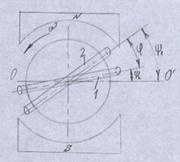
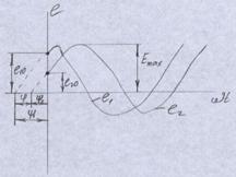
The position of the turns is given by the angles ψ 1 and ψ 2 for an arbitrary moment of time, which can be set to t = 0. The planes of the turns do not coincide with the neutral plane OO '. The instantaneous EMF values as a function of time will be determined by the expressions:
Consequently, at the time t = 0, the emf is nonzero:
![]() ;
; ![]() .
.
Electrically, the angles ψ 1 and ψ 2 determine the emf values at the initial time and are called initial phase angles or initial phases.
The time shift is determined by the difference in the initial phases and is called angle of phase shift or phase shift φ. (Fig. 4-4).
§ 4.3. Vector diagrams.
Adding, subtracting currents, the voltages of two sinusoidal quantities having different initial phases, is a laborious operation. Therefore, it became necessary to replace the sinusoidal quantities with a vector whose length is equal to the effective value of a given quantity, and its position relative to the neutral plane will be determined by the initial angle. Such a replacement is called a vector diagram. The set of several vectors corresponding to the zero moment of time is called vector diagram.
Section 4.4. Features of electrical circuits of alternating current.
When studying electrical circuits, it must be remembered that the electric current is inextricably linked with the magnetic field. Thus, when there is a current in the electrical circuit and in the environment, there are magnetic and electric fields. In addition, the electrical circuit converts electromagnetic energy into thermal energy.
In real circuits, the electric and magnetic fields are distributed along the whole axis. But such a uniform distribution of fields is rare, for example, in energy transmission lines. As a rule, the magnetic and electric fields are distributed unevenly along the chain, and magnetic fields (inductive coils) are sharply expressed in some areas, while on the other - electric (capacitors). There are also sections of circuits where the conversion of electromagnetic energy into thermal energy (resistors) takes place. These chains, called chains with lumped parameters, allow you to study the properties of individual sections, and then consider the operation of the circuit as a whole.
§ 4.5. AC circuit with active resistance.
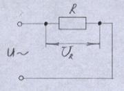
u is the instantaneous voltage.
The current in the chain is determined by Ohm's law:
where U is the current one; R - resistance. An example is an incandescent lamp.
Such a circuit consumes power, called the active
I is the effective value of the current.
Under active power, one can approximately consider the useful power that is involved in the conversion of electrical energy into other types of energy.
Vector diagram.
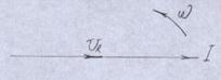
When drawing a diagram, remember that vectors rotate counterclockwise with angular velocity ω or they say with an angular frequency ω equal to
Here, U R is the voltage at the active resistance, equal to
in the active resistance, the current vector and the voltage vector coincide in direction.
4.6. AC circuit with capacitance.
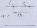
Current in the circuit
where X C is the capacitive resistance of the circuit, equal to
![]() ,
,
here c - capacity in Faradah, and since. this value is very large, and the networks have capacitance values in μF, then they often use formula
![]() ,
,
here s in uF.
In this circuit, regardless of the direction of the current, at the sections 0-1,2-3 (see the graph of alternating current) there is a consumption of electric energy, the capacitor accumulates it on the plates and it is present in this circuit in the form of the energy of the electric field. At these time intervals, the circuit operates as a consumer and the power values are taken with a "+" sign.
When the voltage at the input to the circuit is characterized by the area 1 - 2, 3 - 4, the stored electrical energy in the circuit with the capacitance returns to the network, the circuit behaves like a generator, and the power value is taken with the sign "-". Therefore, the active power consumed by such a circuit is 0. The highest value of the power consumed by the circuit is called reactive power and is determined
[var] - volt ampere reactive.
Vector diagram.
Here U C is the voltage across the capacitive resistance
As can be seen from the vector diagram the vector of the current is ahead of the voltage vector by an angle φ = 90 °. In this case, they say, φ = 90 ° is leading, i.e. the vector of the current is ahead of the voltage vector by an angle of 90 °.
§ 4.7. AC circuit with inductance.
Current in the circuit
where X L is the inductive resistance of the circuit, equal to
![]() ,
,
where L - inductance (Гн) - the parameter characterizing properties of coils of coils of electric devices and machines.
In this circuit, also in accordance with the shape of the voltage applied to the circuit and at different times (sections 0 - 1, 1 - 2), first comes the consumption of electrical energy, which accumulates in the form of the energy of the magnetic field, after which it returns to the network. Therefore, P = 0. In this case, the largest value of power is called reactive power inductance.
Vector diagram.

Here, the voltage on the inductive resistance is
As can be seen from the vector diagram the current vector lags behind the voltage vector by an angle φ = 90 °. Now, under the notation φ = 90 ° - lagging - it is necessary to understand that the current vector lags behind the voltage vector by an angle φ = 90 °.
§ 4.8. Unbranched alternating current circuit with R, X L, X C.
Current in the circuit
where Z is the impedance of the circuit, equal to
![]() .
.
The relationship between these resistances can be graphically depicted as a rectangular resistance triangle.

Vector diagram. The order of construction.
1. Find the voltage on the elements of the circuit
2. Select the current and voltage scale.
When choosing a scale, consider:
§ the length of the current vector should be slightly greater than or equal to the length of the common voltage vector;
§ The voltage scale should be such that the lengths of voltage vectors on the circuit elements are obtained by integers or fractional 5 (with a fraction of 0.5, for example 2.5).
3. We plot the current vector horizontally. The length of the current vector is equal to the numerical value of the current divided by the scale.
4. Taking into account the angles of the phase shift in the active, inductive and capacitive resistances, we plot the stress vectors on the elements of the circuit. To correctly postpone the stress vectors do this:
§ Circumvent the chain clockwise, but it is possible and in another way;
§ to obtain a voltage vector at the terminals of the circuit, it is necessary to add all the vectors in turn to each other, i.e. the beginning of the second must go from the end of the first, and the beginning of the first will coincide with the beginning of the current vector. For our circuit, the voltage vector at the terminals of the circuit is
![]() ;
;
§ do not forget that the vectors rotate counter-clockwise.
![]()
The angle φ is marked by an arrow, the direction of the arrow from the current vector to the voltage vector. The diagram is constructed for the case X L\u003e X C /
For the case X L For the case X L = X C Such a vector diagram shows that a stress resonance occurs in the circuit. at a voltage resonance, such a chain behaves like a chain with a purely active load, i.e. Z = R, cosφ = 1, since φ = 0, then Q = 0, P = S, and the voltage at the terminals of the circuit is equal to the voltage at the active resistance. To achieve a voltage resonance, one can select inductance, capacitance, reactive resistances, or feed such a circuit with a resonant frequency And the other is the reactive component of the total current, equal to the difference between the reactive component of the coil current and the capacitor current Thus, the total current The angle of the total current shift from the voltage is determined through its tangent (Fig. 4-18): Fig.4-18. Vector diagram for a branched chain. Fig.4-19. Vector diagram for resonance currents. The current in the unbranched part of the circuit may lag behind the voltage by an angle φ for I L\u003e I C, or be ahead of it at I L , and power, t. φ = 0, and cosφ = 1. Thus, the total current is equal to the active component of the coil current. In this case, the total current is always less than the current in the coil, because the active component of the coil current is always less than the coil current (I a 1
The ratio of the current in the loop or in the coil (I 1 ≈ I 2) to the total current at resonance (I re) which is the quality factor of the circuit, shows how many times the current in the parallel circuit at resonance is greater than the total current in the supply wires. In this case, the maximum power required to obtain a magnetic field (U / IL) is equal to the maximum power expended for obtaining an electric field (UI C), and hence the maximum values of energy in the magnetic and electric fields of the circuit WL m = WC m As in the oscillatory circuit considered above, in one quarter of a period the energy stored in the electric field is wholly obtained from the magnetic field, and during the second quarter of the period the energy stored in the magnetic field is wholly obtained from the electric field th field. From the generator, only the energy consumed in the active resistance enters the circuit. Because the reactive components of the current cancel each other, then in the generator circuit only the active current passes due to the energy losses in the active resistance. §4.10. Power factor. To fully use the generator, it must operate at a nominal voltage U n with a rated current I n and cosφ = 1. In this case, the generator develops the largest active power equal to its total rated power, A decrease in cosφ causes a proportional decrease in the active power, i.e. incomplete use of the rated power of the generator. At a power receiver operating at a constant rated voltage U n and with a constant active power P, the current varies inversely proportional to cosφ, because Consequently, a decrease in cosφ causes an increase in current and an increase in the power of the losses for heating the wires I 2 r. For these reasons, they tend to increase the cosφ of each unit to a value close to unity. Control questions: 1. What is called an alternating electric current? 2. How can I represent an alternating electric current? 3. Period, frequency, amplitude of alternating current. 4. Instantaneous and effective values of current, voltage and EMF. 5. Phase of alternating current. Phase shift. 6. Vector diagrams of an alternating current circuit. 7. What are the features of AC electric circuits? 11. What is an unbranched AC circuit with active resistance, capacitance and inductance? 12. How to build a vector diagram of an unbranched AC circuit? 13. What is a branched AC circuit? 14. Power factor. Methods for representing sinusoidal currents, voltages, EMFs In modern technology, various currents and voltages are widely used: sinusoidal, rectangular, triangular, etc. The value of current, voltage, EMF at any instant t is called the instantaneous value and is denoted by small lower-case letters, respectively i = i (t); u = u (t); e = e (t). The currents, voltages and EMFs, whose instantaneous values are repeated at regular intervals, are called periodic, and the smallest time interval through which these repetitions occur is called the period T. If the curve of the variation of the periodic current is described by a sinusoid, then the current is called sinusoidal. If the curve is different from the sinusoid, then the current is not sinusoidal. On an industrial scale, electrical energy is produced, transmitted and consumed by consumers in the form of sinusoidal currents, voltages and EMF, When calculating and analyzing electrical circuits, several methods of representing sinusoidal electrical quantities are used. Analytical method i (t) = I m sin (ωt + ψ i), for voltage u (t) = Um sin (ωt + ψ u), e (t) = E m sin (ωt + ψ e), In the equations (2.1 - 2.3) we denote: I m, U m, E m - amplitudes of current, voltage, EMF; The values of i, I m - are measured in amperes, the values of U, U m, e, E m - in volts; the value of T (period) is measured in seconds (s); frequency f - in hertz (Hz), the cyclic frequency ω has the dimension rad / s. The values of the initial phases ψ i, ψ u, ψ e can be measured in radians or degrees. The value of ψ i, ψ u, ψ e depends on the origin of the time t = 0. The positive value is put to the left, the negative value is to the right. Timeline The time diagram represents a graphical representation of a sinusoidal value at a given scale as a function of time (Figure 2.1). i (t) = I m sin (ωt - ψ i). Graphoanalytical method Graphically, sinusoidal magnitudes are represented as a rotating vector (Figure 2.2). Rotation is assumed to be counter-clockwise with a rotation frequency ω. The magnitude of the vector at a given scale represents the amplitude value. The projection on the vertical axis is the instantaneous value of the value. The set of vectors representing sinusoidal quantities (current, voltage, EMF) of the same frequency is called a vector diagram. Vector values are marked with a dot above the corresponding variables. The use of vector diagrams makes it possible to significantly simplify the analysis of AC circuits, making it simple and intuitive. At the heart of the graphoanalytic method of analyzing alternating current circuits is the construction of vector diagrams. An example (Figure 2.3) i 1 (t) = I m1 sin (ωt) The first Kirchhoff law is satisfied for instantaneous currents: i (t) = i 1 (t) + i 2 (t) = I m1 sin (ωt) + I m2 sin (ωt - ψ2) = I m sin (ωt + ψ). Equate the projections on the vertical and horizontal axes (Figure 2.4): I m sin ψ = I m2 sin ψ 2; I m cos ψ = I m2 cos ψ 2 + I m1; From the equalities (2.4 - 2.5) we obtain Inductance A magnetic field is formed around any conductor with current, which is characterized by a vector of magnetic induction B and a magnetic flux Ф: If a field forms several (w) conductors with the same current, then the concept of flux linkage ψ The relation of the current-to-current coupling, which creates it, is called the inductor coil When the flux linkage changes in time, according to the Faraday law, an emf of self-induction e L = -dψ / dt. Taking into account relation (2.8) for eL, we obtain e L = - L · di / dt. This EMF always prevents the change of current (Lenz's law). Therefore, in order to conduct current through the conductors all the time, it is necessary to apply a compensating voltage to the conductors Comparing equations (2.9) and (2.10), we obtain u L = L · di / dt This relation is an analog of Ohm's law for inductance. Structurally, the inductance is made in the form of a coil with a wire. Conventional designation of inductance A coil with a wire in addition to the property of creating a magnetic field has an active resistance R. Conditional designation of real inductance. The unit of inductance measurement is Henry (HH). Fractional units are often used 1 μH = 10 -6 GH; 1 μH = 10 -3 HH. Capacity All conductors with electric charge create an electric field. The characteristic of this field is the potential difference (voltage). The electrical capacitance is determined by the ratio of the conductor charge to the voltage Taking into account relation we obtain the current-voltage relationship formula i = C · du C / dt. For convenience, it is integrated and obtained u C = 1 / C · ∫ i dt. This relation is an analog of Ohm's law for capacity. Structurally, the capacitance is made in the form of two conductors separated by a dielectric layer. The shape of the conductors can be flat, tubular, spherical, etc. The unit of measurement of capacity is Farad: 1Ф = 1Кл / 1В = 1Colon / 1Volt. It turned out that Farad is a large unit, for example, the capacity of the globe is ≈ 0.7 F. Therefore, fractional values are most often used 1 pF = 10 -12 F, (pF is the picofarad); The symbol for capacity is the symbol Element R (resistor) Set the voltage and current in the form of relations u (t) = Um sin (ωt + ψ u), i (t) = I m sin (ωt + ψ i). It is known that for a resistor ψ u = ψ i, then for p we get p (t) = u (t) i (t) = U m I m sin 2 (ωt + ψ i). Equation (2.32) shows that the instantaneous power is always greater than zero and varies with time. In such cases, consider the average power for a period T If we write U m and I m in terms of the effective values of U and I:, then we obtain In form, equation (2.34) coincides with the power at a constant current. The quantity P equal to the product of the effective values of current and voltage is called the active power. The unit of its measurement is Watt (W). Element L (inductance) It is known that in the inductance the phase relationship ψ u = ψ i + 90 °. For instantaneous power has Averaging equation (2.35) in time over the period T, we obtain To quantify the power in the inductance, use the value Q L equal to the maximum value p L Q L = (U m I m) / 2 and call it reactive (inductive) power. The unit of its measurement was chosen to be VAR (reactive volt-ampere). Equation (2.36) can be written in terms of the effective values of U and I, and using the formula U L = I X L, we obtain Element C (capacity) It is known that in the capacitance the phase ratio ψ u = ψ i is 90 °. For instantaneous power, we obtain p C (t) = u (t) I (t) = (U m I m) / 2 · sin (2ωt). The average value for the period here is also zero. By analogy with equation (2.36), we introduce the quantity Q C = I 2 X C, which is called the reactive (capacitive) power. The unit of its measurement is also VAR. If there are elements R, L and C in the circuit, the active and reactive powers are determined by equations where φ is the angle of phase shift. Introduce the notion of the total power of a chain With allowance for equations (2.37) and (2.39), (2.40) can be written in the form The unit of measurement of the total power is VA - volt-ampere. Ohm's law Under Ohm's law, in a complex form, they understand: Í = Ú / Z The complex resistance of the chain segment is a complex number, the real part of which corresponds to the value of the active resistance, and the factor for the imaginary part - to the reactance. By the type of recording of the complex resistance, one can judge the nature of the chain segment: R + j X - active-inductive resistance; Single-phase AC electric circuits Most consumers of electrical energy work on alternating current. Currently, almost all of the electrical energy is generated in the form of AC power. This is explained by the advantage of production and distribution of this energy. Alternating current is received at power stations, converting with the help of generators mechanical energy into electrical energy. The main advantage of an alternating current as compared with a constant one is the possibility to increase or decrease the voltage with the help of transformers, to transmit electric energy over long distances with minimal losses, in three-phase power supplies one can obtain two voltages: linear and phase. In addition, generators and AC motors are simpler in design, more reliable in operation and easier to operate than DC machines. In AC electrical circuits, the most commonly used sinusoidal form, characterized by the fact that all currents and voltages are sinusoidal functions of time. In alternating current generators, an EMF is produced that varies in time according to the law of the sine, and thus provides the most advantageous operational mode of operation of electrical installations. In addition, the sinusoidal form of current and voltage allows accurate calculation of electrical circuits using the method of complex numbers and an approximate calculation based on the vector diagram method. In this case, the Ohm and Kirchhoff laws are used for the calculation, but written in vector or complex form. Single-phase alternating current
Variable electric current in comparison with a constant one has a great advantage in everyday life and in production. The advantage of the alternating current is primarily due to the fact that the voltage and current can be transformed (converted) almost without loss of energy in a very wide range and transmitted over long distances. That is why alternating current and voltage are widely used in industry. In industry (in power plants), alternating current is generated by alternating current generators in which the phenomenon of electromagnetic induction is used. The simplest scheme for obtaining alternating current and voltage is shown in Fig. 7: The wire frame (revolution) rotates in a uniform magnetic flux at a constant speed. Changes in the magnetic flux passing through the surface of the frame will occur continuously, while the flux created by the electromagnet (inductive coil and steel core) will remain unchanged. In the frame there is an EMF induction, which is measured by a voltmeter. For visual persuasion, consider the frame positions at different times in Fig. 8. At the initial moment (Figure 8, a) the plane of the frame is perpendicular to the magnetic lines, respectively, the magnetic flux through the frame is maximal, after a quarter of the period (Figure 8, at) the frame is parallel to the magnetic lines and the magnetic flux is zero: But EMF induction is determined not by the flow itself, but by the rate of its change, in the first position of the frame (Figure 8, a) EMF will be 0, and accordingly in the third position (Figure 8, at) EMF induction will have the maximum value. For other values, the EMF of induction also changes its value and sign, i.e. will be a variable. The current arising in the frame under the action of EMF induction, with time will change like the EMF itself. Such a current is called alternating sinusoidal current. The time interval during which the current makes one complete oscillation (one revolution) is called the period of the alternating current. The period of oscillation is denoted by T, the number of oscillations per second. Call the frequency of the current and denoted by the letter f. The unit of frequency is denoted in Hertz (Hz): f = 1/T or T = 1/f
. It should be noted that in our country and in most other countries in the industry and in everyday life an alternating current with a frequency of 50 Hz is used. For example, if the generator rotates at a speed of 3000 rpm (60 seconds), and has one pole (Figure 7), then: f = 3000/60 = 50 Hz.
Equations and graphs of sinusoidal quantities
Let's consider in more detail the analysis of electric circuits of an alternating current of sinusoidal values with the help of equations and graphs. At any point in the air gap, the position of which is determined by the angle β, read from the neutral plane (neutral) opposite the clockwise direction, the magnetic induction is expressed by the equation: B = Bmsinβ, Where AT
- magnetic induction; Bm
- amplitude (largest value) of magnetic induction; sinβ -angle of magnetic field. The neutral plane is perpendicular to the axis of the poles and divides the magnetic system into symmetrical parts, one of which is conditionally northern and the other is southern. The greatest value (see Figure 9) is the magnetic induction at the midpoint of the poles, i.e. at angles β = 900 and β = 2700, and at neutral β = 00 and β = 1800 the magnetic induction is zero. Here are the characteristics and definitions of sinusoidal values for a sinusoidal emf: Instantaneous value (or instantaneous value) of the EMF ( e
) Is the magnitude of the emf at the instant of time. The instantaneous EMF is determined by the equation: e=Emsin (ω t ± ψ)
when substituting time for it t
, passed from the beginning of the report to this point. Amplitude Em
- the largest value that EMF takes during the period. Amplitude is one of the instantaneous values that corresponds to the argument ω t ± ψ
, equal to kπ + 900
, where k
any integer or zero. Phase (phase angle ω t ± ψ
) Is the argument of a sinusoidal EMF, which is accounted for from the nearest preceding point of the emf transition through zero to a positive value. The phase at any time determines the stage of harmonic variation of the sinusoidal EMF. Initial phase
ψ
– phase of the sinusoidal emf at the initial time. Phase Shift
- two sinusoidal quantities having different initial phases. The angular frequency ω, (or angular velocity) is the angle of rotation ( α
) of the generator in units. time ( t)
. During one period T the angle of rotation of the rotor is 2π
in radians, therefore: ω = α / t = 2π / T= 2π / f.
Three-phase circuits Basic concepts: A multiphase system is a set of electrical circuits called phases, in which sinusoidal voltages of the same frequency differ from each other in phase. Most often, symmetric multiphase systems are used whose voltages are equal in magnitude and shifted in phase by an angle of 2π / m, where m is the number of phases. The most widespread three-phase system (created by the Russian scientist MO Dolivo-Dobrovolsky in 1891), he also invented and developed all links of this system (generators, transformers, power lines and three-phase current motors). A three-phase system is a system consisting of three circuits in which the emf variables have the same amplitudes and frequency but are shifted in phase with respect to each other by 120 ° or by 1/3 period (the so-called electric angle). 10.: To obtain a coupled three-phase circuit (unconnected three-phase circuits are not currently used), a three-phase generator is used. The simplest three-phase generator is schematically shown in Fig. 11, where the phase windings are shifted relative to each other by an angle of 120 ° / r, where R Is the number of pairs of poles. In the case of a two-pole generator (Figure 11) r = 1 and the angle is 120 ° (2 r/ 3). When the rotor rotates due to the identity of the three windings of the generator, the EMFs are induced in their phase relative to each other by one third of the period. The vectors representing these EMFs are equal in absolute value and are located at an angle of 120 ° (2 r/ 3), see Fig. 12.: Fig. 11 Fig. 12 For an example, let's give the formulas for calculating the electrical energy losses in the line: 1. Check the line for a long-time current: Ip = Рр / (√3 х Uн х cos φ), (А); Where: 2. Calculation of the line for the loss of voltage: ΔU% = (100 / لا × Uн²) х (Рр х Lo / Sпр), (ΔU%); where: 3. Calculation of the line for power loss: ΔР (%) = Ip²х 3 x (ro x Lo) / Pp x 100, (ΔР); where: 4. Calculation of the line for total power loss: S kVA = P / cos φ, (kVA). For reference. Basic Definitions A variable is an electric current whose magnitude and direction vary with time. The shortest time interval through which the AC values are repeated is called the period. Using an oscilloscope, you can measure the amplitude value of a sinusoidal current or voltage. Similarly, the effective values of EMF and voltages Kirchhoff's laws for instantaneous values: The circuit section containing the active resistance The relationship can be written for the effective values The relation shows that the phases of voltage and current in the resistor coincide. This is represented graphically in the time diagram and in the complex plane. 11)
The phenomenon that arises in an unramified chain with elements L, R, C, when the total voltage and current coincide in phase, is called stress resonance. Condition of stress resonance: X L = X Cor (X L\u003e X C) In this mode, the circuit is characterized by active power P and positive reactive power Q \u003e 0. A positive value of the reactive power indicates that the inductive power is greater than the capacitive power, i.e. the inductive element predominates over the capacitive element. In this mode, the circuit character is called active-inductive. When X L < X Creactance of the whole circuit is negative. In this mode, the circuit is characterized by active power P and negative reactive power Q<0. Отрицательное значение реактивной мощности свидетельствует о том, что индуктивная мощность меньше емкостной, т.е. емкостный элемент преобладает над индуктивным элементом. В этом режиме характер цепи называют active-capacitive. The sign of the resonance of the voltages in the circuit is the maximum current and active power. The voltage resonance is used in radio engineering circuits in the construction of resonant filter circuits. In this case, the properties of the circuit turn out to be different for signals of different frequencies. 1) 12-13)
14)
Question 15. The power of single-phase sine wave circuits. Capacities at resonance of currents and resonance of voltages. Question 16. Three-phase currents. General concepts. Connection of phases of a three-phase power source with a star, a triangle. Question 17. Scheme of four-wire and three-wire three-phase system, connected by a star. Calculation, vector diagrams Three-wire three-phase system Four-wire three-phase system Question 18. Connection of three-phase energy receivers with a triangle. Calculation, vector diagram. Question19
· Depending on the number of phases: single-phase and three-phase; · By number of windings: double-wound and triple-wound; · Depending on the location of their installation: external and internal installation; · By designation: decreasing and increasing; The principle of operation of any power transformer is based on the law of electromagnetic induction. If an AC source is connected to the winding of this device, then alternating current will flow through the windings of this winding, which will create an alternating magnetic flux in the magnetic circuit of the transformer. Closed in the magnetic circuit, the alternating magnetic flux will induce electromotive force (EMF) in another winding of the transformer. This is explained by the fact that all windings of the transformer are wound on one magnetic circuit, that is, they are connected by a magnetic coupling. The value of the induced EMF will be proportional to the number of turns of this winding. Question 20
Transformers are distinguished by the number of phases, the number of windings, the method of cooling. In general, power transformers are used to increase or decrease the voltage in electrical circuits. From the above formulas, we can conclude that the EMF lags the magnetic flux by a quarter of a period and the ratio of the EMF in the transformer windings is equal to the ratio of the number of turns E1 / E2 = n1 / n2. If the second winding is not under load, then the transformer is idling. In this case, i 2 = 0, and u 2 = E 2, the current i 1 is small and the voltage drop in the primary winding is small, therefore u 1 ≈E 1 and the ratio of the EMF can be replaced by the stress ratio u 1 / u 2 = n 1 / n 2 = E 1 / E 2 = k. From this it can be concluded that the secondary voltage may be less or more than the primary, depending on the ratio of the number of turns of the windings. The ratio of the primary voltage to the secondary voltage when the transformer is idling is called the transformation coefficient k. As soon as the secondary winding is connected to the load, a current i2 appears in the circuit, that is, energy is transferred from the transformer, which receives it from the network, to the load. The energy transfer in the transformer itself is due to the magnetic flux F. At an angle 2, which we find by the formula External characteristics of the transformer: 1 - active-capacitive load; 2 is very active; 3 - active-inductive; 4 - external characteristic of the welding transformer Question 23 The coefficient of efficiency of the transformer is determined by the formula where P 2 is the power given off by the secondary winding; P 1 - power supplied (expended) to the primary winding. The difference between the power supplied and the output is a loss of power: 24)
mode and experience of short-circuit transformer The short-circuit mode is the mode at which the secondary winding is short-circuited. If the losses in the transformer core are determined during the idling test, then the losses in the windings of the transformer are determined in the short-circuit test. The primary winding of the transformer is supplied with a voltage of such magnitude that the current in the primary circuit is equal to the rated current. In this case, the power consumed by the transformer from the network, voltage, current is measured (Fig. 1.22): Value Uк is 5-10% of the rated voltage. Since the flux is directly proportional to the supply voltage of the transformer, and the core losses are proportional to the square of the flux, in the short-circuit mode, the losses in the core can be neglected. The current of idling is also neglected, since its magnitude is insignificant in comparison with Inom. therefore gn and bf in the circuit of transformer replacement in the short-circuit mode are absent. AT short circuit single-phase transformer, the secondary winding is short-circuited, i.e. Zn = 0, and the secondary winding voltage U2 = 0. In this case, the voltage of the primary winding is reduced, in order to avoid damaging the transformer. Schematic of the short-circuit experiment In the short-circuit test, the following parameters are determined: 1 – Rated short-circuit voltage Uk. This is the voltage of the primary winding, at which the values of the short-circuit currents in the windings are equal to the nominal values. It is expressed as a percentage of the rated voltage U1n. 2 – Parameters of the substitution scheme. Since there are no branches of magnetization in the short-circuit experiment, the current in the primary winding is equal to the current in the secondary winding. Consequently, the total short-circuit impedance can be defined as 3 – Resistance of the secondary winding 4 – Total short circuit voltage drop Uk in the windings and its active and reactive component in% 27
In the stator winding included in the three-phase current network, under the influence of voltage there is an alternating current that creates a rotating magnetic field. The magnetic field crosses the conductors of the winding of the rotor and induces a variable emf in them, the direction of which is determined by the rule of the right hand. Since the winding of the rotor is closed, the emf causes in it a current of the same direction. As a result of the interaction of the rotor current with a rotating magnetic field (on the basis of the Ampere law), a force acts on the conductor of the rotor, whose direction is determined by the rule of the left hand. Strength creates a moment acting on the same side. Under the action of the moment, the rotor starts to move and, after running, rotates in the same direction as the magnetic field, with a slightly lower rotational frequency than the field: Currently, almost all electric drives are unregulated drives with asynchronous motors. They have found wide application in heat supply, water supply, air conditioning and ventilation systems, compressor plants and other areas. Due to smooth speed control, in most cases it is possible to eliminate chokes, variators, reducers and other control devices, which greatly simplifies the mechanical system, reduces the cost of its operation and increases reliability. 26)
The idling mode of the transformer is the operating mode when one of the transformer windings is supplied from a source with alternating voltage and with open circuits of other windings. Such a mode of operation can be for a real transformer when it is connected to a network, and the load fed from its secondary winding is not yet included. The primary winding of the transformer is current I0, at the same time there is no current in the secondary winding, since its circuit is open. The current I0, passing through the primary winding, creates in the magnetic circuit a sinusoidal changing tray Ф0, which, due to magnetic losses, lags behind the current from the current through the loss angle δ.
Vector diagram of the transformer. The vector diagram of an idling transformer (Figure 2.6) is constructed on the basis of equation (1.4). With a zero initial phase, a magnetic flux is selected, i.e. . Current According to the second Kirchhoff law, the voltage u1 applied to the primary circuit is balanced against the EMF of the working magnetic flux of the primary winding-e1, the scattering EMF -
and the voltage drop in the wires. For the secondary circuit, the voltage on the load u2 is slightly less than the EMF e2 due to the influence of the EMF of the scattering and the voltage drop in the conductors of the secondary winding. It should be noted that the EMF of the winding of the windings ep1, and ep2, as well as the voltage drop i1r1and i2r2is ten times smaller in magnitude than the corresponding emf of the working magnetic flux e1 and e2. Therefore, it is often possible to consider U1≈ - E1 and U2≈ E2. As can be seen, the emf. e1 and e2 lag behind the magnetic flux by. Dividing both by and taking into account that we get One of the means of studying the operation of a transformer is equivalent circuit, in which the magnetic coupling between the windings of the transformer is replaced by electrical coupling, and the parameters of the secondary winding are reduced to the number of turns of the primary. © 2015-2017 site 
![]() .
.![]() .
.
![]() .
.
the value in brackets is the phase (full phase);
ψ i, ψ u, ψ e - initial phase of current, voltage, EMF;
ω is the cyclic frequency, ω = 2πf;
f is the frequency, f = 1 / T; T is the period.
Fig. 2.2
Fig. 2.3
i 2 (t) = I m2 sin (ωt + ψ 2)![]()
Fig. 2.4 ;
;
.![]()

1 nF = 10 -9 F, (nF - nanofarad);
1 μF = 10 -6 F, (μF - microfarade).
![]() .
.
R - j X - active-capacitive.


The field of application of the alternating current is much wider than the constant. This is because the AC voltage can easily be lowered or increased by means of a transformer, practically in all ranges. Alternating current is easier to transport over long distances. But the physical processes occurring in AC circuits are more complex than in DC circuits because of the presence of alternating magnetic and electric fields.
The value of the alternating current at the instant of time is called the instantaneous value and is denoted by a lowercase letter i
.
The instantaneous current is called periodic if its values are repeated at identical intervals of time
Period sinusoidal
.
The instantaneous value of the sinusoidal current is determined by the formula
The argument of a sinusoidal function is called a phase; The value of φ, equal to the phase at time t = 0, is called the initial phase. The phase is measured in radians or degrees. The inverse of a period is called the frequency. The frequency f is measured in hertz. where Im is the maximum, or, the current value.
If for sinusoidal currents the initial phases at identical frequencies are identical, they say that these currents coincide in phase. If they are not the same in phase, they say that the currents are shifted in phase. The phase shift of two sinusoidal currents is measured by the difference of the initial phases![]()
Ammeters and voltmeters of the electromagnetic system measure the effective values of alternating current and voltage.
The effective value of the alternating current is the rms current per period. The actual value of the current (for a sinewave ![]()
 The acting values of alternating current, voltage, EMF are less than the maximum values by √2 times.
The laws of Ohm and Kirchhoff are valid for instantaneous currents and voltages.
Ohm's law for instantaneous values:![]() .
.


Instantaneous power with serial connection of R, L, C - elements.
The average power value determines the active power:
units measurement - W.
The active power is determined by the power of the resistor
The total power is equal to the product of the actual values of the current and the total voltage
Unit of total power - VA, kVA, MVA
Ratio of active and full powers: ![]()
cosφ is the power factor
Graphically the ratio of active and full power is displayed: 
From the power triangle: P = S * cosφ
Q = Q L -Q C = X L * I 2 -X C * I 2
For a circuit with parallel connection of conductors:
, where
G = G1 + G2 - the active conductivity of the circuit is equal to the active conductivity of the branches
B = B L 1 -B C 2 - reactive conductance of the circuit is equal to the difference between inductive and capacitive
Power at resonance currents (parallel connection of receivers)
B L 1 = B C 2, B = 0, I L 1 = I C 2, I p = 0, φ = 0
The chain is active. Current resonance is a phenomenon occurring in a branched circuit with the elements L, R, C, when the total circuit current and the applied voltage coincide in phase.
Reactive power in resonance mode Q = Q L -Q C = 0; S = p
Power at resonance of voltages (serial connection)
Current resonance is a phenomenon arising in an unbranched circuit with elements L, R, C, when the total current of the circuit and the applied voltage coincide in phase.
For X C = X L, the reactance X = (X L - X C) = 0
In accordance with Ohm's law
The phase difference is zero (= 0)
The power triangle and the voltage triangle become a segment, the circuit is characterized by the active power P, the reactive power Q is zero. P = S = U * I
cos
A three-phase circuit is a set of three electrical circuits in which sinusoidal EMFs act in the same amplitude and frequency, phase-shifted by an angle of 2π / 3 = 120 ° and created by a common energy source.
each chain entering into a three-phase chain is commonly called phase.Each phase has the standard name of the first phase - phase A, the second - phase B, the third - phase C. The phases start, respectively, A, B, C, and the ends X, Y, Z.
The main elements of the three-phase circuit are:
A three-phase generator that converts mechanical energy into electrical energy
Power lines,
Receivers (consumers), which can be three-phase (eg Asynchronous Motion), and single-phase (incandescent).
Connection "Star"

The ends X, Y, Z to the common point of the generator N (neutral), and x, y, z ends of the receivers to the neutral point of the receiver n. A-a, B-b, C-c - linear wires, N-n-neutral wire.
Each phase is an electrical circuit.
Connection "triangle"

end X of a single phase. With the beginning of the B phase, the end of the second with the beginning of the third, the end of the third with the beginning of the first.
Each phase is an electrical circuit in which the receiver is connected to the corresponding phase by means of two linear ones. Even fewer wires are used. In the "triangle" phases are called two symbols, in accordance with the line wires to which the phase is connected: the phase "ab", "bc", "ca". The parameters are indicated in accordance with the indices.

Calculation 
Voltage of phase and linear current. 

![]()
The current in the phase receivers is determined by Ohm's law ![]()
The current in the neutral wire works by the first law of Kirchhoff ![]()
vector diagram 
Currenteach phase lags by an angle φ and has the same value. 
Current in neutral wire
When connecting the phases of a balanced receiver, the neutral wire has no effect, it can be eliminated.
A three-phase circuit with a symmetrical load without a neutral wire is designated, with a neutral wire called four-wire and denoted by


A neutral point in such a circuit is not used and there is no neutral wire in such a circuit.
The voltage between the end and the beginning of the phase is the voltage between the line wires. U Λ = U Φ
Neglecting the linear resistance of linear wires, the linear voltage can be equated to the linear voltage of the power source: ![]()
currents in phases opred. Under Ohm's law. ![]()
When connecting by a triangle, the phase currents are not equal to linear currents, we find them according to the first Kirchhoff law. ![]()
Symmetrical load ![]()
Their absolute values are equal, and the phase shifts are equal to 120 degrees.
Vector diagram: 
The relationship between linear and phase currents: ![]()

With an asymmetrical load: ![]()

Vector Diagram: 
When the resistance of one of the phases changes, the operating mode of the other phases remains unchanged; the operating mode of the generator remains unchanged. Only the current of this phase and the linear currents in the wires of the line connected to this phase will change.
Power transformer is an electrical apparatus that is designed to convert the electrical energy of one voltage value into electrical energy of another voltage value. Transformers are:
Transformer – a static electromagnetic device for converting an alternating current of one voltage into an alternating current of another voltage, of the same frequency. Transformers are used in electrical circuits for transmission and distribution of electrical energy, as well as in welding, heating, rectifying electrical installations and much more. The primary winding is included in a network with alternating voltage, its magnetizing force i1n1 creates an alternating magnetic flux Φ in the magnetic circuit, which is adhered to both windings and induces an EMF in them: e 1 = -n 1 dF / dt, e 2 = -n 2 dF / dt . With a sinusoidal change in the magnetic flux Φ = Φm sinωt, the emf is equal to e = Em sin (ωt-π / 2). In order to calculate the effective value of the EMF, we need to use the formula E = 4.44 f n Фm, where f is the cyclic frequency, n is the number of turns, and Фm is the amplitude of the magnetic flux. And if you want to calculate the EMF value in any of the windings, you need to substitute the number of turns in this winding instead of n.
![]() .
.


![]()


![]() (5.4)
(5.4)![]() (5.5)
(5.5)![]() (5.6)
(5.6)![]() (5.7)
(5.7)
All rights belong to their authors. This site does not pretend to be authorship, but provides free use.