Antipyretics for children are prescribed by a pediatrician. But there are situations of emergency care for fever, when the child needs to give the medicine immediately. Then the parents take responsibility and apply antipyretic drugs. What is allowed to give to infants? How can you bring down the temperature in older children? Which medications are the safest?
In the household you rarely find a motor working on a direct current. But they are always installed in children's toys, which fly, ride, walk, etc. They always stand in cars: in different drives and fans. In electric transport, they are often used too.
In other words, motors are used direct current where a wide range of speed control and accuracy is required.
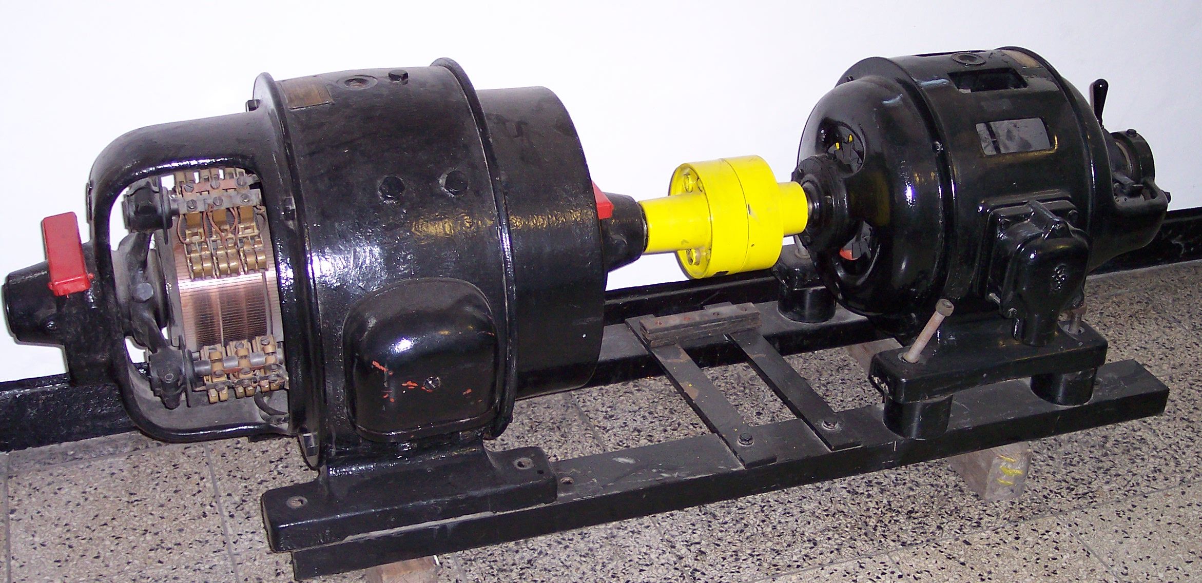
Electric power in the motor is converted into a mechanical one, causing it to rotate, and some of this power is expended on heating the conductor. The design of the electric DC motor includes an armature and an inductor that separate the air gaps. The inductor, consisting of additional and main poles, and the frame, is designed to create magnetic field. Anchor, assembled from separate sheets, winding working and collector, thanks to which the direct current is supplied to working winding, form a magnetic system. The collector is a cylinder, mounted on the shaft of the engine, assembled from copper plates isolated from each other. To its protrusions the ends of the armature winding are soldered. The current from the collector is removed by means of brushes fixed in a certain position in the brush holders, thereby ensuring the necessary pressure on the collector surface. Brushes with engine housing are connected by a traverse.
Brushes, in the course of work, glide over the surface of the rotating manifold, passing from one plate to the other. In this case, in parallel armature winding sections, a current change occurs (when the brush short-circuits the turn). This process is called commutation.
Under the influence of its magnetic field, an EMF of self-induction occurs in the closed section of the winding, causing an additional current that distributes the current unevenly on the brush surface, which leads to sparking.
Rotation frequency - one of its most important characteristics. It can be regulated in three ways: by changing the excitation flux, changing the magnitude of the applied voltage to the motor, changing the resistance in the anchor chain.
The first two methods are encountered much more often than the third, because of its inefficiency. The excitation current is regulated by any device, which is capable of changing the active resistance (for example, a rheostat). Adjustment by means of voltage variation requires the presence of a direct current source: a converter or a generator. Such regulation is used in all industrial electric drives.
Braking of an electric DC motor
For braking of electric drives with DPT there are also three options: Inhibition by opposing, dynamic and recuperative. The first is due to a change in the polarity of the current in the armature winding and the voltage. The second is due to the short-circuiting (through the resistor) of the armature winding. The electric motor thus works as a generator, converting it into electrical energy stored by it, which is released in the form of heat. This braking is accompanied by an instant engine stop.
The latter occurs if the electric motor, included in the network, rotates at a speed that is higher than the idle speed. The EMF of the motor winding in this case exceeds the value of the voltage i in the network, which leads to a change in the opposite direction of the current in the motor winding, i.e. The engine gives energy to the network, switching to the generator mode. At the same time there is a braking torque on the shaft.
Advantages of DC motors
Comparing them with asynchronous motors, it is necessary to note excellent starting qualities, high speed (up to 3000 rpm), and also good adjustment. Of the shortcomings can be noted? Complexity of design, low reliability, high cost and repair and maintenance costs.
Principle of action of DPT
DPT, like any modern motor, operates on the basis of the "Rule of the Left Hand", with which everyone is familiar with the school and Faraday's law. When connecting the current to the lower winding of the armature in one direction, and to the winding of the upper one in the other, the armature starts to rotate, and the conductors laid in its grooves are pushed out by the stator magnetic field or the windings of the DC motor housing. The lower part is pushed to the right, and the upper part is pushed to the left. As a result, the anchor rotates until its parts are exchanged. To achieve continuous rotation, the polarity of the armature winding must be regularly swapped. This is exactly what the collector, switching at the rotation of the armature winding, does. The collector is supplied with a voltage from the source through a pair of pressure brushes made of graphite.
Principal schemes of DPT
The AC motor is connected simply, unlike DPT. Typically, these high and medium power motors have separate terminals in the terminal box (from the winding and the armature). The armature is usually supplied with a full voltage, and on the winding - a current that can be regulated by a rheostat or a voltage variable. From the magnitude of the current present on the excitation winding, the RPM of the AC motor is directly proportional.
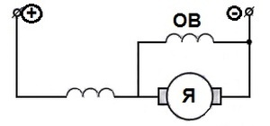
Depending on which DC motor connection scheme is used, the electric motor can be a DC current, divided into self-excited and independent excitation (from a separate source).
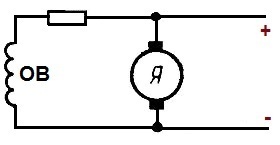
Scheme for connecting a motor with parallel excitation
It is similar to the previous one, but does not have a separate power source.
When you need a large starting current, engines with excitation are used in a series: in city electric transport (trolley buses, trams, electric locomotives).
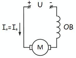
The currents of both windings in this case are the same. Disadvantage - a constant load on the shaft is required, since when it is reduced by 25%, the speed of rotation sharply increases and the engine fails.
There are also motors that are rarely used - with mixed excitation. Their scheme is presented below.
Direct current electric motor with parallel excitation
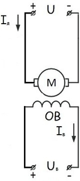
Under the term "excitement" is understood the creation in electric machines The magnetic field, which is necessary to make the engine work. Excitation schemes are several:
- With independent excitation (the winding is powered from an extraneous source).
- DC electric motor with parallel excitation (the power source of the field winding and the armature are connected in parallel) - shunt.
- With sequential excitation (both windings are connected in series) - serial.
- With mixed excitation - compound.
Brushless motors
But, the engine with brushes that wear out quickly and lead to sparking can not be used where high reliability is required, therefore, electric motors (electric bicycles, scooters, motorcycles and electric cars) have the most application of brushless electric motors. They are characterized by high efficiency, low cost, good specific capacity, long service life, small size, quiet operation.
The work of this engine is based on the interaction of the magnetic fields of the electromagnet and the permanent one. When the window is 21 century, and around full of powerful and inexpensive conductors, it is logical to replace the mechanical inverter with a digital one, add a sensor for the position of the rotor, decides at which moment a specific coil needs to apply voltage, and get a brushless DC motor. As a sensor is more often used Hall sensor.
Since brushes are removed in this engine, it does not need regular maintenance. The DC motor is controlled by means of the control unit, which allows to change the speed of the motor shaft rotation, to stabilize the revolutions at a certain level (regardless of the load on the shaft).
There is a control unit consisting of several units:
- Systems of pulse-phase control of NRFU.
- The Regulator
- Protection.
Where to buy the electric motor
Many companies with world names produce today a 220 V DC electric motor. You can buy it in online stores, the managers of which will provide comprehensive online information regarding the chosen model. A large selection of models of such engines on the site http://www.aliexpress.com/w/wholesale-brushless-dc-motor.html, in the catalog of which it is possible to get acquainted with the cost of models, their description, etc. Even if there is no interesting engine in the catalog, you can order its delivery.
Collector AC motors are widely used as power units for household appliances, hand power tools, electrical equipment for cars, and automation systems. The circuit of connection of the collector motor of an alternating current, and also its device remind the scheme and the device of the electric motor of a direct current with consecutive excitation.
The field of application of such motors is due to their compactness, low weight, ease of operation, relatively low cost. The most demanded in this production segment are low-power electric motors with high speed.
- Simplified wiring diagram
- Engine management
- Advantages and disadvantages
- Typical malfunctions
Features of the design and principle of operation
In fact, the AC collector motor is a fairly specific device that has all the advantages of a DC machine and, therefore, has similar characteristics. The difference between these motors is that the AC motor stator housing for reducing eddy current losses is made from separate electrical steel sheets. The excitation windings of the alternating current machine are connected in series to optimize the operation in the domestic 220v network.
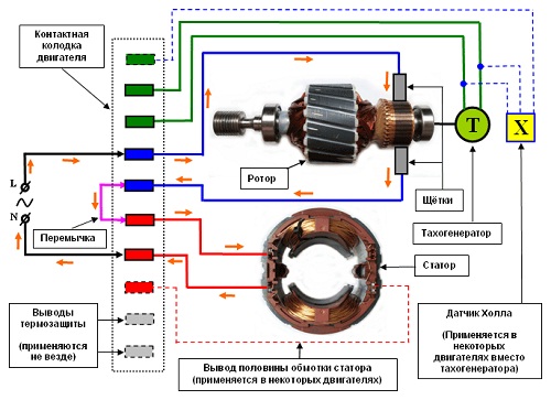
They can be either single-phase or three-phase; thanks to the ability to work from a constant and alternating current are also called universal. In addition to the stator and rotor, the structure includes a brush-collector mechanism and a tachogenerator. Rotation of the rotor in the collector motor results from the interaction of the armature current and the magnetic flux of the excitation winding. Through the brushes, the current is fed to a collector assembled from trapezoidal sections and is one of the rotor assemblies connected in series with the stator windings.
In general, the principle of operation of the collector motor of alternating current can be visually demonstrated using the experience known from school with the rotation of the frame placed between the poles of the magnetic field. If a current flows through the frame, it starts to rotate under the action of dynamic forces. The direction of movement of the frame does not change when changing the direction of current flow in it.
Sequential connection of the field windings gives a large maximum torque, but there are large idling speeds, which can lead to premature failure of the mechanism.
Simplified wiring diagram
A typical circuit for connecting an AC collector motor can provide up to ten output contacts on the contact strip. The current from the phase L flows to one of the brushes, then it is transferred to the collector and the armature winding, after which the second brush and the jumper goes to the stator windings and goes to neutral N. This method of connection does not include the reverse of the motor due to the consequent connection of the windings leading to simultaneous replacement of the poles of magnetic fields and as a result the moment always has one direction.
The direction of rotation in this case can be changed only by changing the places of the output of the windings on the contact strip. The engine can be "directly connected" only with the stator and rotor connections connected (via a brush-collector mechanism). The half winding output is used to turn on the second speed. It should be remembered that with this connection, the motor runs at full power from the moment it is turned on, so it can be operated for no more than 15 seconds.
Engine management
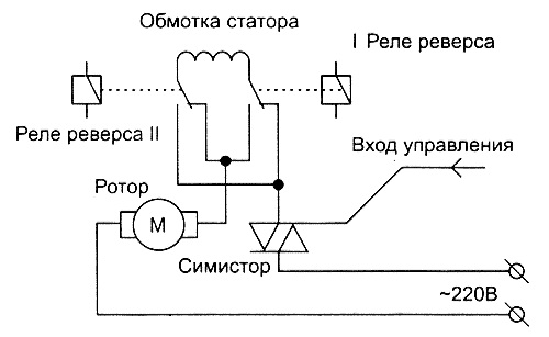
In practice, engines with different ways regulation of work. The collector motor can be controlled using electronic scheme, in which the role of the regulating element is performed by a triac that "passes" the specified voltage to the motor. The triac works like a quick-wrench, on the gate of which control pulses come and open it at a given moment.
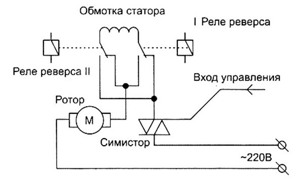
In circuits using a triac, the principle of action based on the full-wave phase control is implemented, in which the magnitude of the voltage applied to the motor is tied to pulses arriving at the control electrode. The frequency of rotation of the armature is directly proportional to the voltage applied to the windings. The operation principle of the collector motor control circuit is described in simplified terms by the following items:
- the electronic circuit sends a signal to the gate of the triac;
- the gate opens, current flows through the stator windings, giving the motor armature M rotation;
- tachogenerator converts into instantaneous electrical signals instantaneous values of the rotational speed, as a result, feedback is generated with the control pulses;
- as a result, the rotor rotates evenly under any load;
- the reverse of the electric motor is carried out by means of relays R1 and R
In addition to the triac, there is a phase-pulse thyristor circuit management.
Advantages and disadvantages
The undeniable advantages of such machines include:
- compact dimensions;
- increased starting torque; "Universality" - work on alternating and constant stress;
- speed and independence of the network frequency;
- soft speed control in a wide range by varying the supply voltage.
- reducing the longevity of the mechanism;
- sparking between and collector and brushes;
- increased noise level;
- a large number of collector elements.
Typical malfunctions
The most attention to self requires a brush-collector mechanism, in which sparking is observed even with the operation of the new engine. The used brushes should be replaced to prevent more serious malfunctions: overheating of the collector sipes, deformation and peeling. In addition, it can occur interturn closure winding of the armature or stator, as a result of which there is a significant fall of the magnetic field or a strong arcing of the collector-brush transition.
Avoid the premature failure of the universal collector motor can be the competent operation of the device and the professionalism of the manufacturer in the process of assembling the product.
Due to its compact dimensions, the collector motor is widely used in the construction of hand power tools. It is successfully used instead of capacitor single-phase asynchronous. Mass application of collector motors is due to their high power, ease of operation and maintenance. Regardless of external differences and types of fasteners, they all have the same operating principle.
The device and the principle of operation
First of all, this is single-phase electric motor, where there is a consecutive excitation of the windings. For its operation, alternating or direct current can be used. For this reason, the collector motor is considered universal.
Most of these motors have in their design the basic elements in the form of a stator along with the excitation winding, as well as the rotor and two brushes as a sliding contact. A large role in the entire design is assigned to the tachogenerator. Its magnetic rotor is fixed at the end of the rotor shaft, and the coil is fixed by means of a locking ring or cover.
All the components of the electric motor are combined in a common design. They are connected by two aluminum covers, which directly form the motor housing. To output the contacts present in all elements, a terminal block is used, which makes it easy to include them in the general electrical circuit. To operate the belt drive, a pulley is pressed onto the rotor shaft.
Connection and management
The work of this type of engines is based on the interacting fields present in the stator and rotor when electric current passes through them. The collector motor has a series circuit, through which windings are connected. The terminal block allows you to use up to ten contacts, increasing the number of connection options.
The simplest connection can be made, knowing only the location of the leads in the stator and brushes. With a normal connection, electrical protection means and devices are installed to limit the current. Therefore, direct connection from the network should be no more than 15 seconds.
The collector motor is controlled by a special electronic circuit. In this scheme, all power adjustment is performed by supplying voltage to the motor in the required quantity and connected in series with it.
1. Application of collector motors in washing machines Collector motors have been widely used not only in power tools (drills, screwdrivers, grinders, etc.), small household appliances (mixers, blenders, juicers, etc.), but also in washing machines in quality of the drum drive motor. Collector engines are equipped with the majority (about 85%) of all household washing machines. These engines have already been used in many washing machines since the mid-90s and have been completely supplanted over time.
Collector motors are more compact, powerful and easy to operate. This explains their so mass use. Washing machines use collector motors of such brands as: INDESCO, WELLING, C.E.S.E.T., SELNI, SOLE, FHP, ACC. Outwardly, they are slightly different from each other, they can have different power, the type of attachment, but the principle of their work is quite the same.
2. A collector motor device for a washing machine
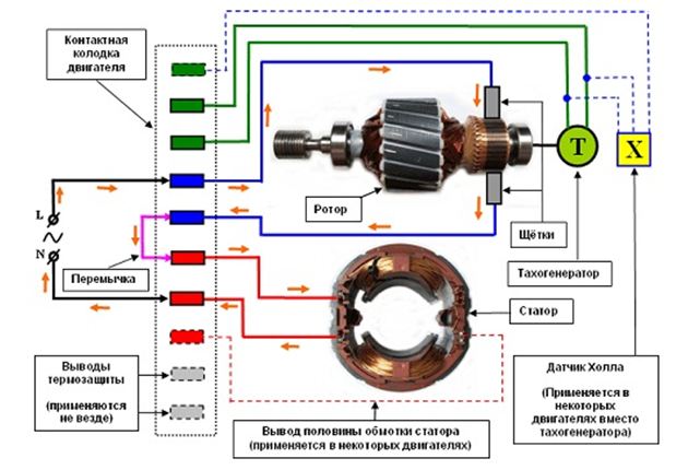
1. The stator 2. Rotor collector 3. Brush (always use two brushes, the second in the figure is not visible) 4. Magnetic rotor of tachogenerator 5. Coil (winding) tachogenerator 6. Tachogenerator locking lid 7. Engine terminal block 8. Pulley 9. Aluminum housing Fig. 2 |
Collector motor - this single-phase motor with a series of excitation of the windings, designed for operation from an AC or DC network. Therefore, it is also called the universal collector motor (DCM). Most of the collector motors used in washing machines have the design and appearance presented on (Fig. 2) To further understand how the collector motor works, let's look at the device of each of its main nodes. |
2.1 Rotor (anchor)
 Fig. 3 |
Rotor (anchor) - rotating (movable) part of the engine (Fig.3). A core is installed on the steel shaft, which is made of electrotechnical steel plates to reduce eddy currents. In the grooves of the core are placed the same branches of the winding, the terminals of which are attached to the contact copper plates (lamellae) forming the collector of the rotor. On the rotor collector, on average, there may be 36 lamellae located on the insulator and separated by a gap. To ensure the sliding of the rotor, its bearings are pressed onto its shaft, the supports of which are the engine cover. Also, a pulley with molded grooves for the belt is pressed onto the rotor shaft, and on the opposite end side of the shaft there is a threaded hole into which the magnetic rotor of the tachometer is screwed. |
2.2 Stator
| Stator - fixed part of the engine (Fig.4) . To reduce the eddy currents, the stator core is made of electrical steel set-up plates forming a frame on which two equal winding sections are connected in series. The stator almost always has only two leads of both winding sections. But in some engines the so-called stator winding sectioning and there is additionally a third terminal between the sections. This is usually done because when the DC motor is running, the inductive resistance of the windings has less DC resistance and the current in the windings is higher, therefore both winding sections are used, and when working on alternating current only one section is switched on, since to the alternating current the inductive resistance of the winding exerts more resistance and the current in the winding is less. In the universal collector engines of washing machines the same principle is applied, only sectioning of the stator winding is necessary to increase the rotational speed of the rotor of the motor. When a certain rotational speed of the rotor is reached, the electric circuit of the motor is switched in such a way that one section of the stator winding is switched on. As a result, the inductive resistance is reduced and the engine is gaining even greater revs. This is necessary at the stage of pressing (centrifugation) in the washing machine. The average output of the stator winding sections is not used in all collector motors. |  Fig. 4 Stator of the collector motor (view from the end) |
To protect the motor from overheating and current overloads, sequentially through the stator winding include thermal protection with self-healing bimetallic contacts (thermal protection is not shown in the figure). Sometimes thermal protection contacts are output to the motor terminal block.
2.3 Brush
 Fig. 5 |
Brush is a sliding contact, is a link electrical circuit providing electrical connection the rotor chain with the stator circuit. The brush is attached to the motor housing and at a certain angle abuts the collector sipes. At least a pair of brushes are used, which forms the so-called brush-collector unit. The working part of the brush is a graphite bar with a low electrical resistivity and a low coefficient of friction. Graphite bar has a flexible copper or steel flagellum with a soldered contact terminal. For pressing the bar to the collector, a spring is used. The entire structure is enclosed in an insulator and attached to the engine casing. During operation of the engine, the brushes are rubbed off due to friction against the collector, therefore they are considered consumables. |
| (from other Greek, τάχος - speed, speed and generator) is a DC or AC measuring generator designed to convert the instantaneous frequency (angular velocity) of the shaft rotation into a proportional electrical signal. The tachogenerator is designed to control the rotation speed of the rotor of the collector motor. The rotor of the tachogenerator is fixed directly to the motor rotor and, when rotating in the coil winding of the tachogenerator, a proportional electromotive force (EMF) is induced according to the law of mutual induction. The value of the alternating voltage is read from the coil's terminals and processed by an electronic circuit, and the latter ultimately determines and controls the necessary, constant rotational speed of the motor rotor. The same principle of operation and design have tachogenerators used in single-phase and three-phase asynchronous motors washing machines. |
 Fig. 6 |
At the collector motors of washing machines, there can be from 6 to 10 contacts in use on the terminal block. The figure shows all the maximum 10 contacts and all possible options for connecting the engine nodes.
Knowing the device, the principle of operation and the standard scheme for connecting the collector motor, it is easy to start any engine directly from the mains without using an electronic control circuit and for this you do not need to remember the location of the winding leads on the terminal block of each motor brand. For this, it is enough just to determine the conclusions of the stator windings and brushes and connect them according to the scheme in the figure below.
The order of the contacts of the terminal block of the collector motor of the washing machine is chosen arbitrarily.
Fig. 7
On the diagram, orange arrows indicate the direction of the current along the conductors and windings of the engine. From phase (L), current flows through one of the brushes to the collector, passes through the turns of the winding of the rotor and exits through another brush and through the jumper current passes successively through the windings of both stator sections to the neutral (N).
This type of motor, regardless of the polarity of the applied voltage, rotates in one direction, because due to the serial connection of the stator and rotor windings, the change of the poles of their magnetic fields occurs simultaneously and the resultant moment remains directed to one side.
In order for the engine to start rotating in the opposite direction, it is only necessary to change the sequence of commutation of the windings.
The dashed line indicates the elements and terminals that are not involved in all engines. For example, the Hall sensor, the thermal protection leads and the output of the half of the stator winding. When starting the collector motor directly, only the stator and rotor windings (via brushes) are connected.
Attention! The presented circuit of connection of the collector motor directly, does not have means of electric protection against short circuit and current limiting devices. With such a connection from the household network, the engine develops full power, so do not allow a long direct inclusion.
4. Control of the collector motor in the washing machine
The principle of operation of electronic circuits in which a triac is used is based on full-wave phase control. On the graph (Fig. 9) It is shown how the voltage of the motor voltage varies depending on the pulses coming from the microcontroller to the control electrode of the triac.
Fig.9 Change in the value of the supply voltage as a function of the phase of the incoming control pulses
Thus, it can be noted that the rotational speed of the motor rotor directly depends on the voltage applied to the motor windings.
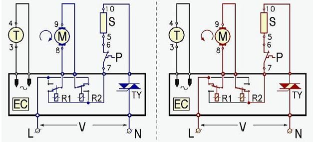
Below, on (Fig.10)fragments of the conditional electrical circuit connection of a collector motor with a tachogenerator to an electronic the control unit (EC).
The general principle of the control circuit of the collector motor is as follows. The control signal from the electronic circuit goes to the gate triac (TY), thereby opening it and a current flows through the windings of the motor, which leads to rotation rotor (M) engine. At the same time, tachogenerator (P) transmits the instantaneous value of rotational speed of the rotor shaft to a proportional electrical signal. By signals from the tachogenerator, feedback is created with the signals of the control pulses delivered to the gate of the triac. This ensures uniform operation and rotation speed of the motor rotor under all load conditions, whereupon the drum in the washing machines rotates evenly. To implement the reversible rotation engine special relay R1 and R2 , commuting windings of the motor.
Fig. 10 Changing the motor rotation direction
In some washing machines, the collector motor operates on direct current. For this, in the control circuit, after the triac, an AC rectifier built on diodes ("diode bridge") is installed. The work of the DC motor collector increases its efficiency and maximum torque.
5. Advantages and disadvantages of universal collector motors
Advantages include: compact dimensions, large starting torque, high speed and lack of connection to the network frequency, the ability to smoothly control the speed (torque) in a very wide range - from zero to the nominal value - by changing the supply voltage, the possibility of applying the work both on a constant and alternating current.Disadvantages - the presence of a collector-brush assembly and in connection with this: relatively low reliability (service life), sparking occurs between brushes and the collector due to commutation, high noise level, a large number of parts of the collector.
6. Malfunctions of the collector motors
The most vulnerable part of the engine is the collector-brush assembly. Even in a working engine, there is sparkling between the brushes and the collector, which heats its lamellas quite strongly. When the brushes wear to the limit and due to their poor pressure against the collector, arcing sometimes reaches the culmination moment representing the electric arc. In this case, the collector lamellas are strongly overheated and sometimes exfoliate from the insulator, forming an unevenness, after which, even replacing worn brushes, the engine will work with strong sparking, which will lead to failure.Sometimes the interturn closure of the winding of the rotor or stator occurs (much less often), which is also manifested in the strong sparking of the collector-brush assembly (due to the increased current) or the weakening of the magnetic field of the engine, in which the rotor of the engine does not develop a full torque.
As we said above, brushes in the collector motors are rubbed against the collector with time. Therefore, most of the work on engine repair is to replace the brushes.
It is worth noting that the reliability of the collector motor largely depends on how well and competently the manufacturers are approaching the technological process of its manufacturing and assembly.
Material prepared by the service department "Aqualux"
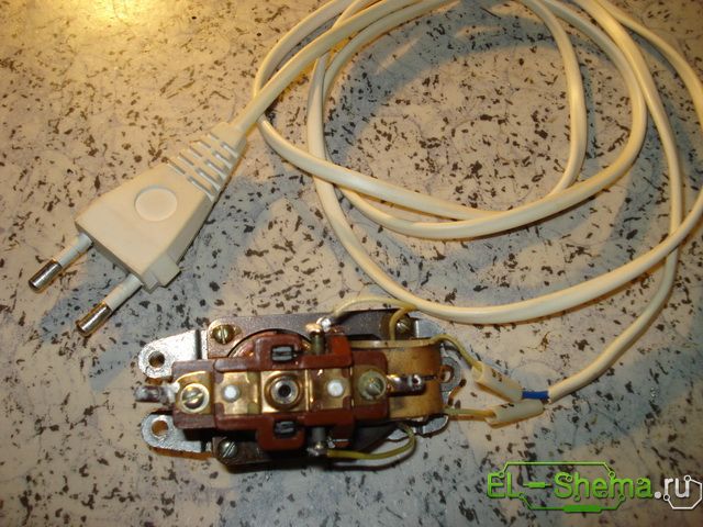
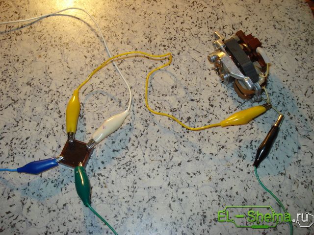
It became necessary to connect a universal collector motor. At first glance, there are no problems. Engine working, previously stood in the appropriate device and performed its intended function, that is, it was already connected. But the fact is that it was decided to use it in a completely different device. Conditions, possibilities of operation and requirements, both to his work, and to the service life have changed. After all, the mechanism in which it was supposed to re-engage the electric motor, will have to be assembled just for it. What to do with the existing harness? Can and most importantly, do you need to change something in it? In this particular case, this is an electric motor from an electric shaver.
The existing harness consists of capacitors and chokes designed to perform solely the functions of an interference suppression filter.
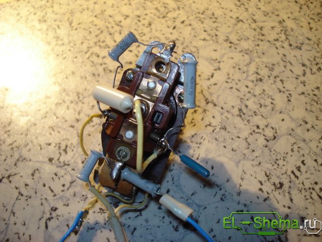
They do not influence the engine directly. It is known that a universal collector electric motor works equally well both on a constant and alternating current. Accordingly, without further ado, with the existing resistance of the stator winding sections (more than 800 ohms) plus the armature resistance (360 ohms), the connection can be made according to the following scheme:
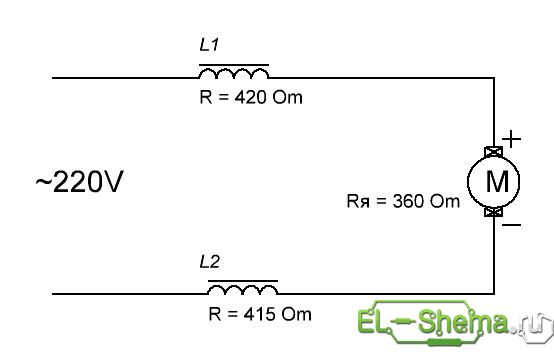
That was successfully tested.
However, at a constant current a little better. First, the efficiency of the motor with AC current is lower, secondly the service life of the brushes, the collector and the whole machine is shorter. The connection scheme will be as follows.
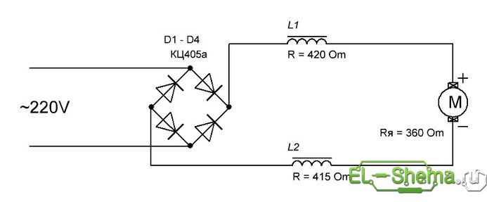
This version of the scheme was tested.
The sparks of the collector brushes became noticeably smaller. I decided to stop at this, but I was advised that when using this DC motor, a capacitor should be added after the diode bridge.
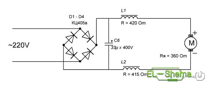
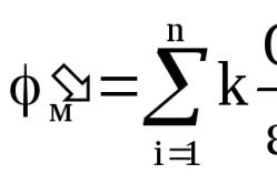
The capacitance of the capacitor was originally calculated from the formula, which seemed suitable for the given case. When connecting a capacitor with a design capacity of 200 mkf, the engine roared like a small electric drill, which made it necessary to reduce the capacity. The formula for calculating that did not justify itself, I do not see "sharing" the meaning.
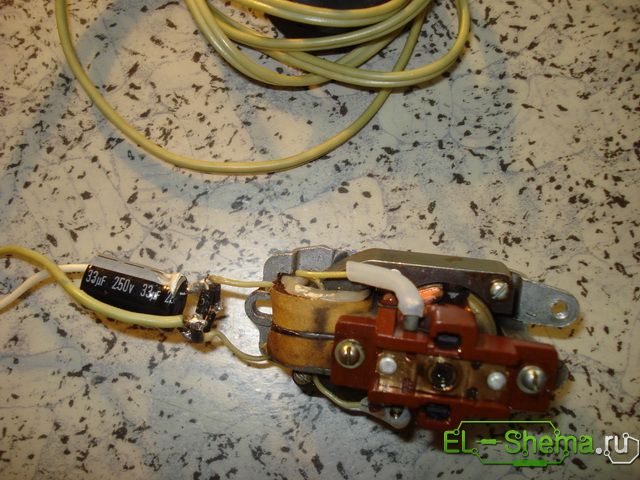
He stopped at a capacitor 33mkf x 250V and a diode bridge of diodes 1N4007 (as more compact). The work of the electric motor is satisfied.
Video of work of the electric motor
Nothing unusual, but it's really better to see than to hear (in this case, read) how he "buzzes" there, how he "sparkles" there. I wish you successful experiments, Babay.