Antipyretics for children are prescribed by a pediatrician. But there are situations of emergency care for fever, when the child needs to give the medicine immediately. Then the parents take responsibility and apply antipyretic drugs. What is allowed to give to infants? How can you bring down the temperature in older children? Which medications are the safest?
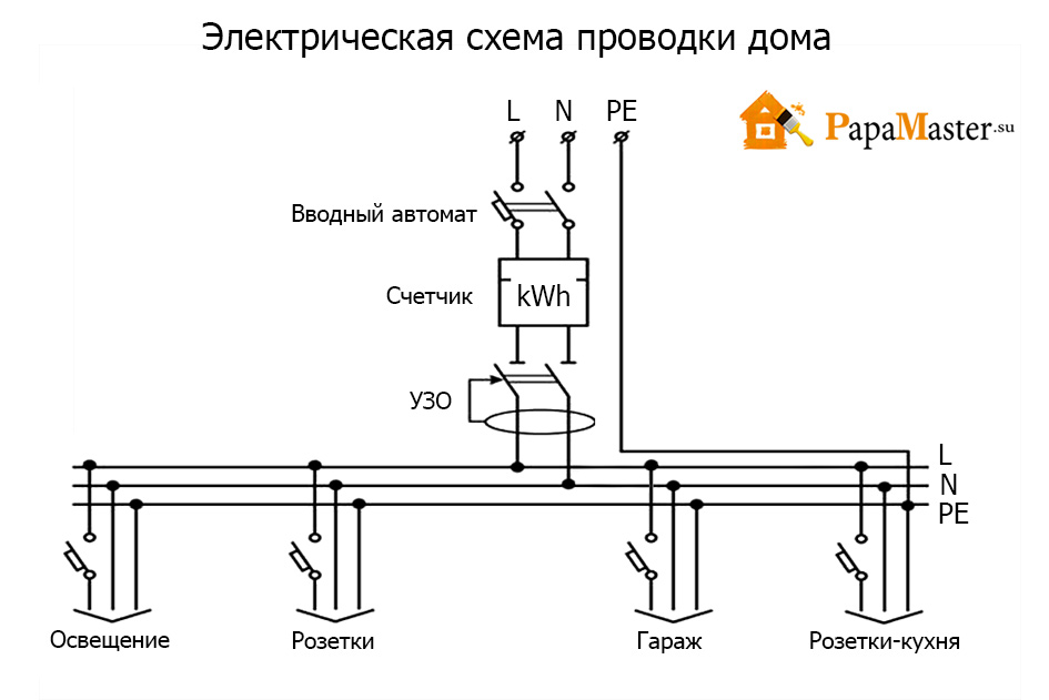
With electricity, jokes are bad - this has been taught to us since childhood. But life forces you to adapt, and if you have certain knowledge, you can conduct the wiring in the house yourself. First of all you have to identify the place where the distribution board will be located. Most often for him choose a dry warm room, fixing it at an altitude of about one and a half meters. The shield is the key element and acts in the circuit as the initial link. After installation, you can begin planning and marking out places for sockets, switches, and other electrical appliances.
Scheme of installation of electrical wiring in a private house with their own hands
While preparing the wiring diagram of wiring in a private house, one must proceed from one's own needs. That is, if the standard assumes the presence of two outlets per room, and you need three, then naturally it is necessary to stop at a more convenient option for you.
Schemes come in two types: electrical and installation. The first one helps to calculate the number of devices consumed by the current by selecting an acceptable connection option. The second is actually a mapping electrical circuit on practice. It marks the place of installation of devices, the quantity connecting cable and other consumables.
Moments to pay attention to
Despite the fact that the basic scheme does not exist, and each is developed taking into account individual characteristics, there are important recommendations that are not recommended to be neglected.
Devices with a large electricity consumption (boiler, electric stove, refrigerator, washing machine) are preferably connected with the possibility of grounding. For this purpose, a special three-wire wire is used ("ground", "phase" and "zero"). A cable of this type is recommended to be used in places with high humidity, for example, in the bathroom.
To implement the wiring diagram in a private house, the best option is a cable with a cross section of 2.5 mm. It is ideal for sockets and luminaires, although for the latter one can take a wire with a cross section of 1.5 mm, but the savings will be negligible.
It is very important not to overload the sockets. When connecting several, the permissible total power is 4.6 kW. Also, every large household appliance should have an individual outlet.
Stages of self-assembly wiring
Installation work begins with the marking of the walls. They put a way of laying the cable and places where the outlets and switches will be located. The main rule that will help to avoid the "headache" in the future, is that the wires are placed only in a horizontal or vertical position. There should not be any diagonals to save cable. The turns are performed strictly at an angle of 90 °. From the ceiling, an indentation of at least 20 cm is made.
As far as sockets and switches are concerned, most often spores originate with respect to the height of their location. The switches are preferably located on the side where the handle is located. There are two standard heights for switches - 50-80 cm and 150 cm from the floor. The second option is inherent in buildings of the Soviet type, and in new homes the preference is given to the first option. It is better to immediately place the location of the switches on the electrical wiring diagram in a private house. This applies to the places for the outlets. Regarding their standard is absent, but according to the unspoken rule they are placed either at a distance of 80 cm from the floor, or within 20-30 cm, almost immediately above the skirting board. The main point of choosing a place for the outlet is convenience of use.
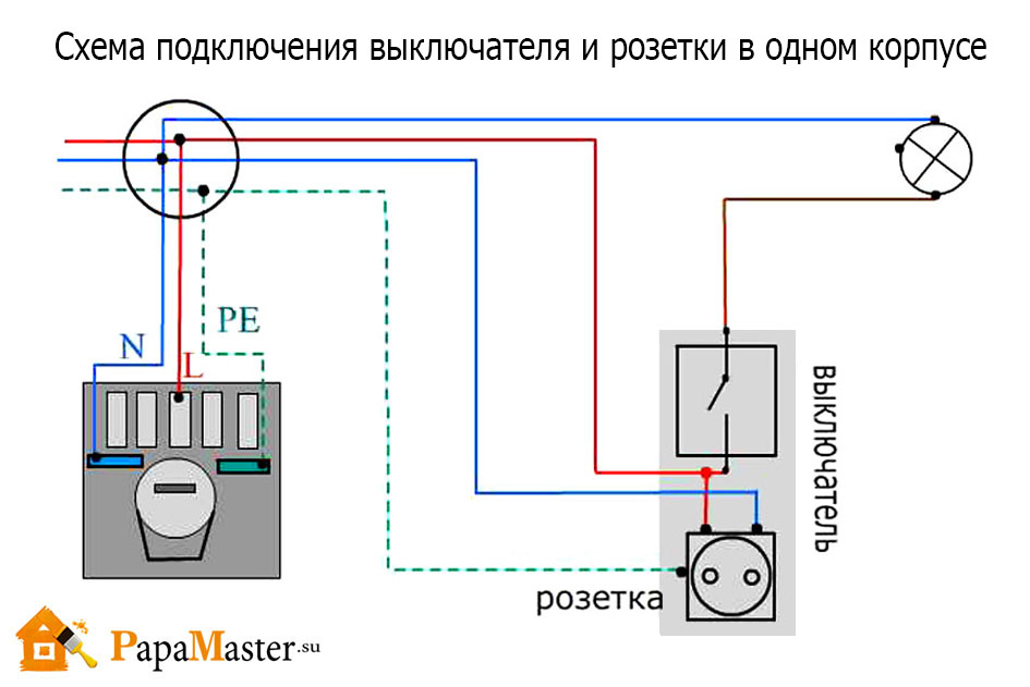 circuit diagram of the switch and socket
At the next stage, the channels and openings under the boxes are shrouded in the walls. The cable in the channel is fixed with gypsum, it dries quickly and provides a reliable fixation. On the plaster sit and plastic boxes, which are mounted switches and sockets. Between each other, the wires are twisted, and the contact area must be maximal. These places are to be isolated.
|
Installation of electricians in a cottage or in a turn-key house, as a rule, is divided into 2 stages: Stages of internal installation works for the electric cottageStage 1. Draft worksThe draft works include:
|
Read, also |
The final stroke of the first stage is the mandatory testing of cable routes. The Test Report and the Hidden Work Act are compiled on the test result.

The best option is to perform the design before wiring. The project allows to take into account all wishes of the Customer concerning electricians andbring them in line with applicable rules and regulations. After that, the necessary electrical equipment is selected, the distance and the cross section are calculated cable lines, and after all this is done wiring.
The installation of the electrician, which is carried out under the project, excludes erroneous actions, and the Customer is guaranteed to receive a safe and efficiently functioning electricity supply that fully meets his wishes. Also, most often, designing leads to a budget saving on the creation of the system.
If the design is not carried out, then at least calculate the loads. This will not affect the cost of installation and the electrical system as a whole. After the end of this calculation, the selection of the cable section can be made on the basis of the table.
|
S of the conductor cross-section, mm2 |
Power supply voltage U = 220V |
Power supply voltage U = 380V |
||
|
I, A |
P, kW |
I, A |
P, kW |
|
|
1.5 |
19 |
16 |
11 |
|
|
2.5 |
27 |
25 |
17 |
|
|
4.0 |
38 |
30 |
20 |
|
|
6.0 |
46 |
10 |
40 |
26 |
|
10.0 |
70 |
15 |
50 |
34 |
|
16.0 |
85 |
19 |
75 |
50 |
|
25.0 |
115 |
25 |
90 |
60 |
|
35.0 |
135 |
30 |
115 |
80 |
|
50.0 |
175 |
39 |
145 |
96 |
|
70.0 |
215 |
47 |
180 |
119 |
|
95.0 |
260 |
57 |
220 |
145 |
|
120.0 |
300 |
67 |
260 |
171 |
Stage 2. Installation of terminal electrical devices
This stage is, as a rule, after finishing the premises. It carries out the installation:
- Switches
- Svetilnikov
- Chandelier
- Color
- Other installation electrical equipment
It is necessary to know that the laying of cable routes is desirable before the finishing works. This significantly reducesthe final the price of the installed electrical system.
Cost of installation of electricians in cottages on a turn-key basis - the price for work
| Name of installation works in the house | Unit. Meas. |
Price for work (rub.) |
Assembly and installation of switchboards |
||
| Assembly switchboard for 18 modules | pC. | 4 320
|
| Assembling the switchboard for 24 modules | pC. | 5 760 |
| Assembling the switchboard for 36 modules | pC. | 8 640 |
| Assembling the switchboard for 48 modules |
pC. |
11 520 |
| Assembling the switchboard for 54 modules | pC. | 12 960 |
| Assembling the switchboard for 72 modules |
pC. | 17 280 |
| Assembling the switchboard for 120 modules | pC. | 28 800 |
| Installation and connection of a switchboard for 18 modules |
pC. | 2 610 |
| Installation and connection of a switchboard for 24 modules | pC. | 3 460 |
| Installation and connection of a switchboard for 36 modules | pC. | 5 190 |
| Installation and connection of a switchboard for 48 modules | pC. | 6 920 |
| Installation and connection of a switchboard for 54 modules | pC. | 7 780 |
| Installation and connection of the switchboard for 72 modules | pC. | 10 370 |
| Installation and connection of a switchboard for 120 modules | pC. | 17 280 |
Laying of electric wiring |
||
| Cable laying in corrugated HDPE pipe | m. | from 110 |
| Tightening of cable in corrugated HDPE pipe |
m. | 28 |
| Cable laying in steel pipe | m. | from 260 |
| Tightening of the cable into a steel pipe (with machining of a pipe) | m. | 62 |
| Mounting the cable duct |
m. |
160
|
| Cable laying in cable duct | m. | 127 |
| Installation of jigs |
pC. | 250 |
| Wiring in boxes |
pC. |
380 |
| Mounting and connection of the motion sensor | pC. | 900 |
| Installation of drawer boxes |
pC. | 420 |
| Mounting the floor hatch |
pC. | 1 800 |
| Installation of retro cable |
m. | from 120 |
| Installation of insulators | pC. | from 22 |
| Cable laying in a trench | m. | 120 |
| Connecting the input cable |
pC. | 4 000 |
| Installation of the ground loop | set | 18 200 |
Testing of cable routes |
||
| Cable up to 100 m. |
pC. | 2 300
|
| Cable up to 500 m. | pC. | 4 200
|
| Cable up to 1 000 m. | pC. | 7 800 |
| Cable up to 1 500 m. |
pC. | 9 000
|
Stroblenie |
||
| Penoblock |
m. | 330 |
| Brick | m. | 350 |
| Concrete | m. | 500 |
| Monolith | m. | 600 |
Installation works of the second stage |
||
| Installation and connection of electrical outlets | pC. | 480 |
| Installation and connection of overhead electrical outlets | pC. | 480 |
| Installation and connection of single-pole / single-key switch mechanisms | pC. | 400 |
| Installation and connection of unipolar / single-key overhead circuit breakers | pC. | 400 |
| Installation and connection of single-pole / double-switch mechanisms | pC. | 450 |
| Installation and wiring of single-pole / two-switch overhead circuit breakers | pC. | 450 |
| Installation and connection of single-pole / one-button switches | pC. | 730 |
| Installation and wiring of single-pole / one-button switches | pC. | 730 |
| Installation and connection of wall brackets | pC. | 710 |
| Installation and connection of ceiling lighting fixtures | pC. | 850 |
| Installation and connection of chandeliers (up to 3 kg.) | pC. | 2 800 |
| Installation and connection of recessed lighting fixtures | pC. | 530 |
| Installation and connection of mechanisms of low-voltage sockets | pC. | 690 |
| Installation and connection of overhead low-voltage sockets | pC. | 690 |
| Installation and connection of sensors of the OPS system | pC. | 500 |
The resulted price-list is not complete. It lists the most frequently ordered work. The full price or the total cost of production of installation works on the electrician in your cottage, you can request by contacting our specialists:
FROM electrical installation works in the private sector in our country is rather bad than good. For most mountain electricians, protecting a person from electric shock, and property from a fire, to great regret does not mean anything. At the same time, the impression is that ordinary users were skipping physics lessons at school and completely do not understand what is electricity. But they very well believe in marketing tricks and happily attack "branded" automation, rejecting any other.
I propose step by step to understand all the issues of electricity a country house on the example of single-phase input. Also this guide can be applied to the use in the apartment. Immediately, I note that my solution of particular nodes is the optimal balance between functionality and price, but without compromising security!
I hope there is no need to retell a full course of physics and explain what an alternating electric current is. We also omit the moments how this electric current appeared on the power station and through the step-up transformer got into the power line. I will only note the important nuance that the entire electricity supply system in Russia is three-phase. Single-phase voltage 220 volts in your outlet is only a phase voltage in one of the three phases. And the line voltage will be 380 volts. This circumstance should be taken into account in view of such a phenomenon as "phase skewing", which nevertheless is relevant only with the old wiring, not designed for modern loads.
2. So, the step-down transformer in the SNT. A high voltage of 10 kV comes on three wires. Further diverges 4 wires (3 phase and one zero conductor) through SNT. In the photo you see a modern transformer and bends in the form of CIP wires. At the moment, air lines in our SNT are undergoing modernization.
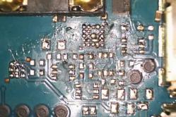
3. With a single-phase input, two conductors are connected to each consumer: phase and zero. In the photo you can see the old aluminum wires on the support nearest to the house. The tap to the house has already been made using a CIP wire. Particular attention is paid to the fact that all air line supports must have a grounding of the zero conductor (right upper photo). This is necessary in order to exclude emergency situations, such as a "zero break". In this case, you should pay special attention to your own grounding in the absence of repeated grounding on the intermediate supports, otherwise in an emergency your own grounding may be unique for the whole village.
4. Closer to the point. The last section of the air line from the nearest post to the building is stretched by the CIP wire, in our case 2х16. Stands for self-supporting insulated wire, it is aluminum with a cross section of 16 mm². For ease of installation and laying in place of the anchorage with the help of special clamps (wire SIP means the installation of the line under tension, at special terminals the nut is not under tension, and also has a rupture thread guaranteeing the necessary tightening force) passes into the VVG section of at least 10 mm² . It is in this form that two wires enter the lead-in shield. In the shield we have an introductory bipolar machine and an overvoltage limiter (always on the final support during air entry), which will protect the network when lightning strikes the phase conductor of the overhead line. It is connected in front of the machine to the phase conductor. Here in the shield there is a connection of the grounding strictly up to the input automaton. We are considering the TN-C-S grounding scheme, since the TT system is still designed for mobile buildings, rather than permanent buildings, and it has its own characteristics for security requirements. The disadvantages of the TN-C-S system with proper installation are not. Even if you go deeper into this topic, if you make a TT, it will be only your final section, while the whole air line from the transformer will be TN-C.
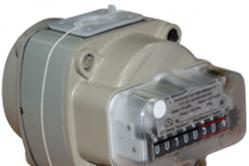
5. Mandatory grounding. Three corners with a wall of 50 mm (steel thickness of 5 mm), 2 meters in length, are driven into the ground by a sledge hammer and welded together in a triangle shape. To the wall of the house there is a steel strip with a width of 40 mm. The last meter to the shield is made with a copper conductor of at least 16 mm². Underestimating the cross-section is absolutely impossible, in case of any accident on the line, your grounding can become the only one for the entire line / street / block. Switching in the shield is as follows. The combined PEN (Protected Earth + Neutral) conductor from the overhead line is divided into two buses on N and PE. After that, the input automaton is switched, next to it is an overvoltage limiter. From the machine line goes to electric meter. Directly into the house goes three-wire copper wire with a cross-section of each conductor of 6 mm². The phase and zero conductors come from a meter grounding from the corresponding bus.
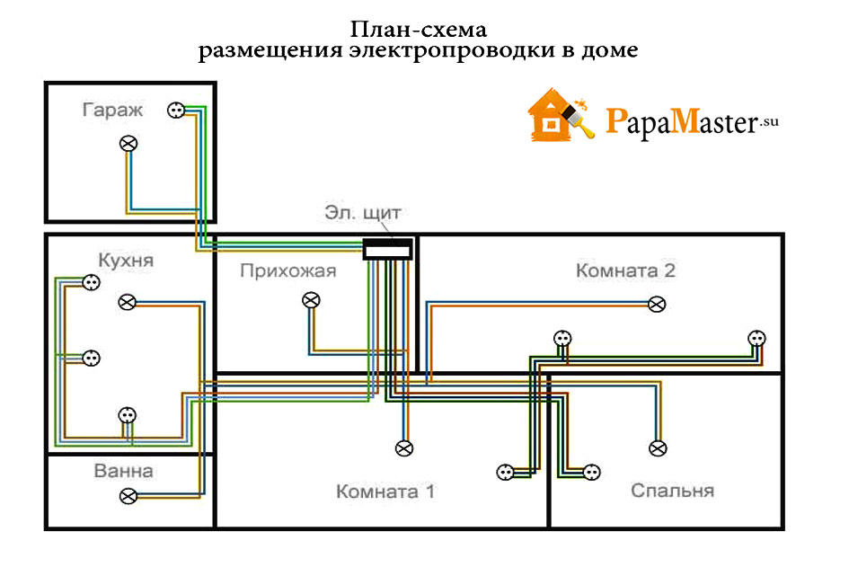
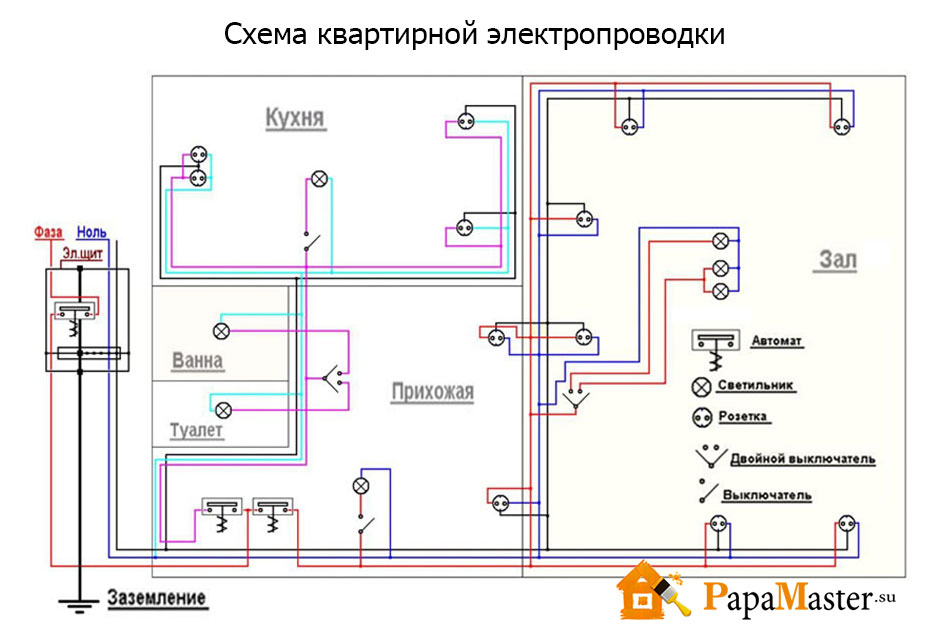
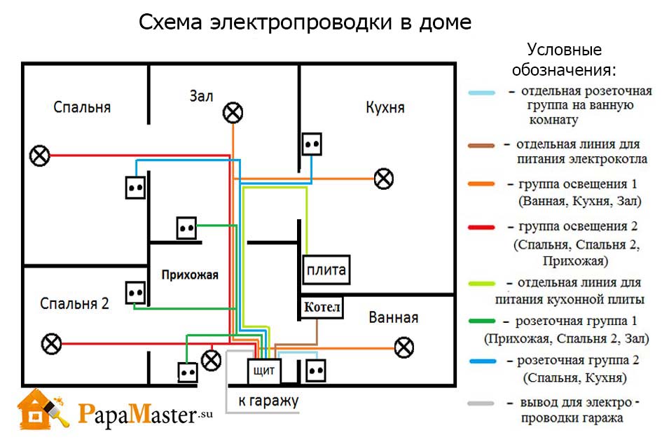
6. We pass to internal wiring at home. I repeat that when designing electrical network the principle of reasonable sufficiency. Of course, it was possible to make 2 times more outlets and to increase the number of lines of force by the same amount, but I think that this is absolutely not necessary. Explanations to the scheme: red squares - junction boxes, yellow circles - lamps. Blue indicates wiring in the screed, red in the walls. Everywhere in the house is used only lED lightening (the total consumption of all lamps included at the same time is below 300 watts). The lighting is powered from the power line to a specific room, I do not see the practical need for separation, besides, it significantly increases the amount of installation work. The diagram shows all existing consumers in the house. If you have questions, ask.
7. So, let's get started. This is a temporary electrician for the period of construction work. We pass to the laying of the lines of force. A total of 10 of them. Some of them will go along the walls, some in the floor in the corrugation.
8. Let's start with the floor lines. We use a NYM cable with a cross-section of 3x2.5 mm² in corrugation (gray corrugation does not burn at all, black does not support combustion and has protection against ultraviolet radiation. In a screed, it is not particularly important what to use, it is not so easy to find a strong gray, and I would trample soft preparatory work). The frequently asked question is why is it not the VVG? In terms of performance, they are completely identical, but the NYM has the advantage of triple insulation, while it has the drawback of a non-UV-resistant shell. Therefore, for open wiring, VVG is preferable. Otherwise, NYM is more convenient, including because of its round shape (a round VVG also exists, but it is extremely difficult to find it). In the corrugation with a diameter of 16 mm round NYM stretches elementary, which is extremely convenient. For memory it is worth to document the lines of laying the lines on the floor, although nowhere else but the door thresholds there is even a theoretical probability that you need to drive something into the concrete floor screed.
9. Corner of the kitchen area. Aerated concrete is simply an excellent material for processing - you can even use a screwdriver to wall the walls. So, we drill the holes for the mounting and junction boxes. Wire in the walls of NONGORYUCHYh grounds is laid in the form in which it is. No corrugations are required. All attention to the trails. Power lines are laid only at right angles. The main line goes along the floor at a height of 20-30 cm, then to the outlets and switches it rises strictly VERTICALLY. Diagonal gasket is prohibited and risky to get into the wire, for example when driving a nail into the wall (and so you know for sure that you can not drive nails exactly under the outlets and above the switches). The cable is fixed to the wall using plastic round staples (two holes are drilled, a bracket is inserted).
10. The floor screed is flooded. The question at what stage to lay the cable on the wall is solely from your personal preferences. Someone first plaster the walls, then make the stroba, lay the cable and seal the stroba back. I prefer to do the wiring before plastering the walls. This method may seem inconvenient because will require increased attention during the plastering works to the points with the mounting boxes (it is necessary to shut them up and then pick them up). Pay attention to the left corner - all the commutations on the pass-through lines of the outlets are not made in the podzheetniki, but in separate junction boxes.
11. I will repeat with the type of wires. NYM is the ideal and versatile cable. The cross-section is selected in accordance with the load. Usually use a cable 3x2, 5 mm². For powerful consumers, such as electric the hob may require a wire with a cross-section of 4 mm². For lighting lines where LEDs are used in my case (the maximum power consumption in the largest room is 80 watts), I use a cable PPPP 2x1.5 mm2 (there is no need for grounding in the lighting network, it has nowhere to connect). In general, the regulations prohibit the use of the PPP because technical conditions allow to understate the cross-section of veins up to 30% in comparison with the standards, and with general economy, this can cause a fire everywhere due to exceeding the permissible load. In my case, my maximum load more than 30 times less than can safely pass the cable with a cross-section of 1.5 mm². Therefore, a larger section is not required, and for installation of the lighting line this cable is most convenient. Yes, please note that for fixed wiring use only a rigid cable with a monobloc. Dashboards and junction boxes are mounted in the wall on a building plaster (alabaster), as the quickest drying solution.
12. Now directly the stage of assembly and installation of power lines. It will take several convenient tools. The topmost is used for crimping the tips multicore cables, for example PV3 (currently replaced by POGV), which are used when assembling the electrical panel. The middle tool is useful for quickly stripping the cable sheath NYM - clamped, cranked, pulled. Below is a simple tool for stripping the final veins, not quite convenient, but for one-time work more than enough.
13. It is still necessary to have such a thing as an indicator screwdriver. There are two varieties of them. The original device with a neon lamp without a power source is able to detect only the phase voltage. This is a simple Chinese device with a power supply has more advanced functionality and allows you to determine not only the phase (it is important to determine the phase can not be touched with the fingers of the screwdriver cap), but also the integrity of the line, as well as the place of wire breakage. On the right is the initial blank for the electrical shield. When switching it is important to distribute everything in such a way that it is intuitively clear where everything is.
14. At once I will note the nuance to which the "experts" must necessarily dig up - the zero conductor should be blue, and I have it black, since in our tree under the name of Moscow there is never anything in stock at the moment when I need it obviously single-phase, a clear catastrophe and the error of confusing zero with the second phase is not here). For switching in the electrical panel I use wire PV3 (it is possible to take a modern POGV) with a cross-section of 6 mm². Also, it will need special NSTHI tips (the tip of the pin bush insulated), they are needed in order to assemble together stranded wire before switching under the screw (veins spread out - there may be bad contact). It is also convenient to use special single-pole and bipolar buses (on the right photo in the background) to connect a number of circuit breakers.
15. Switching in junction boxes is as follows. WAGO 2273 terminals (on the left) are used on conductors with a cross-section of 3x1.5 mm² (why and why - later) and WAGO 222 (right) on conductors with a cross-section of 3x2.5 mm². Always follow the color marking conductors. WAGO 222 series is probably the best option, if there is no desire to work with soldering and crimping.
16. Installation of sockets and switches. I really like Schneider Electric products, the Unica series. Switches on modern standards should be turned down. Switching up is an old school since the time of the knife switches, the inclusion of which up was due to their design. Unica switches are turned down, this is their nominal position.
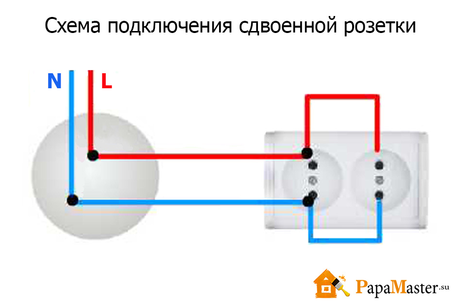
17. Switching double sockets standing next to next. The power cable comes to the terminals of one outlet, and then a branch is made to the adjacent one. The rules of good tone prescribe for the installation of sockets to connect the phase conductor to the right.
18. We return to the electric shield. Just want to pay attention - always take a shield with a very large margin, more than just will not. I kind of made it to the minimum, and almost all 36 positions (3 rows of 12 positions) were occupied. Be sure to leave a supply line of lines of force equal to a minimum of one and a half height of the shield. On the right you can see the first version of switching, and in fact this is the moment when the house was switched from a temporary electrical circuit to a permanent one. In the process, a couple of consumers appeared and the scheme was slightly refined.
So, I tell in detail what, how and why. Go!
A few words about the components of the scute.
A circuit breaker or just an automaton. Provides protection against short circuit, and also provides protection electrical wiring. Hence it contains two releases - electromagnetic and thermal, respectively. The first is triggered in the event of a short circuit on the line, the response time is determined by the time-current characteristic, which in any case is several times higher than the current rating of the machine. Thermal release is a bimetallic plate with different coefficients of thermal expansion and is designed to protect electrical wiring. It is in accordance with the cross-section of the cable and the sockets used that the nominal value of the machine is selected. The most popular mistake to put on a power line with a wire 2,5 mm² automatic to 25A from the calculation that the cable will withstand. No you can not. And the reason is rosettes. Conventional outlets are rated for current up to 16A. Therefore, this should be the value of the machine. And in general as a whole it is better to be reinsured and reduce the denomination of the machine, that is it will be able to protect the wiring from overheating or, worse, a fire.
RCD is a protective device that fixes the leakage current. The simplest mechanical device is a differential current transformer. If we explain on the fingers, then the amount of current that "came" along the phase conductor should be equal to the amount of current that "left" along the zero conductor. If the "left" is less than "came" - there is a leak, protection works. If there is a ground, the RCD will work as soon as there is a dangerous voltage on the housing of the device, if there is no ground, the RCD will work as soon as the person touches it (it will be hit with a little shock). From this it follows that the RCD must always be used, and the presence of grounding only increases the level of safety. At the same time, it is strictly forbidden to do homemade grounding in the apartment in the absence of it, the consequences can be very sad. About the RCD, it should be noted that it needs to be protected from the short-circuit current itself, so after it, there should be an automaton (s) with a lower nominal value than the RCD itself. The nominal value of the RCD itself implies on which maximum current it is calculated, it is better to focus on a 20-30% margin from a constant load. The simplest method check the operation of the RCD and the correct earthing - connect the neutral and ground conductors in the socket. The RCD must be disconnected immediately.
To sum up: the circuit breaker protects the wiring and equipment, the RCD protects the person. Still there are difa automats (here and earlier I use the terminology that has developed in our country, although it is not quite accurate), a device that combines the functions of an automaton and an RCD.
Now go to the dashboard:
We start from the upper left corner. Here comes the cable 3x6 mm² from the street shield. Introductory RCD with a leakage current of 300 mA. The people are called "fireproof". It is used in combination with an RCD for a smaller leakage current in the first place to ensure selectivity in the event of a trip (in the first place, the "lower" RCD will knock out), and secondly to increase fault tolerance. Next to it is the ABB C11 meter used by me exclusively for the technical metering of electricity (to report to you the figures of consumption of the air heat pump and not to run for it to the street shield). After it there are two bipolar automatic devices that also perform the role of knife switches. The left, with a rating of 40A is used to de-energize the entire electrical system of the house except for an air heat pump. Right, respectively, controls the air heat pump). To the right there is a thermostat of the anti-icing system (20 meters of heating cable in the gutter and drains) and three automata: for it and two lines of street outlets (which in turn are powered from one RCD from the next row).
Second row. In the left corner there is a common grounding bus for all lines. Pay attention to the commutation. It is not necessary to lay wires behind racks, it is better to conduct them as openly as possible. Further, we have a line of RCDs in the amount of 6 pcs, over which all consumers in the house are evenly divided. The leakage current of all RCDs is 30 mA, although ideally for a bathroom it is worthwhile to use an RCD with a leakage current of 10 mA.
Third row. Consumer end machines on lines. On the left, right and below, there are corresponding zero buses leaving from a specific RCD for each line. They must be separate, otherwise there will be no sense in separating the RCDs by separate lines. The automatons are grouped according to the type of load.
How to choose the rated current of the machine? As we have explained above, the machine's rating is chosen based on the conductor section (copper conductor cross-section 2.5 mm² withstands 25A long-term load) and switching devices (household outlets are rated for current up to 16A). Translate amperes into watts all know how to multiply by voltage (220 volts).
20. Close-up of the lower row of machines. Single-core cables are directly connected to the screws, the stranded ones must first be pressed with a tip. There are many unreasonable claims of "experts" to IEK products and very vain. This is an excellent option for the ratio of price / quality. They are made in China, Russia and Turkey. And they perform their function no worse than the "racially-faithful" ABB and Legrand. Do not believe me? Ask real electricians, not charlatans, who are vparivayuschih more expensive. The whole of Moscow after the recent modernization is electrified on IKE automation, of course, in a millionth scale, the quantitative statistics of failures will be higher than in the case of other brands, which are used in the residential fund by several orders of magnitude less. What's wrong with IKE? And nothing that can harm a person. The RCD or the machine after operation will simply not turn back on and will require replacement. That's all.
21. Assembled flap assembly.
22. And layout on lines with signatures. Simple and functional. The colors are grouped by lines. If an accident occurs, for example, on a line with a pump, only it will be disconnected, and the power supply of the whole house will not be affected. To many, such an amount of RCD may seem redundant. Indeed, a sufficient minimum is one input RCD for the entire facility with a leakage current of 30 mA. Remember - the RCD must always be. Even if your apartment does not have a modernized input and uses a TN-C connection with two wires. Yes, you do not have a separate ground, and the RCD does not work out the situation of phase leakage to the body of the device without the "help" of a person. But the RCD protects the person.
23. Well, the final types of sockets in the premises. Let me remind you that on the outgoing lines the machine should not exceed the nominal value of 16A (for me, for example, the line to the bedroom is made with a NYM 3x1.5 mm² cable (I do not see the need to include more than 2 kW there), and therefore the machine on this line has a nominal value current 10A.
24. And about the lighting of a couple of words. Everywhere in the house are inexpensive lamps for the cartridge GU10. Of lED Light Bulbs I ordered several models from China for tests, and also took "Russian China" under the brands Camelion and Woltra. At the last price of about 230 rubles per lamp - I will honestly say that buying something from China is pointless. All samples at a price of less than 150 rubles apiece have a serious spread over color temperature, not to mention too low (Ra<70) индексе цветопередачи.
Everything that concerns electrical networks is described in detail and understandably in