Antipyretics for children are prescribed by a pediatrician. But there are situations of emergency care for fever, when the child needs to give the medicine immediately. Then the parents take responsibility and apply antipyretic drugs. What is allowed to give to infants? How can you bring down the temperature in older children? Which medications are the safest?
The light switch is a fairly simple mechanical device, through which the light is controlled. You can install the device yourself without any problems - it is enough to have at hand the necessary tools and the necessary knowledge in the field of home electricians. Be aware of your safety when doing work - always turn off the 220 V power supply before you start wiring.
Also, before starting the installation and connection of the device, it is necessary to prepare a set of two-wire and three-core cables, a junction box and an insulating tape.
Before connecting the light switch correctly, it is necessary to fasten the wall plug to the wall. It is a bowl or a platform on which the final scheme is mounted, as well as keys and a decorative cover. The cable is usually fed through a recess in the wall, in some cases the wall cable is used, but it is not so safe.
The stage of installation of the juniper usually does not cause problems even for novice masters, since the main task is to properly divide the wiring and connect the device through the cables to lighting devices and an electric board. At the same stage, it is necessary to install a junction box for connecting the cables. As a rule, it is located exactly above the juniper under the ceiling.
One-button device
Connecting a light switch with a single key is the simplest thing, therefore, you should start the manual from this particular case. Below you can see the scheme, which is standard when connecting a single-key device for controlling light.
In order to properly connect the device to the electrical network and ensure its stable and safe operation, follow the instructions below:
- Draw three double (zero and phase) cables to the box, one of which comes from the electrical panel, the second from the light control device, the third from the cartridge.
- Connect the lighting cartridge as follows - connect the zero from the cartridge to the zero of the control panel. The phase wire of the lamp (usually white or brown) connect the breaker to zero. Try to connect the phase to the central contact of the lamp holder - this is a safer installation option.
- Switch the phase of the switch to the phase of the electrical panel.
- All the formed joints are carefully insulated with PVC tape.
- Set the keys and the panel on the platform, like the cover junction box.
As a result, you will receive an electrical circuit, the phase in which is disconnected by pressing a key.
If the conductors of the cable from the shield are not painted in different colors, the phase can be determined using an indicator screwdriver. After checking, turn off the electricity supply and begin installation.
Two-key device
Before connecting a two-key light switch, you should carefully read the connection diagram, since the slightest errors can lead to problems. As you can see below, the order of connection is not much different from the above:
![]()
Connect the light switch with two keys as follows:
- Connect the zero of the electrical board directly to the zero wires lampholders for installing lamps. Try to connect the zero to the side contacts, and the phase to the center. In this case, zero from the shield is connected to the zero of one of the cartridges, and then a zero from the second bulb is connected to the connection (a twist of three wires is obtained).
- Connect the electrical panel phase to the common contact of the switch.
- Next, you connect two-key switch - Phase lamps are outputted to two lamps, which are switched with the phase conductors of the cartridges.
- Lastly, the connections are isolated, the box and switch are brought into the proper form. You can turn on electricity and test the result of your work.
As you can see, it is possible to understand the electrician yourself. The main thing is to observe safety.
2 point dash panel
The feed-through switch, the 2-point connection scheme shown below, is a special case. So, the device on 2 points allows to operate the same lamp from various rooms that carries convenience of use and some features of installation.
Electrical wiring of any room, whether huge vacation home or a small economic building (basement, garage, cottage), includes the main three elements - a switch, a socket and a light bulb. While they remain relevant always and everywhere. During repairs, construction or re-planning, you are bound to encounter them. Therefore, elementary knowledge of electrical engineering is not superfluous-what is the circuit diagram of the switch and outlet, how does it work and what materials and tools will be needed for its installation?
Below are the detailed step-by-step instructions, with the management of which the installation of outlets and switches themselves will be able to even a very experienced electrician.
What will it take to switch the circuit?
Electrical wiring is open and hidden. In this article, we will consider the connection of sockets and switches, made in the second version, when all the electrical commutation is hidden under the layer of plaster. Hidden execution is the most common type of wiring, open gasket wires are usually used as a temporary option.
Wall Preparation
Before you plug in the room socket and switch, you need to prepare in the wall holes for their installation and strobes, which will be laid wires. There must be three openings - for the junction box and for the connected switching devices.
![]()
It is better to draw in advance an indicative drawing on a piece of paper, where exactly you plan to make the connection of the switch and the outlet, and on which route the wires will be laid to these places.
The opening for the junction box is made, as a rule, under the ceiling, lower by 10-15 cm. The openings for switching devices are made at the site of their planned installation. It is better to mount the outlet at a distance of 30 cm from the floor, where it will be connected to household appliances. It is desirable to install the switch at the entrance to the room at the level of the lowered hand of an adult person - about 90 cm from the floor. These works are performed with an electric drill with a special crown on a brick or concrete, a perforator with a winning drill, a drill or a grinder of the USM.
When installing the rod, consider several important rules:
- They can only be horizontal or vertical, no inclinations are allowed.
- The entire path of the shtroba from the junction box to the installation locations of the outlet and the switch must pass with a minimum number of turns.
- Vertical shtroby can not be closer to window and door openings less than 10 cm, and to gas pipes - less than 40 cm.
To mount the shtrobe you can use a hammer and a chisel, a perforator, a Bulgarian or a special tool with a shroud.
When all the holes and shtroby are ready, thoroughly clean them from dust with a vacuum cleaner.
Mounting elements and tools

To perform the electrical part of the work you will need the following materials and tools:
- distribution (decoit) box, it connects all the wires;
- two plastic or polypropylene mounting boxes (pads), they are needed in order to secure the switching devices securely in the wall holes;
- the socket of the internal installation;
- switch of internal installation with one key;
- lighting device;
- a set of screwdrivers (flat and cross-shaped);
- a knife or stripper for stripping insulation from strands;
- pliers with insulated handles;
- clamps or insulation tape;
- indicator screwdriver.
To switch the entire electrical circuit, you still need a two-wire cable. Now in the electrical stores there is a huge assortment of wire and cable, so take it right away so that every vein has its own color insulation, for example, red and blue. This will make it easier to switch circuits, do not have to search for phase and zero devices, you just need to connect the wires of the same color.
In order to fix the wires laid in the stitches, you will need even an alabaster and a spatula.
Connection diagram
The electrical circuit is a parallel connection to the power supply of a lighting device with a light bulb, a switch and an outlet.
Preparatory work
Before starting any work related to electricity, secure your work site. Switch off the introductory machine to the apartment. Well, if he is already at the entrance to the apartment, that is, you will be sure that by turning it off, no one can turn the machine back. In the case where the automatic device is on a ladder in the general shield, turn off the automatic device of your apartment and hang up the poster "Do not include!" Or put someone to monitor. With electricity you can not joke!
After switching off the machine, it is again necessary to make sure that there is no voltage, now with the help of indicator screwdriver. First, check its operating state in a section that is known to be under voltage, for example, at the entrance to the machine. The indicator lighted up after touching the phase, it means it is in good working order. Now touch indicator screwdriver to the veins of the supply wire, which is brought into the apartment from the machine gun, there should be no glow. So, the voltage is removed and you can start working.

In the completed shtroby lay the wires, leading them to the wall holes. At the same time leave the ends of 10-15 cm for the cutting of cores, do not regret, it is better to make a slightly larger stock than then suffer when connecting and connecting. Install a junction box and jars in the holes, use gypsum or alabaster for their secure fixation.
Electric installation work

Insert a two-core cable from the mains (phase and zero) into the junction box. From the box should be laid three wires: one to the switch, the second to the lamp, the third to the outlet.
In a wire whose veins have a different color design of insulation, red indicates the phase, blue color - zero.
The switch has an input and output contact, a phase conductor is connected at the input. Connect the second conductor to the output contact of the switch.
The luminaire must also be laid with a two-wire wire. There are two contacts in the lamp holder. The central spring contact (phase) serves to directly apply voltage to the light bulb. The side contact in the cartridge is zero, with which the lamp will come into contact after screwing its cap.
Another two-wire wire is laid from the junction box to the outlet. This switching device has a contact part consisting of two terminals, to which phase and zero are connected.

The circuit for connecting the switch, lamp and socket in the junction box is as follows:
- Connect the neutral conductor from the supply wire to the zero conductors that lead to the light and the socket.
- Connect the phase conductor from the supply wire to the phase conductors going to the switch and the socket.
- Connect the remaining core from the output contact of the circuit breaker to the phase lamp housing.
All joints must be made as tight as possible to ensure reliable contact. This can be done in the old grandfather way - by twisting, which is still desirable to be poured on top. There are also more modern adaptations: special pads (in them the wire is clamped under the screw) or PPE (connecting insulating clips).
For more information about connecting wires in the junction box, see this video:
Schema Check and Shutdown
All the twists are arranged in different directions so that they do not touch each other and check the operation of the assembled circuit. Switch on the input automaton to the apartment, thereby supplying voltage from the power source to the newly installed junction box. The switch is in the "off" position, the lamp does not light, then everything is correct, the phase is open. Now press the switch key to the "on" position, electrical circuit it closes and on it already the voltage comes from the power source to the lamp, the light comes on. On the outlet voltage will be present permanently, you can check its operation by connecting any household appliance. Insert the plug of the hair dryer, radio or electric kettle into the socket and check its operation.
Now again, switch off the introductory machine and securely insulate the joints with electrical tape, it is possible to put on top of the PVC tube. Carefully pack all the connected wires in the box so that it is then closed with a lid.
It remains only to reliably place the switch and outlet in the receptacles, fix, put on the protective covers. Also, the lid is closed and the junction box, in any repair work, never hide it under the wallpaper or plaster. Remember, the junction box should always be available, no matter how it spoiled the general view of your room.
Very important! Before connecting the switch, make sure that you connect the phase conductor to its input terminal, do not confuse it with zero. The switching device should only work on phase breaking. Otherwise, the voltage in the lamp holder will always be present, even if the circuit breaker is disconnected. And this raises the danger of falling under tension when an elementary replacement of a burnt bulb is replaced.
Also keep in mind, if the lighting device and the socket are structurally protective earth, then their electrical circuit requires a three-wire cable. The same wire of three cores must also come into the junction box from the power source. Usually, the grounding conductor is indicated in green or yellow color, just in the box it will be necessary to connect three wires of protective grounding - one from a power source, an outlet and a luminaire, into one twist.
Other Schema Options
 Similarly, you can connect from one power source an outlet, a two-button switch and two groups lighting devices. In this case, two wires from two output contacts of the switch and two phase conductors from the luminaires will come to the junction box. The same as in the example above, only in the box will be one twist more.
If you need to install three-key switch and three groups of fixtures, respectively, in the junction box will come three wires from the three output contacts of the switch and three phase conductors from the lighting fixtures. In total, the box will get 5 twists:
- Zero supply network with zero conductor sockets and a luminaire.
- Phase of supply mains with phase conductors of the socket and switch.
- And three twists of phase wires, departing from each key switch and a group of fixtures.
In the case of protective earthing, one more twist is added. Sometimes it is quite problematic to lay twisted wires in a junction box. Now in the market of electrical goods, you can choose options specifically designed to accommodate a large number of wires and cables.
This is so easy to connect the socket and the switch from one junction box. The main thing is try to understand this simple scheme. And then all the further electrical circuits will be clear to you. As a result, you will get a pretty decent savings on the call of an electrician-professional.
Kind time of the day, dear guests of the site "Notes electrician."
A small foreword.
Remember, a few days ago I installed the apartment? So yesterday I was called by the owner of this apartment with a request for help.
According to him, "the light" disappeared in the corridor. I told him on the phone I had to check the serviceability of the lighting lamp, but he told me that he checked the lamp and it is working. Then I decided to visit him and see why there was no lighting in the corridor. But I told him what was his, what he convincingly assured me of the opposite.
Beginning of work
Here is a similar scheme, only instead of one bulb, five are connected.
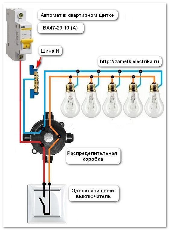
Attention!!! The switch should always break the phase, not the zero.
All this is necessary for our own sake. When replacing the lamp, it will be sufficient to disconnect the switch and there will be no voltage in the cartridge. Change yourself calmly. If you confuse, and switch the switch to zero, then when you replace the lamp, it will in any case remain energized. And this is very dangerous. Read my articles about and (example).
Looking for a malfunction
Let's return to the malfunction.
So, having unscrewed the bulb from the cartridge (E27) and turned on the switch, we check with the help of the coming phase (orange in the picture) from the switch to the lamp or not. In our case, the phase of the lamp does not come. This indicates the following faults. Either it is a faulty switch itself, or from the switch to the lamp is in the breakage (see circuit circuit breaker).

After removing the key, we will see the screws for securing the switch to the sub-socket and the screws for securing the wires to the switch. Here, we need to make sure that there is a phase on the conclusions.
For this we again apply, and we measure the incoming phase and the outgoing phase.
And here we were waiting for a "surprise".
The phase on the switch came, and from it did not leave any more. This indicates that the breaker itself is faulty. Therefore, it must be removed.
Turn off the voltage in the apartment with. By the way, this is the feature of this apartment. If you have in the apartment or are several lines (groups), respectively, turn off the machine of the line (group), where the work will be done.
Then unscrew the screws fastening the switch and gently bend it. Please note that I have not twisted the screws for fixing the wires yet.

Old enough.
The reason for the missing wire is the weak pulling of the screws for fixing the wires.
Completion of work
The fault has been eliminated, the wire is inserted back into the terminal and the screws are tightened.

The switch is connected. It remains only to insert it in and tighten the screws of the switch fastening.
And now you can check the work done. We turn on the voltage on the switched off part of the circuit and check the operation of the single-key switch. Everything works fine.

- one of the simplest. Step by step I explain how to assemble the connection scheme. Look at the photos themselves - in total there are three connections in the switchbox. Who did that knows - it's just that if there's nothing in the box besides these wires on the lamp and the switch. But often it happens that in the switchbox there are wires not for one lamp, and even on the outlets can be immediately laid out, then when assembling the circuit you need special care and accuracy. What would be clear even to the most inexperienced teapots, I wrote a photo-instruction.P.S. Well, on this and finish the article, where I told you about the scheme of connecting a one-button switch and how to troubleshoot a wiring.
Wiring diagram of the circuit breaker.
If there is no possibility to watch video, practically the same thing was written below. circuit breaker connection. Before starting work, we mean electric installation work, be sure to make sure that there is no dangerous voltage on the job site. Here I show how to assemble a circuit in a switch box, so there should be no voltage on the wires that are connected. We turn off the machine and check that the voltage is removed. Only after that we continue to work. When connection of a single-key switch In the switch box for the assembly of the circuit three wires must come: the first is the power wire, or the lead-in wire that goes to the machine or plugs with a voltage of 220 volts. The second wire is to the switch, the two-wire third is the wire to the lamp or lamp.Wiring diagram to the switch
By the way, many luminaires have a grounding clamp on the casing, so a three-wire wire-phase, zero and grounding is required. So, in the switch box comes three wires on two cores (the ground wire from the lamp does not count). Next, I'll call the veins wires - so right. After checking that the voltage on the wires there - remove the insulation in order to make twist. It is also suitable for this purpose and wago clamp, but I show on twist. The circuit is assembled as follows: circuit diagram of the circuit breaker. The switch is connected to the phase wire break. Zero wire goes to the lamp directly, naturally through a junction box. Phase through the switch is done to ensure that afterwards, when servicing the luminaire, repair or replacement of the lamp does not get under tension. And simply it is more convenient - turned off the light and change the lamp or lamp lightly.
  So we find the phase power wire that comes to the switch box from the input and connect it to one of the wires going to the switch. I always use a white or red wire for this. With the switch, the phase is returned by another wire and connected to the wire going to the lamp. The remaining wire from the lamp in the switch box is connected to the zero wire power supply. circuit breaker connection. I check the circuit as follows: visually I look in the switchbox - the phase came, went to the switch. With the switch came in the box - went to the lamp. With phase everything. Further. Zero came into the box - went directly to the lamp. All! The circuit is assembled and verified.
 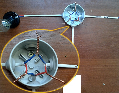 Next, I twist tightly twisting the pliers and weld with my new welding torch. Then I put on the PVC pipe and fix it on the twists with electrical tape. I put the wires neatly into the junction box and close the lid. All! That's how it is going to connection diagram of a light switch with one key. In the next lesson, I'll show you how to put together a circuit for connecting a two-button switch. More details on today's topic can be seen in the photos.
 The one-key switch is the simplest product designed to control lighting at home.
From time to time, such products have to be repaired or replaced, so it is desirable to provide a scheme for their inclusion and the principle of operation.
In this article you will find answers to your questions, diagrams and video recommendations on how to connect a one-button switch.
The switch is part of the circuit, which includes the source and the consumer of electricity. In this variant, this is 220 V network and lamp. To turn on and turn off such a luminaire between it and the network, there must be a disconnecting device.
A switch having one key is connected in series to the phase line of the network. In principle, it can be included in the zero line, but this, firstly, will contradict rules of the PUE, and, secondly, it will be unsafe for servicing electrical devices.
The danger is that when installing the device in the zero line, the energy consumer units will be energized even when it is in the off state. And when you touch the electric appliance, you may find yourself shocked.
To connect a lighting lamp to a network with the use is usually used in which switching is performed. In this case, to her suitable for 6 electric lines - two are supplied with voltage, two go to the lamp and two go to the switch.
How to choose the right one
Depending on the type of electrical wiring (or) in the house, switches of one or the other type can be used. They differ in their design in the part of installing them on the wall. In the first case, the device is installed on a wooden plate placed on the surface of the wall, in the second - into a metal or plastic padded wall embedded in the wall.
In any case, when choosing a switch, you should pay attention to its limiting characteristics. Usually the value of the operating voltage of the standard apparatus is 220 V, and the operating current is -10 A.
The passport also indicates the maximum switching power (standard -2.2 kW).
At the same time, the power of the consumer, for example, should not exceed this maximum power.
Installation and video instructions
When installing a light control system the greatest attention should be paid to:
- The correct connection of the elements in the distribution box.
- Correct connection of the switch itself.
Scheme for connecting a single-key switch to a light bulb:

To execute the first rule, you need to do the following:
- Identify, suitable from the network side. To do this, you can use a probe - with a neon light bulb. If you bring the probe to the phase, the neon light will begin to glow. If the probe is brought to zero, then there will be no glow.
- Turn off the power on the apartment.
- Connect the phase to one of the ones going to the switch.
- Connect the second cable from the switch, c, which fits to the center contact of the lamp socket.
- Connect the wire from the external contact of the socket to the mains lead.
The joining of the peeled ends can be carried out in various ways:
- twisting and subsequent soldering with further isolation of this place with tape or special caps;
- screw or bolt clamps;
- with the help of terminal blocks;
- spring clamps, for example of the Wago type.
The most reliable contact in this case provides the first option. Screw and bolted connections are reliable, but they can damage the connected elements. Spring clamps can be made very quickly, but eventually the springs are weakened, which leads to sparking and burning.
To execute the second rule, you must perform the following operations:
- Remove device key with a screwdriver with a thin sting. It should be borne in mind that modern plastic housings devices have a very fragile structure, so you should act cautiously.
- To reinforce the attachable version of the device with screws on a wooden spruce box. Connect the leads from the distribution unit to the terminals by screws.
- When hidden wiring at first make wire connections. Then install the housing in the niche of the wall and secure it with special paws by tightening the fastening screws.
- Set the key back.
Learn from this video how to properly connect a single-key light switch:
In the next video, we will tell you how to install the one-key switch correctly:
In conclusion, it is necessary to turn on the shield and check the system's operability and its adjustment.
Let's sum up. One-key switches are used to control the shutdown of power consuming means, for example lighting. Such apparatuses are connected to the phase conductor in series with the illumination means.
Installation of a system for disconnecting devices using electricity is performed using a special distribution box.
The device must be selected in such a way that its the limiting electrical characteristics were equal or more such characteristics of current consumers.