Antipyretics for children are prescribed by a pediatrician. But there are situations of emergency care for fever, when the child needs to give the medicine immediately. Then the parents take responsibility and apply antipyretic drugs. What is allowed to give to infants? How can you bring down the temperature in older children? Which medications are the safest?
The article describes several ways to detect hidden wiring in the wall of an apartment or other room, an overview of the useful devices for carrying out the relevant work.
The Benefit of Flush Mounting Wiring
Very often, starting a repair in an apartment or a house, there is a problem associated with the wiring.
In very old dwellings one can still meet the external arrangement of the wires, that is, they are simply fixed on the wall.
To trace in this case the location of the wiring is not difficult, because it can be seen.
But the practice of such a laying of wires has long been abandoned in favor of flush mounting, in which the cables are laid in special shtroby, after being closed.
It is conditioned by banal safety - an invisible wire can not be accidentally damaged, but only in case when nothing is done with the wall.

When can I find information about the location of the wiring?
During the repair, it is often necessary to drill the walls, and here the hidden wiring becomes a problem, especially if the cables have been laid down for a long time and there is simply no plan for the electrification of the room.
In order not to damage the wiring during the work, it is necessary to know its location.
In general, such information may be required in the case of:
- Re-planning of electrification of the room (changing the location of sockets, switches, etc.);
- Re-planning of the premises (making new openings - door, window);
- Occurrence of problems with wiring (breakage or short circuit);
- Improvements in the interior by hanging various appliances and furniture on the walls.
In the case of replacement, it is not necessary to know the location of the wiring, since the old one will still be removed, so the house network is de-energized, and then the wires are simply pulled out of the shrouds (they are usually plastered and pulled out easily), after which the circuit will be perfectly visible.

Information on the location of the wiring in the walls is most often required when drilling.
Let's address to the primary source
Many know that according to the PUE cables are laid only at right angles.
That is, the wiring is not located along the shortest path, it must pass only strictly horizontally or vertically, and the direction change is made at an angle of 90 degrees.
This information is not enough to determine where the cable is laid, but in the future it will help at least roughly understand in which direction to look for wires from the outlet or junction box.

Special devices and their operating principles
To identify hidden wiring, you can use special electrical appliances - searchers, which in the market of electrical goods is quite enough.
It is noteworthy that in such devices different principles of work are used, because of what they have their advantages and disadvantages.
So, you can purchase searchers:

Also produced are combined devices that use several operating principles at the same time, which increases the accuracy of the determination.
In addition, often such devices have additional functions that significantly expand their scope of application.
For example, the finder can additionally help in locating the wiring or grounding location, searching for a phase wire, etc.
Wiring seekers
Below are several types of instruments that the market is currently offering.
The first device is called "Search" and it looks like this.

This device uses the electrostatic principle of detecting hidden wiring.
It has 4 modes of sensitivity, it is able to detect the cable at a depth of up to 7 cm. Light and sound indication is used for the alert.
It has a number of additional functions, it is very easy to handle - choose the mode (to search the wiring is used the 4th) and drive the device along the wall.
Note that certain factors can affect its operation (the presence of metal objects, high humidity of the wall).
In general, "Search" is quite acceptable and inexpensive option for finding wiring, but it does not belong to professional devices.
A large number of analogues of such a device are produced - the same "Woodpecker", STR and a number of others.

The second device - MAG-2 looks like this.

It is combined and uses electrostatic and electromagnetic principles for detection.
It has two modes of operation - for detecting a powered network without load, and with a load.
Signaling - light and sound. Refers to amateur options.
The next representative of the searchers is Chinese, he does not have a title, but there is a denoting index - LA 1012.

This is a more "advanced" device, equipped with displays, which displays all the information.
It uses the electromagnetic principle of search, has a number of additional functions.
He already refers to professional devices and is not cheap.
Multifunctional professional combined instrument.

It is a metal detector that allows you to determine not only the depth of the cable, but also the material of its manufacture.
Equipped with an information display for displaying all information. Can also use electrostatic principle to search. A good enough and high-precision device is enough.
What else can help in finding hidden transactions?
Above, it was the searchers who could be purchased for personal use.
But often it happens that you only need to find the wiring and it's not advisable to spend it on a special device for this purpose, but you still have to find the wiring.
Indicator screwdrivers.
In this case, the indicator screwdriver can come to the rescue. Better, of course, to buy more modern, for example, this is a series of Chinese indicator screwdrivers MS, which has light and sound signaling.

But you can do with a conventional probe with LED indicator.

They work on electrostatic principle, that is, they are able to detect the electromagnetic field emitted by the live wiring.
In use, they are very simple - just put your finger on a special metal window (MS indicators) or touch the tip of a screwdriver (usual indicator), and then simply drive a screwdriver along the wall.
In the place where the wire is laid, such indicators will start signaling.

The disadvantages of this method of detection include a relatively small depth of detection (up to 2 cm), as well as a strong error, that is, it is impossible to accurately detect where the cable lies.
We can only determine the channel width of 10 to 20 cm. But this is often enough to perform the installation work associated with drilling the wall, you just have to do everything outside the boundaries of a certain channel.
The multimeter.
For search also can be adapted and.


To obtain the crawler, you must connect the specified elements correctly. This transistor has three outputs - drain, source, and gate.
To the first two terminals we connect the probes of the multimeter switched to the ohmmeter mode, the polarity being unimportant.
The shutter will play the role of an antenna (which can be slightly extended).
Having constructed such a device, you can start searching - the antenna is driven along the wall and we look at the meter reading - any deviations in the readings will indicate the location of the cable.
Smartphone.
Help with the definition of hidden wiring can help and a smartphone with a Mac or Android.
For them in the application store you can find the program "Metall Detector" or its analog.

Built-in smartphone magnetic sensor in combination with the specified software allows you to get a metal detector, which can detect a hidden cable in the wall.
But it is worth considering that it will react to all metal elements, so you can not apply it everywhere.
The accuracy of the search for a smartphone is sufficient to determine the channel in which the wiring is laid.
Alternative methods
Visual search.
If these devices are not available, then alternative methods can be used. And the first of them is visual.
In the process of sealing shrouds with cables, it is not always possible to do everything very smoothly.
Therefore, you can often find the location of the wiring on a small ledge, but for this you need to carefully consider the room, and the wallpaper will have to be removed - the wall should be "bare."

Radio.
Help in the search can and the usual radio, which does not need to be altered. It is enough to set the frequency at 100 kHz. And then we take the receiver and go in search.
For detection, we drive the antenna along the wall. The cable detection signal will be noise increase from the speaker.
Accuracy, of course, is not high, but it is quite possible to determine the channel with wiring.

You can also use an old tape recorder or cassette player, but for this you need to extend the wiring that goes to the magnetic head. That it will be an antenna.
That is, carefully remove the head from the player, extend the wires, and then drive it on the wall.

Popular from readers: the pros and cons of the device.
Homemade Seeker
Those who do not want to use improvised tools and have at least some experience in radio electronics can gather the searcher on their own, and this requires not so many components.
The simplest device consists of the same field effect transistor, ohmmeter (switch), speaker from a stationary telephone and a power source.
The device layout is as follows.

After connecting all the components of the circuit, everything can be "refined" - encased in a case, set to turn off or increase the number of indicators.
But we note that this device is the simplest, and therefore, its sensitivity is not high, although it will nevertheless make it possible to detect the channel in which the cable is laid.
In general, the schemes by which you can assemble a hidden wire finder are large, with varying design complexity and operating principles.
But we believe that the above methods are enough to detect hidden wiring in the apartment without finding incomprehensible for many details and soldering scheme.
THIS MAY BE INTERESTING:
It will be useful for anyone to know exactly how the hidden or the house passes. And there are several reasons for this.
To install various equipment during the repair, you will probably need to drill holes in the walls. And there is always a possibility that at such times the drill will fall on the metal elements, the parts under tension. The device for searching hidden electrical wiring will help to cope with the problem. This is necessary and, when the old wiring changes to a new one.
- We use in practice
- Conclusion
The main principles when searching for hidden transactions
Carrying out repairs, we do not always have at hand a special circuit with a picture of the places where the hidden wires are located. Often, even the basic requirements are not met, according to which any wires must strictly maintain their position in the vertical or horizontal plane. The detection of hidden wiring involves the use of two basic approaches.
- If the network is healthy, an alternating current will pass through it.
An electromagnetic field arises around any wire through which electricity flows. This is one of the basic laws in physics. It is this property electric current use for the work of most of the researchers who help with the definition of hidden elements.
- You can also use a so-called generator with an inductor. The electromagnetic field is distorted when wires or parts of the valve get onto such a concealed wire alarm. The indicator of the device will immediately show the corresponding data.
We use in practice
Price, functionality and design are the main differences between different searchers, which are produced in the modern market. E121 is a hidden wiring indicator that is very popular among electricians. The seeker has several advantages:
- Easily finds the internal network inside the plaster from any materials, at a depth of up to 7 cm.
- Relatively inexpensive device with no serious requirements for operation.
- At a cost of about 1500 thousand rubles.
The device for searching for hidden wiring MS - another series of devices, originally from China. Low price for many becomes an important virtue. Devices can react not only to wires, they are affected by other metal structures that are nearby. Unconditional minus for this device.
You need to have some experience to distinguish the signal of the wire from the signal of another metal part.
When installing concealed wiring, it is necessary to provide access to its elements in advance, in the case, for example, of a breakage. At least this applies to switchboards and lighting boards. A decorative and functional solution can be
Producers from foreign countries produce varieties of seekers with greater value. For example, the development of the company Amprobe - the device VP-440 - will help with the definition of the hidden routing of electrical wiring. It performs other actions, can find places with breaks. It costs about 35 dollars.
Internal power supply. How to find them quickly and easily
 There are alternative methods of detection. A radio tuner with a tuning for the average wave frequency of 100 kHz is one such available solution. It is enough to move the machine along the wall. So you can easily understand exactly where the hidden wiring is located. In the receiver there is a crackle and noise when it passes through the wiring.
To save on payments for electricity, our readers advise the "Energy Saving Electricity Saving Box". Monthly payments will be 30-50% less than they were before the use of the economist. It removes the reactive component from the network, as a result of which the load decreases and, as a consequence, the consumption current. Electric appliances consume less electricity, and lower the cost of paying for it.
You can use a modern smartphone to solve this problem. It is enough to install a special program and make sure that the device is supplied with a so-called magnetic sensor.
Can I make the equipment myself?
For this purpose, field-effect transistors are excellent, for example, from the KP103 series.
This element has its own characteristics. Its resistance changes when the gate is acted upon by an electromagnetic field. The battery and indicator light turn on in sequence.
An antenna that looks like a piece of wire can be connected to the gate of the transistor in order to increase the input signal. You need to drive on the wall of the antenna to find the hidden wires. By the maximum signal in special headphones it is easy to understand exactly where they are. The low-frequency amplifier can also be added, only the device will have more sensitivity.
The multivibrator and LED can become a more affordable alternative to the conventional amplifier in the circuit. The first one simply starts if hidden wiring is detected. And the light source just blinks.
On the features of work in some modern models
There is, for example, the MS-158 M searcher. It can react even to nails and reinforcement, other metal elements. Because professional electricians do not really like this device. It takes some time to get used to its peculiarities.
There is an earlier model of the MS-158 searcher. It received the designation MS-58M. The main difference is in the design of the case. It is more practical and modern, when it comes to the 158 series.
Testers of the type MS-48, MS-18 and so on are performed in the form of ordinary indicators. Require accuracy from the user with any level of preparation. With problems, even those who understand general principles work, but has no practical experience of handling them.
Indicators will glow constantly if they are exposed to high humidity levels, even in small ranges. But with proper skill, the accuracy will be maximum, the deviations will be plus or minus 15-20 centimeters.
There are better testers for a professional approach. To one end in these devices, connect a generator with a certain frequency. A receiver is used along the cable, which is tuned to the same frequency. If the key has changed - this is the place we need. But such devices are most actual in mobile electric laboratories, since they have a rather high cost. Unlike screwdrivers, for example.
About semiprofessional devices
In most of its with a universal purpose. Help determine the composition of the wall that is in front of them. The presence of black and non-ferrous metals. Testers generate their own electromagnetic field. It changes the readings and characteristics when it passes through different surfaces. It is enough to accurately analyze the data and determine what is in the wall.
Autocalibration of the sensing element makes the instruments with the microcontroller very accurate, in comparison with other classes. It is useful to find behind the wall not only the wires, but also the reinforcement, which is responsible for the amplification. Then you can not be afraid that during the repair the borax will fall on the pipes, break through the entire system. A simple screwdriver with such a study can not cope.
One of the simplest models is a BlackandDecker tester with a microcontroller. The display is built only on the LEDs. The device can be reconfigured as quickly as possible to search for wood or metal thanks to a hard mode switch. The device gives an audible signal if it is exactly "sure" of what is in front. An indication is displayed on a separate LED indicating that there is a wiring somewhere near the wall.
The error in detecting objects in such models is minimized. Scanning is done in only one direction. With the detection of wooden and metal frames, the ZirconTriScannerPROSL tester can help. The LED indicates approximately the direction in which the object of interest is located. Regardless of the selected scan mode, the presence of wiring is determined continuously.
Conclusion
It does not matter which device the buyer chooses. It is important to check its operability before starting operation. It is best to test the devices on a site where the location of the networks is already known. This will help to understand which position of the antenna is most convenient.
Sometimes testers react poorly to the network because of the batteries that have sat down. It is necessary to create conditions under which the device gives the most accurate readings.
If you are going to carry out installation works that can lead to damage to hidden wiring, then you need to find a place where there would be no wires under the plaster. And if you are not a professional electrician, you do not need to buy a special device once. You can make an indicator of hidden wiring with your own hands from what you find at home.
It is possible to think up many variants of execution of the detector of the latent conducting. Schemes of some devices are simple and understandable for the schoolboy, the schemes of others are available for experienced electrical engineers.
They differ among themselves by the number and types of elements: see what you have on your hands, and from this choose the scheme.
Important! Keep in mind that some homemade articles with incorrect assembly can give a signal for no reason or not at the right time at all: it is not safe to use such devices.
Scheme with sound indicator
This non-contact concealed wiring indicator is based on a chip K561LA7. To protect it from a high voltage created by static electricity, a 1 MΩ resistor is required (on the diagram R1). The device is powered from the crown (9V). As an antenna, a copper wire or any metal rod with a length of 5 to 15 cm is suitable. The golden mean is 10 cm. It is important that the wire does not bend under its own weight.
If you bring the assembled device to a live wire, you will hear a sound resembling a crack. This is possible due to the presence of piezo-emitter (in the scheme ЗП-3), which increases the volume. Search for this detector can not only covert wiring, but also a burned light bulb in a garland. You can find out about its location by the fact that near it the cracking stops.
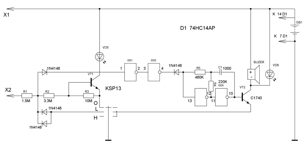
Scheme with sound and light indicator
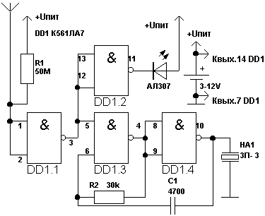
This device can be powered by batteries with a voltage of 3 to 12 V. To limit the current, a resistor R1, whose resistance should not fall below 50 megohms. But for the LED (marked AL307) such a resistor is not provided: it is not needed, because the used microcircuit ( K561LA7) will do everything herself.
As the searcher approaches the live wire, not only noise will be heard, but the LED will also light up. Dual indication is more reliable.
Two-element indicator
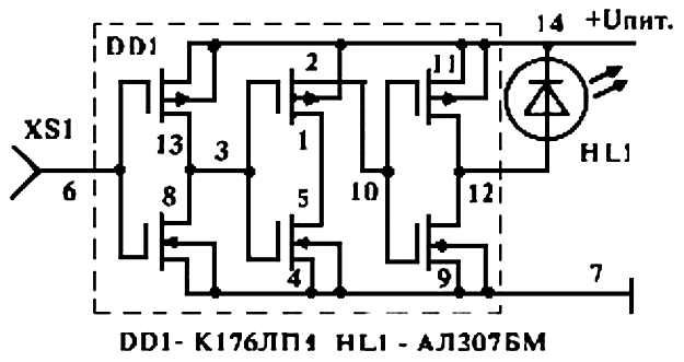
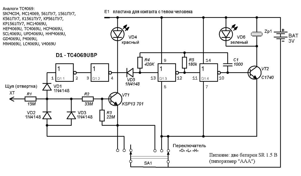
You only need a microcircuit and an LED. For assembly will suit DD1 and HL1 respectively. The whole purpose of the job is to connect the pins of the chip so that there are three inverters in the chain. Such a hidden conductor searcher with his own hands increases the currents that lead to the device field alternating current in wires hidden by a wall. As a result, when the wiring is approached, the LED light comes on, and when the chain is removed or broken, it goes out.
Execution options 2:
- Connect the leads: 3rd - with 8th and 13th, 2nd - with 10th, 4th - with 7th and 9th, 1st - with 5th, 11th - with the 14th;
- Connect the leads: 3rd - with 8th, 10th and 13th, 1st - with 5th and 12th, 2nd - with 11th and 14th, 4th - with the 7th and 9th.
Detector on microcontroller
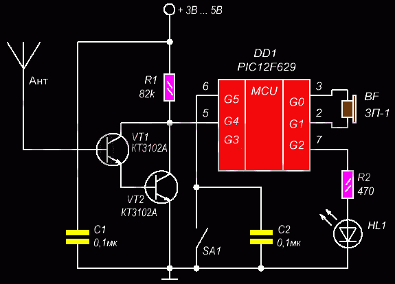
This diagram shows the hidden wire finder on the microcontroller PIC12F629. Its action is based on the sensitivity to the magnetic field, created by a current with a conductor hidden in the wall. Depending on which display method you prefer (light or sound), you can include a piezo-radiator or lED light bulb. Therefore, you will find out about the detection of the magnetic field of the hidden wiring from a tanned light bulb or a characteristic cod.
This device has an undeniable advantage: it reacts only to the frequency of 50 Hz - this is the frequency of the alternating current. An erroneous operation of the signal is excluded: the magnetic field from a source with a frequency of less or more than the specified will not activate the device.
Flush-mounted wiring detector without batteries
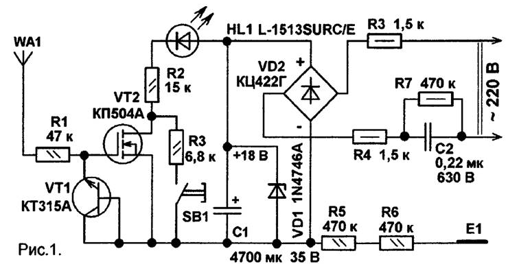 The hidden wiring detector with its own hands, the circuit of which is shown above, uses the network itself as a power source. This was made possible by the use of a capacitor with a large capacitance (in the scheme C1). You can charge it by connecting the device to the network. Charged capacitor produces a voltage of 6-10 V. And from its value depends only the brightness of the LED, the sensitivity of the device does not fall from this.
Industrial circuits of professional detectors and their analogs for home-made items
To make "Woodpecker" at home? Can. But it is complex in the assembly, which includes many elements. And from your care when reading the scheme and the accuracy of performance will depend on the quality of the analogue. Below are 2 schemes: the first industrial, the second - for a self-made "Woodpecker" (click on them to increase).
You can play and YADITE 8848, the variants of which are also shown on two electrical circuits (they also increase by clicking).
Testing of self-made hidden signaling devices
Before using the homemade products, it is necessary to conduct a test of hidden detectors. It will show whether the device works correctly. Testing procedure:
- Find a site in which 100% passes the hidden wiring (sockets and switches);
- Test the homemade alarm by running it along the wall around the outlet;
- If the signal arrives only at the point where the cable passes, you can use the device;
- If the signal then appears, then disappears in different directions from the socket, then the device does not work.
Attention! Before searching for hidden wiring, give it maximum load. To do this, turn on the maximum of electrical appliances. This will help to strengthen the electrical and magnetic field, to which testers react.
In order not to hit a puncher or nail in a walled cable, it is necessary to get acquainted with the wiring diagram in the apartment. But often it is lost, and the search for wires is difficult. However, with the help of a self-made detector of electrical wiring you will accurately determine the place where you can hang a shelf or picture. For this, you do not need to rush into the store: all the elements you will find at home in the old electronics.
Sometimes the desire to relax on nature outside the city is so great that people simply buy themselves vacation home. After purchase, as a rule, repairs are carried out, and non-toxic, and cardinal work, which affects even wiring, but it is often there are difficulties.
 In private homes, especially when it comes to old buildings, there are no plans for electrical wiring. As a rule, the entire system is installed in walls, and it is difficult to find it, but it is possible to detect hidden wiring with the help of a detector. This device is divided into many types. It can be purchased both in the construction market and made by hand, even if a person does not have certain skills in electrical engineering.
 During repairs in a private house, it may be necessary not only to redevelop the electrical system, but also there may simply be problems if you want, for example, to hammer a nail, and there passes wiring. In the end, at best will have to open the wall and restore the wiring, and maybe so that a person will get a serious injury from the discharge of electricity. Therefore, when working with electrical wiring you need to use a special device to detect the electrical system in the wall.
In addition, such a device can be used not only during repairs, but also simply if you want to install a decor, or rather, to nail a picture or install an additional outlet. The reasons for using the detector, as can be seen, can be many. Of course, you can do without a detector, but simply logically guess the location of the wiring, which can go either horizontally or vertically, but this method is rather risky. The hidden wire search detector allows you to pinpoint the location of all cables.
Nowadays there are a large number of models of detectors, designed to search for hidden wiring. If earlier it was possible to determine only their position, evaluate the plan of the electrical system or simply find metal objects in the wall, then modern models can determine even the gaps in the wiring. Sometimes this helps a lot, because when the wiring breaks, you do not have to open the entire wall in search of a defect, but simply break a hole in the place of breakage. Detectors can also be divided by type:
- search for the depth of the cables;
- material of cables;
- by time of work;
- number of additional functions.
 The simplest model is called an electrostatic device. It is cheaper than other models and, in addition, is easy to use. Another advantage of this model is that the device can detect wiring, capturing a large radius of the wall, and therefore do not have to check every centimeter of the surface. This detector also has several significant drawbacks. For example, it can not be used indoors if electricity is simply turned off. In addition, in places with high humidity, such as garages, baths, saunas, the appliance simply will not work. Also, the device can not detect wiring if the wall is made of metal material.
There is another budget option, a detector for detecting hidden wiring. This detector operates on the principle of an electromagnetic pulse, which allows you to find the position of the wiring with great accuracy. It can fix the location of even the wiring, which has a load of only 1 kW, that is, it is able to recognize the location of the cable even in the off state. Detector actually reacts to metal, which is part of the wiring, but this option is not always on hand when checking.
In private houses that are built of wood material, the detector will work well. In case the construction is made of panel elements, which include steel bars, the detector will react to any presence of metal.
The most popular for today is the combined detector for detecting hidden wiring. It allows you to locate the location of the electrical system with high accuracy. In addition, you can select the function to work with this device. Thus, it is possible to determine cable breaks, the presence of non-ferrous metals, wood or plastic material. Combined detectors have only one significant drawback - high cost.
 The variety of detectors for detecting hidden wiring is quite large in the modern construction market. Therefore, before you go for a purchase, you need to decide for what purposes it will be targeted. For example, it can be used only once or repeatedly. Detector may be needed to detect a simple circuit cable or to search for all hidden details in the room wall.
It is also worth taking into account its characteristics. This refers to the power, the depth of the wall scanning and the operating time. If you select the wrong type of device, you can simply skip some section of the cable, since the device simply is not designed for a sufficiently large depth of scanning.
Professional models of the device are used, as a rule, in enterprises where the depth of the cables can be quite large. Such a device, of course, will detect wiring at any depth, but because of its high cost, it simply does not need to work in domestic conditions. If it is a question of checking the presence of a wiring in a private house or apartment, a simple type that will accurately indicate the location electrical network. The simplest type of detector that works with the electricity on is usually not very effective, but suitable for one-time use and protect against injury and burns.
 As a rule, all concealed wiring detectors operate on the principle of detection electric field. Expensive models can detect such a field even when the electricity state is off. The detector catches an electric field and sends a signal, which will indicate the location of the cable.
Before starting work the device is switched on with the help of a special button, located on the body of the device. As a rule, immediately after switching on it starts calibration itself, for more accurate work in the future. At this time, you can not interfere with the calibration or bring the device to the wall, where there simply is no wiring, but you can help if you place the device in the place where the cable passes exactly.
After the calibration is over, you can start working. The device is carried over the entire surface of the wall. The signal of detection of the wiring will be received when the device detects the cable. Typically, the timing of such work depends on the quality of the detector model. As mentioned earlier, the detector can be used on large areas of the wall surface, while cheap models can fix the signal from the electric field only in the range of several centimeters.
In addition, the operation of the device also depends on whether they are under voltage or not. Cheap models may simply not work on wet surfaces or in places with a thick layer of finishing material or simply show inaccurate results.
 Of course, it's much easier to buy a device for detecting hidden wiring, but if it is used only on an amateur level, then it will be enough to have a device that can be done simply with one's own hands. is he it can only work at cable locations, which are under tension and the accuracy of the indicators will not be so high. But the device is suitable in case you just need to make a hole for the picture and make sure that there is no cable in the wall.
Schemes for creating your detector on the Internet are many, but they are all built on the same principle. It is necessary:
- pick up the material;
- assemble the device.
In order to assemble the simplest concealed detector, you will need to find an ohmmeter and a conventional field effect transistor. All these details can be bought in any construction market at a fair price. You can also use the headset in the device, which has a battery. In this case, the device will show the location of the wiring, not only with the deviation of the arrow, but also a characteristic signal will be heard. The phone is only needed for comfortable use of the device, and on all other parameters it has no effect.
The assembly of all necessary parts is fast enough. It is only necessary connect an ohmmeter to a field effect transistor and start checking the wall for wiring. As a rule, if the cable is there and the device catches an electromagnetic field, then the arrow simply deviates sideways in places where the power is the greatest.
In the case of telephone connection, the principle of operation does not change. Here the difference is that when searching for a cable, the device will issue a signal, which as you approach the electromagnetic field will simply increase.
The whole principle of the self-made detector for detecting wiring is based on the properties of the field-effect transistor.
Apparently, such a device is not particularly powerful and can only be used at a shallow depth of the wiring. In addition, it will work only if there is tension. As a rule, he suitable for work in domestic conditions, but if there is a check at the enterprise or a person is engaged in repair or construction work, it is best to purchase a multidetector. It can and costs more, but it greatly simplifies the operation and improves the accuracy of the cable search.
A wide variety of detectors is on the market. The most popular and universal are:

Due to the variety of detectors for detecting hidden wiring, you can greatly simplify the work in the construction sector, repair or simply when installing any element of the interior, when you need to break through the wall. The device also reduces the level of danger to human health when working with the power grid.
- Печать!}
There are ways to detect hidden wiring "folk" methods, without special instruments. For example, you can include a large load on the end of this wiring and search for a compass deviation or using a wire coil with a resistance of about 500 Ω with an open magnetic circuit connected to any amplifier's microphone input (music center, tape recorder, etc.), making the maximum volume. In the latter case, a wire in the wall will be detected by a 50 Hz pickup sound.
The device № 1. It can be used for detection of the latent electroconducting, search of breakage of a wire in a plait or a cable, revealing of the burnt out lamp in an electrogarlands. This is the simplest device, consisting of a field effect transistor, headset and batteries. The schematic diagram of the device is shown in Fig. 1. The scheme was developed by V. Ognev from Perm.
Fig. 1. Schematic diagram of a simple searcher
The principle of operation of the device is based on the property of the channel of the field-effect transistor to change its resistance under the influence of pickups on the output of the shutter. Transistor VT1 - KP103, CPSOZ with any letter index (at the latter the output of the case is connected to the output of the shutter). Phone BF1 - high resistance, resistance 1600-2200 Ohm. The polarity of the battery connection GB1 does not play a role.
When searching for hidden wiring, the transistor body is driven along the wall and at a maximum sound volume of 50 Hz (if it is wiring) or radio transmissions (radio network) determine the location of the wiring.
The place of wire breakage in an unshielded cable (for example, a power cord of an electrical or radio set), a burned-out electric lamp is looked for like this. All the wires, including the broken one, are grounded, the other end of the broken wire is connected through a 1-2 MΩ resistor with a phase conductor of the mains and starting from the resistor, move the transistor along the bundle (garland) until the sound disappears - this is the place of the wire break or a faulty lamp.
The indicator can be not only the head phone, but also an ohmmeter (shown as broken lines) or an avometer included in this mode of operation. The power supply GB1 and the phone BF1 are not needed in this case.
Device number 2. Now consider the device made on three transistors (see Figure 2). On two bipolar transistors (VT1, VT3) a multivibrator is assembled, and on the field (VT2) - an electronic key.

Fig. 2. Schematic diagram of a three-transistor finder
The principle of this searcher, developed by A. Borisov, is based on the fact that an electrical field is formed around the electric wire - it is picked up by the searcher. If the button of the SB1 switch is pressed but there is no electric field in the zone of the antenna probe WA1, or the finder is far from the network wires, the transistor VT2 is open, the multivibrator does not work, the HL1 LED is off.
It is enough to approximate the antenna probe connected to the gate circuit of the field effect transistor to a conductor with a current or simply to the mains wire, the transistor VT2 will close, the shunting of the base circuit of the transistor VT3 will stop and the multivibrator will start to work.
The LED will start flashing. Moving the antenna probe near the wall, it is easy to follow the passage of network wires in it.
Field-effect transistor can be any other of the series indicated in the diagram, and bipolar - any of the series KT312, KT315. All the resistors - MLT-0,125, oxide capacitors - K50-16 or other small-sized, LED - any of the AL307 series, the power source - the battery "Corundum" or accumulator battery voltage 6-9 V, pushbutton switch SB1 - KM-1 or the like.
The body of the finder can be a plastic case for storing school counting sticks. In its upper compartment, a board is attached, in the lower compartment, a battery is mounted.
You can adjust the vibration frequency of the multivibrator, and therefore the frequency of the LED flashes, the selection of resistors R3, R5, or capacitors CI, C2. To do this, temporarily disconnect the source of the FET from the resistors R3 and R4 and close the switch contacts.
The device № 3. The finder can be assembled and using a generator on bipolar transistors of different structures (Fig. 3). The field-effect transistor (VT2) still controls the operation of the generator when the antenna probe WA1 hits the electric field of the power wire. The antenna should be made of wire length 80-100 mm.

Fig. 3. Schematic diagram of the searcher with the generator on
Transistors of different structures
The device № 4. And this device for detection of damages of the latent electroconducting feeds from autonomous source voltage of 9 V. The schematic diagram of the finder is shown in Fig. 4.

Fig. 4. Schematic diagram of the finder on five transistors
The principle of operation is as follows: one of the wires of the concealed wiring is supplied with an alternating voltage of 12 V from the step-down transformer. The remaining wires are grounded. The finder is turned on and moves parallel to the wall surface at a distance of 5-40 mm. In the places where the wire breaks or ends, the LED goes out. The crawler can also be used to detect damage to cores in flexible portable and hose cables.
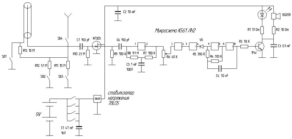
The device № 5. The detector of the latent conducting, presented on fig. 5, is already implemented on the K561LA7 chip. The scheme is presented by G. Zhidovkin.

Fig.5. Schematic diagram of the hidden wire finder on the K561LA7 chip
Note.
Resistor R1 is needed to protect it from increased voltage static electricity, but, as practice has shown, it can not be set.
Antenna is a piece of the usual copper wire any thickness. The main thing is that it does not sag under its own weight, i.e., it was rather rigid. The length of the antenna determines the sensitivity of the device. The most optimal value is 5-15 cm.
Such a device is very convenient to determine and the location of the burnt out lamp in the Christmas tree garland - beside it the crack stops. And when the antenna approaches the electrical wiring, the detector emits a characteristic crack.
Device No. 6. In Fig. 6 shows a more complex searcher, who has, besides sound, also a light indication. The resistance of the resistor R1 must be at least 50 MΩ.

Fig. 6. Schematic diagram of the finder with sound and light indication
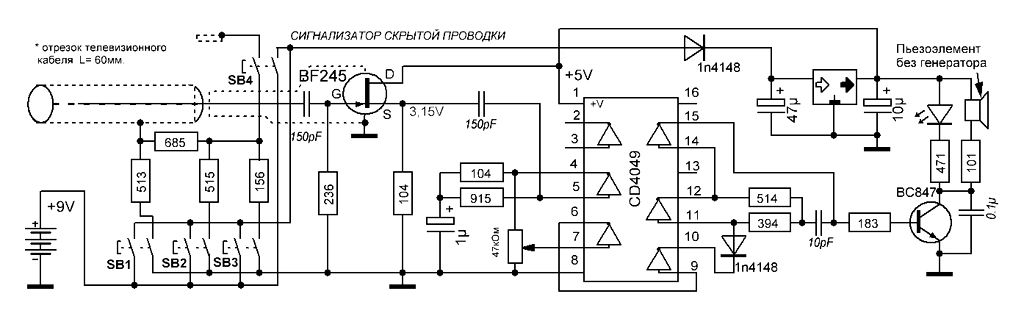
The device No. 7. The finder, whose circuit is shown in Fig. 7, consists of two nodes:
♦ AC voltage amplifier, the basis of which is the micro-power operational amplifier DA1;
♦ oscillation generator of audio frequency collected on the Schmitt DD1.1 inverting trigger K561T1 chip, frequency-assigning circuit R7C2 and piezo-radiator BF1.

Fig. 7. Schematic diagram of the searcher on the chip K561TL1
The principle of the seeker is as follows. When the antenna WA1 is located close to the current-carrying line of the power grid, a 50-Hz EMF pickup is amplified by the DA1 chip, which causes the HL1 LED to light. The same output voltage of the operational amplifier, pulsating at a frequency of 50 Hz, triggers an audio frequency generator.
The current consumed by the microcircuits of the device when powered by a voltage of 9 V does not exceed 2 mA, and when the LED HL1 is turned on it is 6-7 mA.
When the required wiring is located high, it is difficult to observe the illumination of the HL1 indicator and it is quite enough to sound an alarm. In this case, the LED can be turned off, which will increase the efficiency of the device. All the permanent resistors - MLT-0,125, tuned resistor R2 - type SPZ-E8B, capacitor CI-K50-6.
Note.
For smoother adjustment of the sensitivity, the resistance of the resistor R2 should be reduced to 22 kΩ, and its lower circuit connected to the common wire through a resistor of 200 kΩ resistance.
The WA1 antenna is a foil pad on a board measuring approximately 55x12 mm. The initial sensitivity of the instrument is set by trimmer R2. An unmistakably mounted device developed by S. Stakhov (Kazan) does not need adjustment.
The device number 8. This universal instrument-indicator combines two indicators, allowing not only to determine the hidden wiring, but also to detect any metal object located in the wall or floor (fittings, old wires, etc.). The schematic of the finder is shown in Fig. 8.

Fig. 8. Schematic diagram of the universal crawler
The concealed wiring indicator is assembled on the basis of a micro-powered operational amplifier DA2. When a wire connected to the amplifier input is located near the wiring, the 50 Hz frequency pickup is sensed by the WA2 antenna, amplified by the sensitive amplifier assembled on the DA2, and switched at this frequency by the HL2 LED.
The device consists of two independent devices:
♦ metal detector;
♦ Indicator of concealed wiring.
Let us consider the operation of the device according to the basic scheme. A high-frequency generator is assembled on the transistor VT1, which is input into the excitation mode by adjusting the voltage on the base of VT1 using the potentiometer R6. The RF voltage is rectified by the diode VD1 and converts the comparator, assembled on the DA DA1, to the position at which the LED HL1 and the periodic audio generator are off, the DA1 chip is off.
Rotation of the sensitivity knob R6 sets the operation mode of VT1 at the generation threshold, which is controlled by turning off the LED HL1 and the periodic signal generator. If a metal object enters the inductance field L1 / L2, the generation fails, the comparator switches to the position at which the HL1 LED lights up. A periodic voltage of about 1000 Hz with a period of about 0.2 s is applied to the piezoceramic radiator.
Resistor R2 is designed to set the threshold generation mode at the middle position of the potentiometer R6.
Council.
Receiving antennas WA 7 and WA2 should be as far as possible from the hand and be in the head part of the device. The part of the housing in which the antennas are located should not have an internal foil coating.
Device number 9. A small metal detector. A small metal detector can detect hidden in the walls nails, screws, metal fittings at a distance of several centimeters.
Operating principle. The metal detector uses a traditional detection method based on the operation of two generators, the frequency of one of which changes as the instrument approaches the metal object. A distinctive feature of the design is the absence of self-made winding parts. The coil of the electromagnetic relay is used as an inductor.
A schematic diagram of the device is shown in Fig. 9, a.

Fig. 9. A small metal detector: a - circuit diagram;
b - printed circuit board
The metal detector contains:
♦ LC-generator on the element DDL 1;
♦ RC-generator on elements DD2.1 and DD2.2;
♦ buffer cascade on DD 1.2;
♦ mixer on DDI.3;
♦ voltage comparator on DD1.4, DD2.3;
♦ Output stage on DD2.4.
The device works as follows. The frequency of the RC-generator should be set close to the frequency of the LC-generator. At the output of the mixer there will be signals not only with the frequencies of both generators, but also with a difference frequency.
The low-pass filter R3C3 selects the difference frequency signals that are input to the comparator input. At its output rectangular pulses of the same frequency are formed.
From the output of the element DD2.4 they come through the capacitor C5 to the connector XS1, into the socket of which the headphones plug is inserted with a resistance of about 100 ohms.
The capacitor and telephones form a differentiating chain, so the phones will hear clicks with the appearance of each front and the decay of the pulses, i.e. with twice the frequency of the signal. By changing the frequency of clicks, one can judge the appearance of metal objects near the device.
Element base. Instead of those indicated on the diagram it is permissible to use microcircuits: K561LA7; K564LA7; K564LE5.
The polar capacitor - series K52, K53, the rest - K10-17, KLS. Variable resistor R1 - SP4, SPO, permanent - MLT, C2-33. Connector - with the contacts closing when the phone plug is inserted into the jack.
The power source is the battery "Krona", "Korund", "Nika" or similar battery.
Preparing the coil. The L1 coil can be taken, for example, from an electromagnetic relay of a RES 9, a passport of PC4.524.200 or PC4.524.201 with an impedance of about 500 Ohm. For this relay, you need to disassemble and remove the movable elements with the contacts.
Note.
The magnetic relay system contains two coils wound on separate magnetic circuits and connected in series.
The common terminals of the coils need to be connected to the capacitor C1, and the magnetic circuit, like the case of a variable resistor, is connected to the common wire of the metal detector.
Printed circuit board. The parts of the device, except for the connector, should be placed on the printed circuit board (Fig. 9, 6) from the double-sided foil-coated fiberglass. One of its sides should be left metallized and connected to the common wire of the other side.
On the metallized side, you need to fix the battery and the "coil" "extracted" from the relay.
The outputs of the relay coil should be passed through the countersunk holes and connected to the corresponding printed conductors. The rest of the parts are placed on the print side.
Install the board in a plastic or rigid cardboard case on one of the walls of which fix the connector.
Adjustment of the metal detector. Set up the device should start with setting the frequency of the LC-generator within 60-90 kHz by selecting capacitor C1.
Then you need to move the engine of the variable resistor approximately to the middle position and select the capacitor C2 to produce an audio signal in the phones. When moving the slider of the resistor in one direction or another, the signal frequency should change.
Note.
To detect metal objects with a variable resistor, you first need to set the lowest possible frequency of the audio signal.
As you approach the object, the frequency will begin to change. Depending on the setting, above or below the zero beat (equal generator frequencies), or the type of metal, the frequency will change to a higher or lower side.
Device number 10. Indicator of metal objects.
When carrying out construction and repair work, information on the presence and location of various metal objects (nails, pipes, fittings) in the wall, floor, etc. will be useful. The device described in this section will help in this.
Detection parameters:
♦ Large metal objects - 10 cm;
♦ a pipe with a diameter of 15 mm - 8 cm;
♦ screw M5 x 25 - 4 cm;
♦ M5 nut - 3 cm;
♦ screw M2.5 x 10 -1.5 cm.
The principle of the metal detector is based on the property of metal objects to introduce damping into the frequency-setting LC-circuit of the autogenerator. The mode of the self-oscillator is established near the point of failure of generation, and the approach to its contour of metallic objects (primarily ferromagnetic ones) appreciably lowers the amplitude of oscillations or leads to the disruption of generation.
If to indicate the presence or absence of generation, then it is possible to determine the location of these objects.
Schematic diagram of the device is shown in Fig. 10, a. It has an audible and light indication of the detected object. A high-frequency self-oscillator with an inductive coupling is assembled on transistor VT1. The frequency-setting circuit L1C1 determines the generation frequency (about 100 kHz), and the L2 coupling coil provides the necessary conditions for self-excitation. Resistors R1 (GRUBO) and R2 (smeared) can be set the modes of operation of the generator.

Fig.10. Indicator of metal objects:
A is a schematic diagram; b - design of the inductor;
В - printed circuit board and placement of elements
On the transistor VT2 the source follower is assembled, on the diodes VD1, VD2 - the rectifier, on the transistors VT3, VT5 - the current amplifier, and on the transistor VT4 and the pseudo-emitter BF1 - the audible alarm.
In the absence of generation, the current flowing through the resistor R4 opens the transistors VT3 and VT5, so the HL1 LED will light, and the piezo-emitter will emit a tone signal at the resonant frequency of the piezo-radiator (2-3 kHz).
If the HF self-oscillator will work, then its signal from the source follower output is rectified, and the minus voltage from the rectifier output will close the transistors VT3, VT5. The LED will turn off, the alarm will stop.
When the contour approaches the metal object, the amplitude of the oscillations in it will decrease, or the generation will fail. In this case, the minus voltage at the output of the detector will decrease and a current will flow through the transistors VT3, VT5.
The LED will light up, an audible signal will sound, indicating that a metal object is near the contour.
Note.
With the audible alarm, the sensitivity of the device is higher, since it starts to operate at a current of a fraction of a milliampere, while a much higher current is required for the LED.
Element base and recommended replacements. Instead of the ones indicated in the diagram, the device can use the transistors of the CASE (VT1), HF, HPS, HVT2, KT315B, KT315D, KT312B, KT312V (VT3 - VT5) with a current transfer ratio of at least 50.
LED - any with a working current of up to 20 mA, diodes VD1, VD2 - any of the series KD503, KD522.
Capacitors - series KLS, K10-17, variable resistor - SP4, SPO, trim - SPZ-19, constant - MLT, C2-33, P1-4.
The device is powered by a battery with a total voltage of 9 V. The current consumed is 3-4 mA when the LED is off and increases to about 20 mA when it is lit.
If it is not used frequently, the SA1 switch may not be installed, supplying voltage to the device by connecting the battery.
Design of inductors. The design of the inductor coil of an auto-generator is shown in Fig. 10, b - it is similar to the magnetic antenna of the radio receiver. On a round rod 1 of ferrite with a diameter of 8-10 mm and a permeability of 400-600, paper sleeves 2 (2-3 layers of thick paper) are put on, they wind the coil to the winding with a PEV-20.31 coil L1 (60 turns) and L2 20 turns) - 3.
Note.
Winding at the same time must be carried out in one direction and connect the leads of the coils to the auto generator
In addition, the coil L2 must move along the rod with little friction. The winding on the paper sleeve can be fixed with an adhesive tape.
Printed circuit board. Most of the parts are placed on a printed circuit board (Fig. 10, c) from a double-sided foil-coated fiberglass. The second side is left metallized and used as a common wire.
The piezo-emitter is located on the back of the board, but it must be isolated from the plating with tape or tape.
The board and battery should be placed in plastic housing, and the coil should be installed as close as possible to the side wall.
Council.
To increase the sensitivity of the device, the board and battery should be placed a few centimeters from the coil.
The maximum sensitivity will be on the side of the rod on which the coil L1 is wound. Small metal objects are more convenient to detect from the end of the coil, this will allow more precise determination of their location.
♦ Step 1 - pick up the resistor R4 (for this, temporarily solder one of the terminals of the diode VD2 and set the resistor R4 of the maximum possible resistance so that there is a voltage of 0.8-1 V on the collector of the transistor VT5, and the LED should shine and the sound signal sound.
♦ step 2 - set the resistor R3 to the lower position in the circuit and solder the diode VD2, and solder the L2 solder, then the transistors VT3, VT5 must close (the LED goes off);
♦ Step 3 - gently moving the resistor R3 up in the scheme, to achieve the opening of transistors VT3, VT5 and the activation of the alarm;
♦ step 4 - set the sliders of the resistors Rl, R2 to the middle position and solder the coil L2.
Note.
When L2 approaches L1, generation should occur, and the signaling should be turned off.
♦ Step 5 - Remove coil L2 from L1 and achieve the moment of failure of generation, and with resistor R1 it is restored.
Council.
When tuning, it is necessary to strive for the coil L2 to be removed to the maximum distance, and resistor R2 could be prevented from breaking and regenerating the generation.
♦ Step 6 - Set the generator on the verge of failure and check the sensitivity of the device.
At this setting the metal detector is considered complete.