Antipyretics for children are prescribed by a pediatrician. But there are situations of emergency care for fever, when the child needs to give the medicine immediately. Then the parents take responsibility and apply antipyretic drugs. What is allowed to give to infants? How can you bring down the temperature in older children? Which medications are the safest?
Feedthrough switch, same as switch. Some call it a "changeover" switch. The algorithm of its operation is uniquely determined by the name. The switch provides the connection of one common contact with one or the other of the two alternatives. Rarely, but there are also three-key switches.
It should be noted that prices for loop-through switches recently are often even lower than for conventional switches of the same manufacturer (for example, this applies to Legrand).
Therefore many sellers stop buying switches, offering switches instead. In fact, there is nothing wrong with this. Just use two of the three switch contacts - common and one of the alternatives. Moreover, appearance such devices is similar.
Lighting control from two places
The use of switches allows you to organize the switching on and off of the load (usually, lighting) from several points. The first figure shows the principle of operation of such a scheme. The meaning of her work is that in a chain consisting of two switches (switches on alternate contacts), changing the position of any of the switches immediately causes a connection or disconnection of the common contacts.

Picture 1
For a conventional switch, the "on" and "off" status is determined by the position of the key. For a circuit of two switches, at any fixed position of the key of one switch, it is possible to switch on or off the connected load by changing the position of the key of the other switch.
The main problem with the installation of pass-through switches is a very accurate determination of the purpose of all contacts of the installed devices. Same circuit diagram The device can be implemented constructively in a completely different way.
All three contacts can be on one side of the mechanism, can be distributed in any combination to any points. Switches are produced by a wide variety of manufacturers (Legrand, ABB, Schneider Eltctric ...).

An example of the location of the pass-through switches in the figure (Figure 2)
If the concept of using switches for controlling light from two places looks very simple, then a real connection using junction boxes requires increased care.
As shown in the figure with the diagram, at least two two-wire and two three-wire wires are connected.

Wiring diagram for two switches from different locations (Figure 3)
When using two-key switches, the number of wires suitable for them is doubled.
Three-place lighting control
If you look closely at the next figure, you can see that you can control lighting from three places and, in general, from any number of places. To do this, we just need to put an additional device in the gap between our simplest switches.
This device is called a cross (or intermediate) switch. If you look closely at Figure 4, it becomes clear that this device consists of two pass-through switches between which a mechanical link is established.

Figure 4. Connection from three places and more
On the one hand, the two-wire line from the first in the circuit of the switch is connected to the common contacts of both switches that make up the intermediate switch. The output alternate contacts of these switches are combined as shown in the figure.

Figure 5. Example of arrangement of 3 switches
As a result, we have two operating states of an intermediate switch. Either the input two-wire line continues after this switch "as is", or after the switch lines change places ("crossed", hence the name). Thus, we have a device that performs a function similar to that performed by the first or last switch in the circuit.
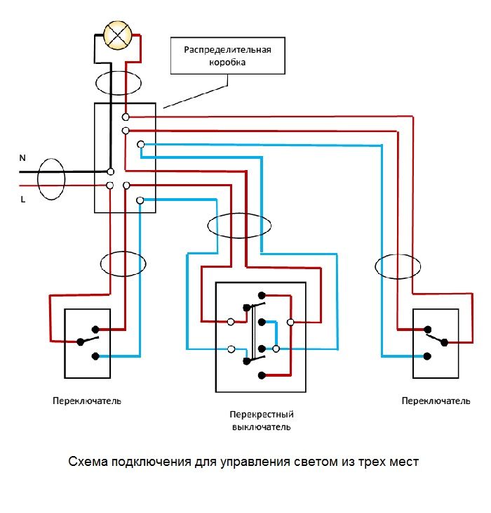
Figure 6
In the state shown in the figure, the circuit is closed. It can be opened by changing the state of any of the switching devices.
The installation of such a circuit (see connection diagrams in the figures) is complicated only in terms of the abundance of the wires being connected. When using one junction box, it must be connected in seven points (twists, terminal connectors) two two-wire, two three-core and one four-wire. For such a number of wires and connections, a sufficiently large junction box.
The situation can be somewhat simplified by using an additional junction box (as shown in the following figure).
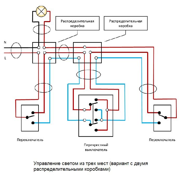
Figure 7. Connection of circuit breakers in 2 junction boxes
Two-key switches
All considered devices are produced in a two-key version. Connection scheme for two-key through-switch company Legrand is shown in Figure 8. It should be noted that the two-key switches are structurally designed as a combination of two switches installed in the mechanism counter to each other.
![]()
Figure 8
When mounting such devices, it is necessary to carefully understand the purpose of all contacts.
Generally speaking, the use of two-key switches is quite a rare phenomenon. In this case, the number of switched wires doubles compared to their number, which is necessary when using single-key devices. And we already noted that the number of wires and connections in such circuits is far from small.
A few words about the use of passing and intermediate switches. First of all, they are convenient in rooms and on sites, the size of which is large, and the entrance and exit are far from each other. It is convenient to use this technique to illuminate the paths in the garden, the hallway or the porch of the house, very often they are used to control the light on the stairs of a multi-storey building.
To control lighting from a large number of points, the use of pass-through and intermediate switches is a reliable method, but very costly in terms of spending wires and the laboriousness of switching work.

Figure 9
More suitable in this case is the use of bistable (that is, having two stable states) relays. To control such relays, impulse signals from switch-buttons (switches without fixing the position) are used. The signals from all such buttons are set to the bistable relay in parallel.
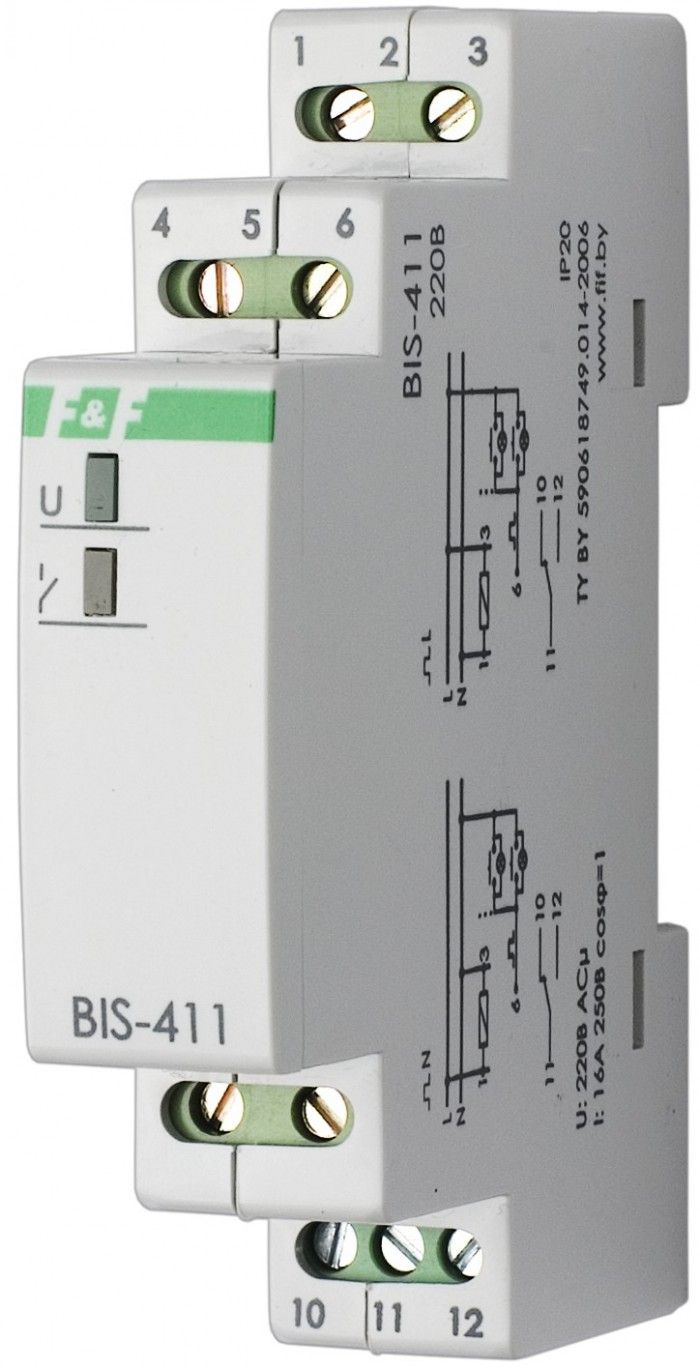
Figure 10. Bistable relay
It turns out a very flexible and easy-to-execute control scheme with an unlimited number of control points. The bistable relay itself is usually made in the form of a standard module, mounted on the DIN-rail in the box. The main drawback of this scheme is that you can purchase a bistable relay, as a rule, only in a specialized company.
Is it possible to turn on / off full lighting from any floor on the stairs? Easily! For this, pass-through switches are required.
You went into a long corridor, switched on the light; went through it until the exit, turned off the light ... How did this happen? Switching of the current is carried out with the help of the passage switches, therefore it is possible to control the same lamp from different places.
Circuit breaker connection scheme
The passing switch looks like a normal one. Moreover, it can operate as a conventional switch if two wires are connected to it: input and output.
The difference from a simple one is that the pass-through switch is, in essence, a switch. The input voltage is transmitted to one of the outputs; when turning it back on - one voltage is transmitted to one output from one of the two inputs.
Fig.1. Circuit breaker and loop-through switches
In order to perform switching of luminaires from different points, the circuit is assembled using devices:
- Pass-through switch
- Cross Switch
- Two-key through-switch
- Two-key shift key
Using a single pass switch, you can switch the light between two lights, or turn on / off one.
What pass-through switch, 3-point connection scheme?This is not one device, but a scheme of several - this is the subject of the conversation ahead.
First we will consider how to organize the control of a single bulb using two pass-through switches installed at different ends of a long corridor.
Scheme of connecting the pass-through switch with 2 places
Consider the circuit in Figure 2. With the switch positions shown, the light is on. If you click any switch, it turns off. But the most important thing is that if you then click any switch, the light will light up again. Highly simple circuit allows you to solve the problem: how to turn off the light on the second floor, including it on the first one; how to turn on the light, going into the bedroom, and turn it off, lying in bed.

Figure 2. The scheme of switching on and off of light from two points
The scheme of the inclusion of light from three points
In the previous section, we consider switching-on and off of electricity from two points: the circuit is very simple.
Well, if you need to turn on / off the light from three points? This problem arises when you try to save light in a multi-storey building and do not walk the stairs in the dark. Nothing complicated in this. But you need an additional switch, and not a loop, but a cross.

Fig. 3 Diagram of the cross switch
With the cross switch, you can transfer the phase from any input to any output, and you can disconnect the circuit between any pair of input-output.
Using a cross switch and two pass-through switches, it is possible to assemble a light-on-off circuit from those points, for example on a staircase in a three-story house:

Fig.4 Scheme of switching on and off of light from three points
Figure 4 shows the position of the switches at which the light is on. Clicking on any of those switches will turn off the light. After that, it is worthwhile to press the key on any switch - the light will light up.
And if the floors are not three, but five, six? You can assemble the circuit so that the light will turn on and off from any floor.
Pass-through switches always need only two: at the beginning and end of the chain. Between them put the cross switches. An example of a scheme for a four-story ladder is shown in Fig.
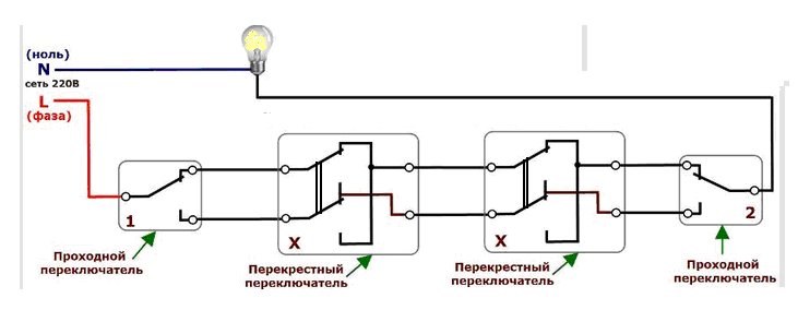
Fig. 5. Scheme of switching on and off of light from four points
Armed with a pencil and paper, you can draw different options and make sure that pressing any key on any switch leads to a change in the situation: the light turns on, and if the light is off, it lights up.
This remarkable scheme can grow if you add new cross switches to it.
No matter how many cross-switches with four contacts, there should be only two pass-through switches: at the beginning and at the end.
Scheme of connection of a two-key passage switch
The diagrams shown in the previous sections can be described as follows: one lamp and many switches, or rather pass-through and cross switches. These devices are similar to conventional switches and have one key.
But the sale is passkey two-key switches, wiring diagram which in Fig. 6,
as well as cross-key switches. These devices are used if you need to control two luminaires independently of each other.


Fig.6 Switches for switching on / off two lights
It is necessary to distinguish between the control of several bulbs that are synchronously ignited and go out, and those that can be switched on independently of each other. In the first case, apply pass-through switch, connection scheme for 1 key, in the second case we need two-key.
One-key through-switches can switch two, three, four light bulbs connected in parallel; constraint is superimposed permissible current, which can be switched by contacts.
Two-key switches are two independent switches in one housing. They can commute two independent groups of light bulbs. Connection diagrams of switches are two independent chains, each of which controls its luminaire or a group of fixtures.
Feedthrough switch for 2 keys
Switching of two luminaires, in which passage switch, Schneider, wiring diagram is shown in Fig. 7. 
Fig. 7. Diagram of switching on and off 2 light bulbs from 3 points.
Two-key switches require careful handling. If, when you press a single key, the light either lights up, or goes out (depending on the current state), in a two-key device each key is responsible for switching its group of fixtures.
Previously, the use of pass-through switches was advisable only because of the layout of the room or space when it was necessary to install a luminaire that can be adjusted from different locations. Now it also serves as a convenience and comfort, makes life easier. To control the lamp from several points, you need a wiring diagram for the switch from 3 places. Because it is the basis of controlled switches with 5, 6 or more seats.
- Installation diagram
- Example of lighting work
- Step-by-step installation instruction
Where is the system of three switches used?
Equipment switch with control from three different points provides practicality. The need to go through the whole room or a long corridor disappears to turn on or off the light.
Example of the location of pass-through switches in the bedroom
It is rational to use such a wiring system for the yard or infield. We left the house turned on the light, went to the building turned off. We went back on again, went to another facility.
For example, the room has several beds. The first device will be at the door, the second near one side, the third near the second side of the bed. That is, there is no need to get up to turn off the light.

Or lighting stairway opening, in order not to climb or descend in the dark. One switch is installed first at the bottom, next in the middle, and the third at the end, at the top of the stairs.
It is convenient to use a connection with 3 places in the entrances. On the first floor the lamp was turned on, on the second or third it was switched off. This significantly saves electricity.
It is actual to install switches on three points in elongated corridors and apertures, with several entrances to different rooms. At the beginning of the corridor turned on in the middle or at the end turned off.
The lamp control circuit is used both in one room and for a large space.
You can use such a lighting system even in the entrance rooms. In one room turned on, went through the room, in the other room turned off. Convenient and economical.
Installation diagram
To install a lighting fixture that can be switched on and off from three different locations, a three-pass switch is required.

The circuit consists of a junction box, a lamp, switches, wires. The source of illumination can be lighting - incandescent lamps, energy-saving, LED. Lighting installation involves the use of switches. They are of several types: through-pass and cross-over. The pass switch has also names - flip-flop, backup, ladder. Installation of such a switch is more difficult than installing a simple one.
To control lighting from 3 places, 2 pass-through switches and 1 cross-over switch are needed.
The appearance of the backup device resembles a single-key device. The switch in any position of the key does not stop the connection electrical circuit, and switches contacts. The switching mechanism in the through switch is in the middle of the contacts.
To save on payments for electricity, our readers advise the "Energy Saving Electricity Saving Box". Monthly payments will be 30-50% less than they were before the use of the economist. It removes the reactive component from the network, as a result of which the load decreases and, as a consequence, the consumption current. Electric appliances consume less electricity, and lower the cost of paying for it.
There are one key and two key pass-through switches. The two-key switch is two single keyboards in one and has six contacts.
The main advantage of the staircase switches is that the light can be adjusted from different points.
The diagram shows through-pass switches with one key. These devices are the same. They have three contacts. A phase is connected to them. At the first one, the contact is for the phase, and 2 contacts for the intermediate wires. At the third device on the contrary - 1 contact is connected with an intermediate wire, and 2 - for an output phase.
The design in the middle is called a cross switch. The toggle switches are connected by electric wires, and between them cross, which has four contacts. Two wires per switch for each switch.
When any one of the change-over switches closes the intermediate conductor, the light will light. The chain is closed and when the status of the key changes, the light goes out.
Important! Observe the safety measures. Check the power supply with a screwdriver indicator! Be careful when working with power tools.
Principle of the cross disconnector
The cross switch is similar to the usual one key, the difference is only in the presence of four terminals. The cross is named because of the two electrical lines that it switches, they are connected to a cross.
The cross disconnector simultaneously disconnects the first and the second switch, then synchronously connects them. From this movement of the contacts, the light lights up and goes out.
Advice! Pay special attention to the correct connection of the ends of the cables, otherwise the whole system will not work.
The number of points can be different, but the more of them, the more difficult the switching in the junction box. It is necessary to clearly label the wires when conducting so as not to confuse.
Example of lighting work

Necessary equipment and materials
- Switches
- Mounting box
- Electrical Insulation Tape
- Terminals
- Phillips screwdrivers and conventional screwdrivers
- Knife for installation
- Side cutters
- Pliers
- Spanner wrenches
- Electrical cable
If there is already a wiring in the room, and you need to install duplicate switches, then you need to either open the cables.
In order to make the stitrons need a puncher and shtoborez. Still need the alabaster. He will attach the goftrub.
In the case of open installation, a junction box is required, with the help of a goffrub, it is fixed to the wall.
Step-by-step installation instruction
The ends of all cables are led to a junction box and connected by terminals. A zero goes to the lamp.
For the equipment of the pass-through switch with control with 3 places it is necessary to have skills and an exact connection scheme. Its presence makes it possible to conduct a correct and high-quality lighting system. And on its basis, you can easily create more complex schemes of illuminations.
Switches and sockets are an important part of the electrical equipment of the room. After all, the better the contact when switching on the switch, between the outlet and the plug, the less it will heat up and, accordingly, the probability of a fire will decrease.
Below there is a list of popular electroaccessories
Legrand
ABB (ABB)
Polo (Polo)
Vico (Vi-ko)
Makel
Types of switches and their connection schemes
There are several types of switches and, accordingly, various types of connections:
,
,
,
Also, there are switches with illumination, however, when connecting this type of switches, it is desirable to pay attention to the type of light source, for example, fluorescent lamps in a circuit with a switch with a backlight, in the off state it will glow slightly.
One-button switch. Connection diagram
The simplest chain is y single-key switch and a power controller.

The one-key switch has only two contacts and something in it is confusing quite difficult. The circuit is switched as follows: We find the power wire: zero and phase, then neutral wire We serve immediately on the lamp (lamp, chandelier), and phase - on the switch. After that, from the switch we throw the wire to the light source. Typically, the circuit is switched through a junction box, where the wires are twisted properly.

The power regulator also has two contacts, with the only difference being that this regulator does not just turn on and off the light, but adjust it smoothly.
Please note that not all lamps work with this device. Therefore, before installing the power regulator it is advisable to check with the electrician or the seller.
Two-key switch. Connection diagram
Two-key switch works like two one-key keys.
The only difference between the chain of two one-button and one two-button is the absence of duplicate wires.

Those. it does not make sense to stretch out two "neutrals" to the lamps that are located side by side.
The two-button switch has three contacts. Figuratively speaking, one entrance and two exits. It is important to find a common (incoming) contact, otherwise connecting incorrectly, the lamps will turn on incorrectly. It is important to know where the input is, and changing the wires at the output will only change the keys that are responsible for the inclusion of one or another group of lamps.
Feedthrough switch. Connection diagram
It would be more correct to call it not a switch, but a switch. The essence of it is that it switches the supply of current from one wire to the other. As a rule, they are used in pairs. Pass-through switches, often used in long corridors, staircases, etc. See the diagram, I think it's clear on it.

The pass-through switch also has three contacts, as well as a two-key switch, but, as you can see, it works differently. In it, as in the two-key, there is one input contact and two outputs. It is important to know where the input is, and changing the wires at the output will only change the position of the key. If the breakers are not correctly connected, the circuit will not work properly.
Crossover switch. Connection diagram
This type of circuit breaker is used in the case that it is required to switch on / off one light source from three or more places, less often to switch the supply of polarity of the power supply. In the first case, it is used together with two passages. That is, the circuit of the switches must begin and end with a passing switch, and between them you can establish theoretically an infinite number of crossings.

Cross-switch has four contacts: two input, two output. The essence of switching is that in one position the first input wire is closed with the first wire at the output, the second input is closed with the second output wire, in the other position, the wires, as it were, change places. The first input is closed with the second output, the second input with the first output. Here it is important not to confuse and pay attention to the notation, and then the chain will not work correctly.
Setting the switch