Antipyretics for children are prescribed by a pediatrician. But there are situations of emergency care for fever, when the child needs to give the medicine immediately. Then the parents take responsibility and apply antipyretic drugs. What is allowed to give to infants? How can you bring down the temperature in older children? Which medications are the safest?
You come to your home, turn on the lighting in the corridor, take off your shoes, take off your outer clothing, turn off the light in the corridor, and in the darkness, trying not to touch anything, go into the room. It's good if you have a short and wide corridor, and there are no obstacles on the way. Agree that it would be much more convenient not to turn off the light, but to go to the end of the corridor and turn it off there, that is, to have lighting with two switches.
In the case of a corridor, a lamp with two switches is not that urgent. But how to be if you have to climb the stairs of your house to the second floor in the dark during the dark hours, then the installation of a chandelier for two switches would be much more useful. Although for many a second chandelier switch near the bed - the thing is very comfortable. He went to bed, as usual, read or squeezed the tablet, and without getting up turned off the light before morning. It is not so difficult to do this. No tricky device is needed. The lighting scheme with two switches will require only a section of a three-wire cable and two three-position switches.
It is a so-called pass-through switch (switch), it is a two-diapason or a two-pole switch. In the schemes it is depicted in different ways, but the essence of this does not change. Any of the two switches in the circuit can, regardless of the position of the other switch, both turn off and turn on the required load. Below are a few options that will help understand how it works.

Scheme of connecting the luminaire to two switches

Luminaire distribution to two switches

One-key through-hole switch with indicator
As already mentioned, the pass-through switch is very convenient in long spaces, when it is required to control the lighting from two places. It can be connecting the chandelier to two switches in the room, especially in new-fashioned studio apartments, and use in corridors, on stairs, and even to illuminate the walkway from the gate to the house in the suburban area.
There are situations when it is convenient to be able to turn on and off the light from two places, for example at the beginning and at the end of the passage along a long corridor or staircase.
Lighting with two-way control
The only difference between the installation of a luminaire with two-way control from the usual is the circuit for connecting switches (switches). Set the luminaire and both switches in two directions, then lay the cable with 1.5 mm2 conductors from the power source to the luminaire and from it to the nearest switch. Do not connect new wiring to the lighting circuit until the work is completed. Route between the switches a cable with conductors of 1.5 mm2.
2. Fixture
3. Lighting circuit cable
4. Switch Cable
5. The switch in two directions
6. Connecting cable
7. The junction box
To the terminal L of the first switch (left in the diagram), connect the phase conductor from the source (junction box or flap), and to terminals 1 and 2 - two wires connecting it to another switch.
In the second switch, connect the two leads from the first switch to terminals 1 and 2, and connect the L terminal to the phase terminal of the luminaire. Also connect the green-yellow conductor to the ground terminal of the luminaire (if not, isolate its end), and the blue conductor to the neutral terminal.
Make sure that the voltage is disconnected, and connect all new wiring to the shield or to the network in the junction box. Check the new wiring.

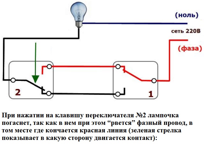
The lamp circuit is open. Pressing any switch key will turn on the lamp

The right switch key is pressed, the circuit is closed, the luminaire is on The red dashed line shows the flow of electric current. Pressing any switch key will turn off the lamp.
Illumination with three-way control
By adding an intermediate switch to the circuit described above, you can control the luminaire from three locations. This switch is placed in the rupture of the connecting wires between the two other switches.
In one position of the intermediate switch button, terminal L1 closes with terminal 3, terminal L2 - with terminal 4, in another key position: L1 - with terminal 4, and L2 - with terminal 3. Phase terminals L1 and L2 connect to terminals 1 and 2 of the first switch in two directions, and the output terminals - with terminals 1 and 2 of the second switch in two directions.
If necessary, you can increase the number of control points by adding intermediate switches to the circuit.

2. Fixture
3. Lighting circuit cable
4. Switch Cable
5. The switch
6. Intermediate switch
7. Connecting cable
8. The junction box
Alt = "(! LANG:\u003e Three-place lighting control scheme">!}
Three-place lighting control scheme
1. The power supply circuit of the luminaire is open. Pressing any switch key will turn on the lamp
2. The middle (intermediate) switch key is pressed, the circuit is closed, the lamp is on. The red dashed line shows the flow of electric current. Pressing any switch key will turn off the lamp
Control lighting by pulse relay
Switching the lighting on and off from several places is possible not only with switches, but also with impulse relays. This is most justifiable for controlling lighting from more than two places. Pulse relays will simplify the installation of the lighting control system and reduce the cable consumption.
Pulse relays and buttons
Pulse relays allow you to control the lighting system using buttons with normally open (normally open) contacts. Buttons look like ordinary switches, but their key is spring-loaded: in the initial position, the contacts are open and close only for the time when the key is pressed (see page 149). Relays are available for a rated current of 16 A.
Comparison of lighting control schemes from several locations
The drawback of the traditional lighting control scheme from several places with the use of switches in two directions and intermediate (cross) switches is a large expense of expensive cables, complicated installation.
Pulse relays make lighting control from several locations more efficient. Significantly reduces the cost of cable and simplifies installation. The length of the control line can reach 600 m, and the number of control buttons is unlimited. The use of illuminated buttons is allowed.

1. The junction box
2. The switch in two directions
3. Intermediate switch

1. The junction box
2. Pulse relay

A1 and A2 - terminals of the coil of control coil 1 and 2 - terminals of power contacts
In electrical engineering, electromagnetic relays serve mainly for remote switching on or off of consumers. In general, the electromagnetic relay is an electromagnet that closes or opens the power contacts when a comparatively low-power signal is applied to its winding. In fact, the relay is a switch or switch, which we can remotely control, up to several hundred meters away, sending a control signal to it via wires (feeding its winding).

When the control signal is applied to the winding contacts, the electromagnet overcomes the force of the return spring and turns the armature around the axis. The movable contact closes the load circuit. When the control signal is disconnected from the winding, the armature will take its initial position under the action of the spring, and the power contacts will open, de-energizing the load. Very often the relay is supplied with one more fixed power contact - normally closed (normally closed). This contact is closed (pressed against the movable contact) in the absence of a control signal and opens when it is applied. Such a relay can act as a switch. The location of the relay outputs (contacts) and its circuitry are usually shown on its housing.

1. Winding leads
2. Winding of the electromagnet (relay coil)
3. The core of the electromagnet
4. Yarmo (magnetic core)
6. Return spring
7. Mobile power contact
8. Fixed power contact
9. Stationary normally closed power contact
A pulse relay is similar in principle to an ordinary electromagnetic relay, but a short-time (pulse) control signal is used to activate it. When the pulse is applied, the armature is attracted to the core and remains in this position due to a special mechanical latch, that is, the contacts remain closed after the control signal disappears. When the control pulse is repeatedly applied, the latch releases the armature and, under the action of the return spring, opens the contacts.

A1 and A2 - coil terminals of the control coil
1 and 2 - power contact terminals
Wiring systems, in particular, the organization of lighting, provides elements for controlling electrical appliances. This function belongs to switches or switches, as they are called in everyday life.
In the past few years, a walk-through switch has been installed to control lighting in the home or indoors in general, to save space and convenience. It has a number of identical names - duplicating, flip-flop or cross switch or switch. Herself wiring diagram pass-through switch almost do not differ from the installation of conventional switches.
It works on the same principles as the usual single switch, but it has extended functionality. So, the installation through-switch It is relevant in cases where it is necessary to install several lighting devices, united in a single electrical circuit, for example, to install in the room the main (ceiling lighting element) and an additional light source - a lamp on the wall. Pass-through switches are installed to illuminate two rooms simultaneously, for example a toilet and a bathroom. For massive lighting structures, for example, multi-tier chandeliers or spot lighting of a single room, in particular a network fluorescent lamps It is also advisable to install a pass-through switch, the installation scheme of which is not very complicated.
The circuit for connecting a 2-way pass-through switch, which we will consider, will allow youinstall two circuit breakers near the entrances to the room. In the absence of experience, better order household services at home . But you can do it yourself. You just need to follow the installation, connection, and do not forget about safety. So, how make a light switch from two places?
Installation of a pass-through switch: stages of work
- Determined circuit-breaker circuit with two seats. It's pretty simple. In the junction box is fed 2 wires - zero and phase. Zero is immediately connected to the contact of the lighting device. The phase is carried out to the first breaker and connect up to a common contact of the two interrupters. From this contact we conduct a bridge between the switches. On the second, this vein is connected to a common contact. To the second, zero is applied from the lamp. The two remaining contacts are connected through a box with a phase wire.
- Prepare the installation site and conduct the wires. Here there are two tasks - we must properly dilute the veins and determine the places of installation of the circuit breakers and wire box according to circuit diagram of a two-button toggle switch. Having determined, we do wiring and a special bit, drill large holes for installation of the box and circuit breakers. Wires are better to use three-core and different colors. And connect each other strictly by color, to prevent short circuits.
- We make installation of a through switch and junction box. To do this, special plastic cups are inserted into the finished holes. They lead to veins and are connected to the equipment. Then it is inserted into place. With the help of fixing screws and retractable assemblies we fix them in boxes. Close the connection box with screws or snaps. The installation is completed.
For your own safety it is better to entrust this work electrician , but if you have the initial knowledge, then you can try to connect the pass-through switch yourself. The circuit diagram of the pass-through switch is presented in detail
Cross-switch installation options
At the moment, there are several options for how to make a pass-through switch or the types of connection of the pass-through switches.
Here are the most popular and successful options:
1. Scheme of connecting the pass-through switch with 2 places - according to the scheme of this option, the control of lighting from two places is carried out. For its assembly, two single pass-through switches are used. Each of them has one point of contact at the entrance point and two similar points at the exit. Connecting the pass-through switch from two places, assumes:
- Wire "zero" comes from the power source through the switch box to the lighting device.
- "Phase" is also connected through the box to the common contact of the first switch.
- Output contacts from it, again, through the box connect to the analogous contacts of the second switch.
- As the final step from the 2nd device from the general contact, the wire through the box is connected to the lighting device and the connection of the pass-through switch is completed;
2. The next option involves the management of two places at once groups of lighting devices, you will need a circuit for connecting the pass-through switch to 2 keys. As an example, there is a room with an adjoining corridor. Also there is a chandelier for five lamps. Our task is to install pass-through switches to control two groups of bulbs on one chandelier. We use 2 double pass-through switches, it turns out that we will have 2 entry points and 4 outputs. Otherwise, the order of connection is similar to how to make a light switch from two places.
Circuit-breaker circuit diagram
 When you press a button on one switch, the light turns on. This is due to the closure of the common wire and the supply of zero from the light bulb. Then, after going through a long room or down from the floor, going out, pressing on the button of another switch, the network opens. The light goes out. Now on one the contact bar is located at the bottom, and on the other at the top. Regardless of which side you turn on the light, closing the contacts will allow you to do this. The system is very simple and reliable.
In the same way, you can connect three switches. Add one installation location, additional wires. The layout remains the same. The main thing is to connect the wiring correctly, do not rush.
The main question - we were dismantled. But there are still a few nuances:
1. Safety rules during work. They are few and they are very simple.
Do not work when the electric current is switched on. Be sure to make sure before work so that no one could turn on electricity. Hang the warning sign.
When mounting, make sure that the wires and contacts of the switches are correctly connected.
2. When buying equipment and wires, pay special attention to the quality of products, ask for certificates and do not pursue cheap goods.
Having fulfilled all the requirements, you will get a bright and comfortable accommodation. The described method is suitable for people who have encountered a replacement wiring, otherwise, you'd better turn to specialist.
Light and joy to your home!
The issues of lighting management or other consumers electric power From different places for owners of apartments and private houses are quite relevant.
In rural areas, the home master can realize in such a way the economical use of outdoor fixtures when moving from a residential building to a zone of outbuildings when he needs to perform certain work, for example inside a garage or workshop.
Remote control of the light can be done in a city apartment.
Principle of light source control from two places
The adjective "pass-through", added to the noun "switch", or more precisely - the switch, indicates the conditions of its operation, when "passing" by this device, it is possible to turn on or off the lighting lamps.
Pass-through switches can be located at a considerable distance from the controlled light source and placed in separate rooms.
Consider an example of an apartment in which an ordinary electric switch for lighting a room can create certain inconveniences. We are used to being usually located at the entrance to the room near the door.
If the passage into the room is through the corridor, then the latter requires turning on the light.
We remove in the corridor the outer clothing for the street and go into the bedroom. Here, too, you need to turn on your lamp. Now we do not need the corridor lighting and it needs to be extinguished. It is necessary to return to the corridor and operate with an input switch. It's pretty inconvenient.

It is possible to think a little and adding gate switches 1 and 2 to it. The conditions for controlling the light in the corridor will be simplified, it will not be necessary to walk around in the half-darkness of the apartment.
Having installed two passage switches inside the corridor and the bedroom, more conveniences are created. Both switching devices No. 1 and No. 2 allow to operate equally with light from any of the rooms.
How does the connection circuit for the on / off switch operate when controlling the light from two locations
For the basis of the lighting system, created by this principle, the conventional and switch are used. from its tire in the housing without any breaks directly connected with all the metal cases of electrical appliances. We do not show it to simplify the information provided on the diagram.
The working zero, highlighted in blue, is fed through junction box to the proximal contact of the electric cartridge, inside which the incandescent bulb is screwed.

All light inclusions are carried out only through the use of a phase conductor. It can be tensioned. Both pass-through switches are connected in phase of the power supply system in series, counter-clockwise.
It should be taken into account design features pass switch and correctly connect incoming and outgoing trunks, highlighted in the figure in different colors.
Features of connecting the circuit wires to the contacts of the feedthrough switch
From the above diagram it can be seen that the pass-through switch has one common terminal, through which voltage is supplied from the housing flap or it is directed directly to the light source. There are also two outgoing contacts. Each of them is connected to the circuit by manipulating the key on the front panel.

When it is transferred to the upper or lower position, the corresponding contact is connected to the voltage, as shown in the photo.
Usually on the body the pass-through switch has the factory marking of its terminals showing the circuit for connecting the wires to them. She can be trusted.
However, when installing the created lighting system, follow the electrical methods and check the reliability of making contacts when switching the key. This will avoid possible subsequent errors.
When choosing the design of a pass-through switch for a light source, pay attention to the compatibility of the permissible load, which can normally switch contacts and the total electrical power of the lighting devices. If the contacts do not allow such a job, then you will have to connect a magnetic starter of the corresponding nominal value.
Here we have considered the most typical and simple pass-through model. Trade provides them with a wide variety.
Types of pass-through switches
On the internal device and the number of control keys, pass models for domestic purposes are produced:
- single-key;
- two-button;
- three-key.
In addition to the keys for control can be used:
- sensor device;
- the remote control;
- other technologies.
The choice of the way to control the keys or another method does not affect the quality of the circuit, but provides various types of amenities that depend on the personal inclinations of the apartment owner and his budget.
Animated circuit, explaining the principle of the passage switch
With a properly assembled circuit, the light source will be reliably controlled from each switch. To do this, it is enough to change the position of any key.

As you can see, to set a strict position for each key for a clear indication of its orientation when the light is turned on or off, as for ordinary room devices with "off" and "on" indicators it does not work.
Both pass-through switches are interconnected during operation.
How does the connection circuit for the on / off switch operate when controlling the light from three locations
In the previous case, two internal backbones were created between the switch positions. When it is required to increase the number of places for control, then they additionally connect switching devices.
For three-seat lighting control, an additional structure is created from the paired switch-disconnectors.
![]()
In the rest the circuit of connection of the pass-through switch does not differ from the previous one. It also finds application in home wiring inside an apartment or a private house.
It should be noted that it is technically not difficult to implement control from more places. This is what happens inside production facilities of a large area and length.
But, to be engaged in such method in a home household network is not absolutely effective. can become much more complicated. With the urgent need for remote light control, it is easier to use another method, for example, a radio channel and a remote control.
This method is described with reference to. It can work well with other light sources.
While repairing or reconstructing the lighting system, do not forget about ensuring its electrical safety in or paved. It is impossible to suppose a fire and create the preconditions for getting electric traumas by tenants.