Antipyretics for children are prescribed by a pediatrician. But there are situations of emergency care for fever, when the child needs to give the medicine immediately. Then the parents take responsibility and apply antipyretic drugs. What is allowed to give to infants? How can you bring down the temperature in older children? Which medications are the safest?
The main purpose of CIP cables is the transmission of electricity over air lines. The cable is actively used in the removal of electricity from the main highways to residential and business facilities, while building lighting networks on the streets of settlements.
Self-supporting insulated wire (SIP)
Construction of self-supporting insulated wire
Phase aluminum wires Covered with light stabilizing insulation coating in black. The polyethylene coating has a high resistance to moisture and ultraviolet rays of the sun, which destroy the rubber or conventional polymer insulation.
The wires are twisted into a bundle around the zero aluminum core, in the center of which is a steel wire. The core of the zero core is the supporting base of the entire cable. Some designs of SIP cables with a small cross-section and a small number of cores have a light weight, since in these types there is no steel core. The CIP stands for self-supporting insulated wire.
Types and structure
There are five main types of SIP wires:
- SIP-1 includes three phases, each of which is twisted into a bundle of several aluminum wires around the core of an aluminum alloy. The wires of the fourth zero core are twisted around the steel core. The phases are insulated with thermoplastic, resistant to ultraviolet rays. On the cable mark SIP-1A, the neutral wire, as well as the phase conductors, is insulated. Such cables can withstand a long heating time at 70 ° C.
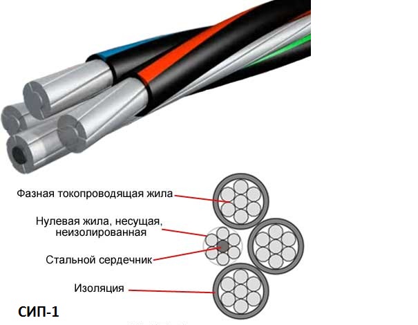
Cable construction СИП-1, СИП-1А
- SIP-2 and SIP-2A have a similar SIP-1 and 1A design, the difference is only in the insulating jacket. The insulation is "cross-linked polyethylene" - a compound of polyethylene at the molecular level into a grid with wide cells with three-dimensional cross-links. This insulation structure is much stronger to mechanical stresses and withstands lower and higher temperatures with prolonged exposure (up to 90 ° C). This makes it possible to use this brand of SIP cable in cold climatic conditions at high loads. The maximum voltage of transmitted electricity is up to 1 kW.

- SIP-3 - single-core cable with a steel core around which the wires are made of aluminum alloy AlMgSi. The insulated jacket made of "cross-linked polyethylene" makes it possible to use SIP-3 for the construction of overhead power transmission lines with voltage up to 20 kV. The working temperature of the cable is 70 ° С, it can be used for a long time at temperatures in the range from minus 20 ° С to + 90 ° С. Such characteristics allow the use of SIP-3 in various climatic conditions: in moderate climates, cold or in the tropics.

Internal installation of cable SIP-3
- SIP-4 and SIP-4H do not have zero wire with a steel rod, they consist of pairs of veins. The letter H indicates that the wires in the vein are made of aluminum alloy. PVC insulation is resistant to ultraviolet radiation.

Design of self-supporting insulated wire SIP-4
- SIP-5 and SIP-5N - the two wires have a similar structure with SIP-4 and SIP-4H, the difference is in the insulation shell. The technology of cross-linked polyethylene allows to increase the operating time at the maximum permissible temperature by 30 percent. Power lines using SIP-5 are used in cold and temperate climates, transmitting electricity with a voltage of up to 2.5 kV.

Internal device of self-supporting insulated wire SIP-5
Depending on the operating conditions and the load of electricity consumed, the brand and cross-section of the SIP cable are chosen.
SIP cross-section selection
The choice and calculation of the cross-section of the SIP wires for connection of various objects of consumption is carried out according to the classical method. The maximum power consumption of electrical installations is being built, calculation of the current load is carried out according to the formula:
I = P \\ U√³, where
- P - total power consumption;
- I - maximum current consumption;
- U - voltage in the network.
Guided by the value of the maximum current, the pre-calculated tables should select the required cross-section of the SIP wires.
Parameters of the most used CIP cables for connecting buildings from main transmission lines (SIP-1, SIP-1A, SIP-2, SIP-2A)
| Section in mm and number of cores | Sopro- tivle- phases in Om at 1km | Maximum allowable phase current c thermoplastic- teak iso- The | Maximum allowable current phase with cross-linked polyethylene- linen | Short current closures in kA with the duration 1c |
|---|---|---|---|---|
| 1х16 + 1х25 | 1.91 | 75 | 105 | 1 |
| 2x16 | 1.91 | 75 | 105 | 1 |
| 2x25 | 1.2 | 100 | 135 | 1.6 |
| 3х16 | 1.91 | 70 | 100 | 1 |
| 3x25 | 1.2 | 95 | 130 | 1.6 |
| 3х16 + 1х25 | 1.91 | 70 | 100 | 1 |
| 3х25 + 1х35 | 1.2 | 95 | 130 | 1.6 |
| 3х120 + 1х95 | 0.25 | 250 | 340 | 5.9 |
| 3х95 + 1х95 | 0.32 | 220 | 300 | 5.2 |
| 3х95 + 1х70 | 0.32 | 220 | 300 | 5.2 |
| 3х50 + 1х95 | 0.44 | 180 | 240 | 4.5 |
| 3х70 + 1х70 | 0.44 | 180 | 240 | 4.5 |
| 3х50 + 1х70 | 0.64 | 140 | 195 | 3.2 |
| 3х50 + 1х50 | 0.64 | 140 | 195 | 3.2 |
| 3x35 + 1x50 | 0.87 | 115 | 160 | 2.3 |
| 3х25 + 1х35 | 1.2 | 95 | 130 | 1.6 |
| 3х16 + 1х25 | 1.91 | 70 | 100 | 1 |
| 4х16 + 1х25 | 1.91 | 70 | 100 | 1 |
| 4x25 + 1x35 | 1.2 | 95 | 130 | 1.2 |
When choosing the section and the type of SIP wires it is important to take into account not only the maximum current load, but also the temperature, the time during which the cable can be operated under extreme conditions. Usually the permissible duration is from 4000 to 5000 hours.
Maximum temperature for wires
When choosing the type of cable and its cross-section for heating, it is necessary to take into account the type of insulation: cross-linked polyethylene or thermoplastic. Taking into account voltage losses, thermal stability in case of short circuit, mechanical strength, if one of the parameters is insufficient, a cable with a large cross-section is selected.
When using CIP, overload cables are allowed up to 8 hours per day, 100 hours per year and not more than 1000 hours for the whole period of operation. Most often, SIP-2A is used to connect residential buildings or utility facilities, this is due to some shortcomings of other cable models:
- on SIP-1 and SIP-2, the zero vein is not isolated, if it breaks, it can be induced, dangerous for human potential;
- SIP-1 (A), SIP-4 has a weak insulation;
- SIP-3 is used only at voltages above 1000V, this is a single wire;
- SIP-4 or SIP-5 do not have a central core, so they can only be used for short distances, at longer intervals the cable stretches and sags.
From the table above, it can be seen that the SIP-2A cable can be of the same or different cross-sectional conductors. Usually with a cross-section of phase conductors of 70 kV / mm, a zero core for strength is made 95 mm / sq. With a larger cross-section of phases, the supporting phase is not increased, mechanical strength is quite sufficient. With a uniform distribution of electricity in phases, the zero vein of electrical and thermal load practically does not test. For lighting networks, cables with a cross-section of 16 or 25 kV / mm are usually used.
Calculation example
An example of calculating the cross-section of a SIP cable for connecting an object with a total power of electrical appliances is 72 W, at a distance from the main power line of 340 m. Supports for suspending the SIP cable should be placed at intervals of not more than 50 m, this will significantly reduce the mechanical load on the wires. It is necessary to calculate maximum current for a three-phase circuit when all electrical appliances are switched on. Provided that the load will be distributed evenly between phases, one phase will be:
72 kW / 3 = 24 kW.
The maximum current in one phase, taking into account the inductive and capacitive load of electrical appliances (coefficient cos fi = 0.95) will be:
24 kW / (230V * 0.95) = 110A.
According to the table, a cable with a cross section of 25 A is chosen, but considering the cable length of 340 m, it is necessary to take into account voltage losses, which should not exceed 5%. For convenience of counting, the cable length is rounded to 350 m:
- in SIP the specific resistance of aluminum is 0.0000000287 ohm / m;
- the resistance of the wire will be Rpr. = (0.0000000287 / 0.000025) Ohm / m * 350 m = 0.4 Ohm;
- load resistance for 24 kW. Rn = U 2 * cos fi: P = 230 2 * 0.95 / 24kW = 2.094 Ohm;
- impedance - R full. = 0.40 Ohm. + 2.094 Ohm. = 2.5 ohms.
Based on the calculated data, the maximum current in the phase conductor will be:
I = U / R = 230V: 2.5 Om = 92 A
The voltage drop is equal to I max * Rpr. = 93A * 0.4 Ohm = 37V.
37 Volt is 16 percent of the mains voltage U = 230V, it is more than the permissible 5%. According to calculations, a SIP with a cross-section of 95 sq / mm is suitable. Losses with such a wire of 11 V, this is 4.7%. When calculating a single-phase line, the total power is not divisible by 3, the cable length is multiplied by 2.
Installation. Video
Tips for installing CIP wires to the house are presented in this video.
It can be concluded that the SIP cables have a number of advantages in relation to the old models aluminum cable, which has no isolation. The cable is reliably protected from short circuits when laying in tree branches and other difficult operating conditions. It can be laid on the walls of buildings, structures, along fences, and high qualification of workers is not required. The absence of special supports and insulators reduces the time and costs of installation. Thanks to insulation and other design features, the scope of application of SIP cables has expanded significantly.
Looking through the simplicity of the Internet on the subject of wiring, I found on one forum topic with the discussion "will the sip 4x16 15kW stand." The question arises because to connect a private house is allocated 15 kW 380 volts. Well, people are wondering whether it's not too little to lay 16 squares on a branch from an overhead line? I glanced at the PUAN, but for some reason I could not find anything on the subject of SIP power. Here there is only a label 1.3.29 "The permissible continuous current for not insulated wires according to GOST 839-80. "And it shows that the maximum permissible current for a section of 16kV mm wires AS, ASKS, ASK outside the room is 111 amperes. Well, at least something to start with.
How many kilowatts will it withstand 4х16?
But there is GOST 31943-2012 "Wires self-supporting isolated and protected for overhead power lines". At the end of the guest, in paragraph 10 of the operating instructions, there is a sign

How many kilowatts can a CIP withstand: table:
| Cross section SIP | voltage 380V | voltage 220V |
|---|---|---|
| SIP 4х16 | 38 kW | 66 kW |
| CIP 4x25 | 50 kW | 85 kW |
| SIP 4x35 | 60 kW | 105 kW |
| CIP 4x50 | 74 kW | 128 kW |
| CIP 4x70 | 91 kW | 158 kW |
| CIP 4х95 | 114 kW | 198 kW |
| SIP 4x120 | 129 kW | 225 kW |
| SIP 4х150 | 144 kW | 250 kW |
| CIP 4х185 | 166 kW | 288 kW |
| SIP 4х240 | 195 kW | 340 kW |
Method of calculation
Take the plate 10 and on it we find that one vein sipa 16 sq. M. withstands - 100 amperes. And then the most important thing is, how much should these 100A be multiplied by 220 or 380? Here it is necessary to look from the point of view of consumers who will be connected to the sipu. If this is an ordinary residential house, then there are not so many three-phase devices (well, the only thing is an induction cooker or an electric oven comes to mind, although they are inherently 220V), if it's some repair masterskaya, then three-phase equipment is already larger (lifts, compressor).
At the beginning of the topic was raised the question "will sip 4x16 15kW"? Therefore, for a private house we multiply 220Vh100A = 22kW in phase. But do not forget that we have three phases. And this is already 66 kilowatts in total for a house. What is 4x reserve concerning issued technical conditions.
Today, for the laying of electric power lines instead of a few separated bare aluminum wires, screwed to insulators, use a wire CIP(Self-supporting Insulated wire ). SIP is one or a bundle of several insulated wires, which is fixed to the supports with special fasteners for one or all the wires at the same time (depending on its type).
Species SIP
SIP has several varieties:
- SIP-1 - carrying zero vein without insulation, phase conductors are insulated. Insulation - thermoplastic light stabilized polyethylene. Fixes for a zero core. Operating voltage: up to 0.66 / 1 kV with a frequency of 50 Hz.
- SIP-1A - the same as SIP-1, but all veins are insulated
- SIP-2 - carrying zero vein without insulation, phase conductors are insulated. Isolation - cross-linked light-stabilized polyethylene (polyethylene with cross-linked molecular bonds). Fixes for a zero core. Operating voltage: up to 0.66 / 1 kV with a frequency of 50 Hz.
- SIP-2A is the same as SIP-2, but all veins are insulated.
- SIP-3 - solid conductor. The core is made of a sealed alloy or a densified steel-aluminum structure of wires. Isolation - cross-linked light-stabilized polyethylene. Operating voltage: up to 35 kV.
- SIP-4 - all veins are insulated. Insulation - thermoplastic light stabilized polyethylene. Does not have a supporting vein. It is attached to all the wires simultaneously. Operating voltage: up to 0.66 / 1 kV with a frequency of 50 Hz.
- SIP-5 is the same as SIP-4, but insulation is a cross-linked light-stabilized polyethylene.
For installation of overhead lines in SNT, the most suitable wire is SIP-2A.
Disadvantages of other types of SIP:
- At СИП-1 and СИП-2 on not isolated the zero vein at its breakage presence of dangerous potential for people is possible.
- SIP-1, SIP-1A and SIP-4 have less strong insulation.
- SIP-3 is designed for voltages above 1000 volts. In addition, it is a single wire, it is not folded into a bundle.
- SIP-4 and SIP-5 can only be used for taps to houses. Due to the absence of a reinforced carrier, the cores can stretch over time.
Calculation of the cross section of the phase conductors SIP
When calculating the cross-section of phase wires, one should take into account not only the maximum current that they can hold, but also the voltage drop at the end of the line, which should not exceed 5% when maximum load. At distances greater than 100 meters, the voltage drop in the line already becomes a bottleneck. The wire still holds the load, but too low voltage reaches the end of the wire.
Consider the situation on the example of my SNT. The length of the main line is 340 meters. The maximum power of power receivers is 72 kW. It is required to select the appropriate SIP. To do this, calculate the maximum current that can flow in the wires:
We calculate maximum power, falling on 1 phase.
72 kW / 3 phase = 24 kW = 24000 watts.
Let us calculate the maximum current of one phase. At the output from the transformer according to the standard 230 V. When calculating, we also take into account the capacitive and inductive loads from household appliances, using the cosine φ = 0.95.
24000 W / (230 V * 0.95) = 110 A
So, the wire should hold 110 A. We look specifications CIP for different sections, and we see that 110 A will withstand the CIP with a section of phase conductors of 25 sq. M.
It would seem, what else is needed? But it's not so simple. We have a line length of 340 meters, and any wire has its own resistance, which reduces the voltage at its end. According to the tolerances, the voltage drop at the maximum load at the end of the line should not exceed 5%. We will calculate the voltage drop for our case with veins of 25 sq. M.
We calculate the resistance of a 350 m wire with a section of 25 mm2:
The specific resistance of aluminum in the SIP is 0.0000000287 ohm-m.
The cross-section of the wire is 0.000025 sq.m.
The specific resistance of the wire is 25 sq. Mm = 0.0000000287 / 0.000025 = 0.001148 ohm-m
Resistance of 350 meters of wire cross-section 25 sq.m. = 0.001148 * 350 = 0.4018 ohm
We calculate the load resistance of 24 000 W:
We derive a formula that is convenient for calculation.
- P = U * I * 0.95
- from here
- P = U * (U / R) * 0.95
- P = U * U * 0.95 / R
- R = U * U * 0.95 / P
230 V * 230 V * 0.95 / 24000 W = 2.094 ohm
We calculate the impedance of the entire circuit, adding the two resistances obtained above:
0.4018 ohms + 2.094 ohm = 2.4958 ohm
We calculate the maximum current in the wire that can occur, starting from the impedance of the circuit:
230 V / 2.4958 ohm = 92.1564 A
Calculate the voltage drop in the wire, multiplying the maximum possible current and wire resistance:
92.1564 A * 0.4018 ohm = 37 V
The voltage drop in the wire of 37 volts is 16% of the initial voltage of 230 volts, which is much more than the permissible 5%. Instead of 230 volts at the end of the line at full load, it will be only 230 - 37 = 193 volts instead of 230 - 5% = 218.5. Therefore, the cross-section of veins should be increased.
For the case under consideration, the cross-section of phase conductors of 95 sq. M. This is much larger than the current required, but with the maximum load at the end of the line, this cross section will give a voltage drop of 10.8 V, which corresponds to 4.7% of the initial voltage, which fits in the tolerance.
Thus, for us for a line of 350 meters and a load of 24 kW per phase, a SIP-2A cross-section of 95 square meter phase conductors is necessary.
I note that with an uneven load on the phases, the current increases along the zero conductor, and hence its resistance also starts to play a role, and it should be included in the calculation (for example, to increase the calculated length of the wire, say, one and a half times). If the load is very uneven (for example, in winter, when 1-2 people live in a cold room, heated by electric heaters that sit on 1, or even in 2 phases), phase distortion may appear on the transformer itself. In this case, the voltage on the loaded phases drops even more, and on the unloaded phase it increases. Therefore, in an ideal such consumers should put a three-phase input, and include different heaters in different phases.
P.S .:
The single-phase line is calculated in the same way as the three-phase line, only the power of the consumers is not divided into 3 phases and the double line length is indicated, since in a single-phase line the zero vein is loaded equally with the phase conductor.