Antipyretics for children are prescribed by a pediatrician. But there are situations of emergency care for fever, when the child needs to give the medicine immediately. Then the parents take responsibility and apply antipyretic drugs. What is allowed to give to infants? How can you bring down the temperature in older children? Which medications are the safest?
Once they asked me to make a lamp that could change colors, for a monochrome one can quickly get a haircut: in short, something like a night light. Of course, the method of highlighting, which is described in this article, is also suitable for internal lighting of a computer, therefore this article can be interesting both from the point of view of design thought and for modding fans.
To make a normal tricolor lamp on toggle switches and three light-emitting diodes somehow did not feel like it, because it's much more interesting when the number of colors is not limited by the number of LEDs.
Necessary materials:
- A three-color super-bright RGB-LED with a diameter of 8 mm with a brightness of 4000 kd / d (or 3 super-bright LEDs with a diameter of 3-5 mm: blue, green, red).
- Variable resistors 0 - 1.5 kΩ with load shutdown - 3 pcs.
- Four-conductor wire
- Cube plexiglass 30x30x30 mm
- Housing for radio devices
- 3 knobs for adjustment
- Cover from plastic bottles (or a magnet from a PC-speaker)
- Adjustable power source (if this device you will be powered by a computer, take either a USB cable or a power splitter (molex))
- Heat-shrink, or insulating sleeves
- Black insulating tape
Instruments:
- Engraver (aka Dremel) - in principle, you can do without it
- Glue gun
- Set of files
- Drill
- Nadfili
- Sandpaper
- Pliers
- Side cutters
- Pistol knife
- Lighter
- A little imagination
So, let's get started.
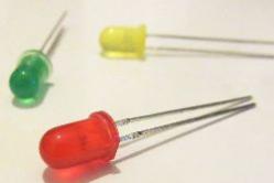
First, consider the tricolor LED. It has 4 outputs: common (+) and 3 legs responsible for color. By connecting a minus to one of the legs, the LED will glow either blue, or green, or red. It looks like this:

If you look closely, you can see that one of the legs inside the body of the LED is T-shaped - this is the general (+). In the photo, the legs are from left to right: red (-), common (+), blue (-), green (-). If you did not find a three-color LED for sale, then you can replace it with three monochrome ones, soldering their plus legs together.
In fact, the desired color of the luminaire can be achieved by changing the brightness of each of the three LED colors that will shine simultaneously from under the same plafond and, merging into one color, will give one that we need.
Adjustment of brightness will be performed by variable resistors, each of which will be connected in series with the legs of the LED color.
The variable resistor has 3 outputs:

The central leg is the general conclusion. Rotating the knob clockwise, the resistance between the first leg and the second (the central leg) will increase, and between the second and the third - decrease. It is most convenient to use the second and third legs - so rotating the knob clockwise, the brightness of the color will increase, to the leg of which this resistor will be brought.
Since the color management unit I decided to make remote, I had to buy a case for radio devices. The size of it should be such that it was enough to place 3 variables of the resistor. For example, the diameter of the round part of my resistors was 15 mm, respectively, a small-sized case was chosen. Low-power resistors have small dimensions, just such will be enough. The body is a plastic box with a lid, which is attached to self-tapping screws:

First, you need to select the location of the handles and determine which side the wire will go into the color control block, and which side to exit. Then we make the marking of the centers of the holes (it is very convenient to make it with an awl). Before you drill, you need to nail up the markup. You can do this with a 3 mm diameter drill, having scrolled it a couple of times by hand. Now drill the holes under the wire drill at low speed. If you drill on large ones, the plastic will float and it will have to be removed. The size of the hole will naturally depend on the diameter of the wires.
Before you drill the holes under the adjusting knobs, you determine the way of mounting the variable resistors. One way is to mount on a PCB and then secure it to the inner walls of the case. In this case, the handles are deepened into the body, respectively, the holes are made for them. The pens I used look like this:

If you do a hinged installation, you can simply drill holes in the case under the mounting of variable resistors, which I actually did. To me, for example, it is simply more convenient if the handle is fully open. When all the holes are drilled, we remove the burrs of the nads.
Regarding the power source - here you can take, for example, an adjustable power supply from 1.5 to 12 V with a step of 1.5 V.

The voltage must be set corresponding to the LED. Usually such LEDs are 3 V, so there's no need to put an extra resistor. Personally, I as a power source chose charging from Motorola C350 and put on each minus foot diode on a 150 ohm resistor.
If you connect our device to your computer, it can be powered either from a power strip (molex) or from a USB cable.
![]()

For those who do not know - the red wire in the Molex is +5 V, black is the ground. Either take the USB cable and cut off the unnecessary plug, leaving only the output to the USB. Strip it. There will be 4 wires: black (ground), red (+5 V), green and white (be sure to insulate them: they will not be useful to us). Since the power is 5 V, and the LED is 3 V, we set the resistor for each leg of the color of the LED. In this case it's 150 ohms (it's better to take a little with a margin).
Each LED has its own glow color. It depends on the semiconductor material and does not change during the operation of the device. To make multi-color LEDs, you need to collect together several crystals that emit different colors.
How does the two-color LED work?
The name of the two-color LED did not come from the fact that the device is somehow painted in a special way, but because it can glow with two colors. They are included separately. For example, if we are talking about a red-green lamp, at first only red is lit, then the red goes out and the green lights up. This feature is associated with the device device.
All two-color LEDs are made with two leads. The color changes depending on which way the current flows through the lamp. The circuit of such a device is quite understandable. It has a resistor and two diode connected to each other. The diodes are connected in parallel. When the current flows in forward direction, then one diode turns out to be locked and does not shine. With the reverse direction of the current, everything repeats the exact opposite.
A set of pure colors for LEDs is limited. With great effort, scientists have succeeded in creating crystals that generate colors similar to rainbow colors. There is:
- red;
- orange (amber);
- yellow;
- green;
- blue
And how many shades. White, like millions of other tones, is obtained as a result of their combination.
Principle of operation of a three-color LED
For the three-color LEDs, a slightly different circuit is provided. It has a common cathode and two anode terminals. It can include just two LEDs. In this case, both red and green light will simultaneously be lit, and we will see their result of teamwork - yellow.

With the help of a pulse modulator (a special device), the intensity of the glow changes, and the color tone of the LED changes from this. To prevent overloads, a resistor is installed on each diode.
The tricolor scheme is more in demand than the two-color scheme, and this is understandable. With the same set of sources, there are many more opportunities. This scheme allows you to collect inexpensive lamps that change light in a wide range.
Even more tones, including white light, are obtained by assembling a circuit with three different colored LEDs. This is a well-known RGB -circuit with a common anode. Externally, the tricolor lamp is immediately recognizable by the presence of four terminals, and the corresponding marking is necessarily placed on it.
Theoretically, it is possible to combine a lot of crystals in one case or on one board and get multicolored bright LEDs. But in practice one of the three-color schemes listed above is used.
Application
Despite its not very wide spectrum of radiation, two-color LEDs find their own niche in instrument-making. They are used for light signaling, in decorating rooms, in advertising. Two-color LEDs are indicators of the rotation of an engine running from direct current. They show the direction in which the rotation occurs.
Three-color LEDs working on two crystals find similar applications. Their advantage over the three-crystal lamps is a relatively low cost. At the same time, the capabilities of the devices are quite wide.
The work of this LED is well illustrated by the indicator light charger our cameras, phones, tablets and many other devices. When the battery is low, it glows red, and when fully charged, it turns green.
The very name - a two-color LED is based on the fact that the chip is able to glow with two colors. A vivid example of this type of diodes is charging a mobile phone, charging batteries, where the indicator lights up red while charging, the color changes to green when the battery charge is full.
Two-color LEDs are divided into several types. The most common are three-lead LEDs. In one case two LEDs of green and red light are integrated.
 Two-color LED with two leads
 Two-color LEDs have two outputs. The color change occurs depending on the direction in which the current flows. The two-color LED control circuit is shown below.
 Correct connection of a two-color LED
 The diodes are connected in parallel. When the current flows in one direction, the second diode is locked and does not shine. In the case of reverse current flow, the glow occurs in reverse. When using the PWM controller, both LEDs can be lit simultaneously, resulting in a yellow or a few other shades.
Despite the fact that in this scheme we see only two diodes, in some instructions it is usually called tricolor. Such diodes have three conclusions. This division is conditional, so it is not necessary to focus on this.
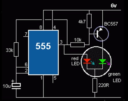
Control circuit for two-color LED on timer 555
a remotely simple and easy scheme for controlling a two-color LED. In this case, turns green and red color alternately.
 Control of two-color LEDs on a 555 chip
 control circuit for bi-color LEDs up to 1A
 Control scheme for two-color LEDs on the controller
 The control scheme for two-color LEDs is based on the TA7291P with two OUT outputs and two IN inputs. To the output we connect two diodes or one two-color power of at least 1A. If the logic at the inputs is the same, then the potentials of the outputs are equal, respectively, the LED is off.
At different logic levels on the inputs, the microcircuit operates as follows. If one of the inputs, for example, IN1 has a low logic level, then OUT1 is connected to the common wire. The cathode of the LED HL2 through the resistor R2 is also connected to the common wire. The voltage at the OUT2 output (if there is a logical unit at the IN2 input) in this case depends on the voltage at the input V_ref, which allows you to adjust the brightness of the HL2 LED.
In this case, the voltage V_ref is obtained from the PWM pulses from the microcontroller using the integrating chain R1C1, which adjusts the brightness of the LED connected to the output. The microcontroller also controls the IN1 and IN2 inputs, which allows you to get a wide variety of shades of luminescence and LED control algorithms. Resistor R2 resistance is calculated from the extreme allowable current LEDs.
The simplest schemes for connecting two-color LEDs
No matter how it was, I know that many work with microcontrollers frighten, so I'll give you a couple of working schemes for controlling a two-color LED without any "bloat."
The first is a circuit for connecting a two-color diode with two leads:
The following scheme for 2 color LEDs at three terminals:
 Scheme 2x color LEDs with three pins
 The most complete, but for many it seems complicated, information on two-color LEDs - on this site
Video on the work of two-color LEDs, simple wiring diagrams
In contact with
With LEDs are now familiar to everyone. Without them, modern technology is simply inconceivable. it led lights and lamps, the indication of the modes of operation of various household appliances, the backlighting of screens of computer monitors, televisions and many other things that you can not immediately recall. All listed devices contain LEDs of visible range of radiation of different colors: red, green, blue (RGB), yellow, white. Modern technology allows you to get almost any color.
In addition to LEDs in the visible range of radiation, there are infrared and ultraviolet light emitting diodes. The main area of application of such LEDs is automation and control devices. Suffice it to recall. If the first remote control models were used exclusively for control of TV sets, now they are controlled by wall heaters, air conditioners, fans and even kitchen appliances, for example, pots-multivars and bread makers.
So what is an LED?
In fact, there is little difference from the usual - all the same p-n junction, and the same basic property is one-sided conductivity. As the pn transition was studied, it was found that, in addition to the one-sided conductivity, this transition has several additional properties. During the evolution of semiconductor technology, these properties were studied, developed and improved.
A great contribution to the development of semiconductors was made by the Soviet radiophysicist (1903 - 1942). In 1919 he entered the famous and famous Nizhny Novgorod radio laboratory, and since 1929 he worked at the Leningrad Physicotechnical Institute. One of the activities of the scientist was the study of a weak, slightly noticeable, luminescence of crystals of semiconductors. It is on this effect that all modern LEDs work.
This weak luminescence occurs when passing through the p-n junction of the current in the forward direction. But at the present time this phenomenon is studied and improved so much that the brightness of some LEDs is such that one can simply go blind.
 The color gamut of LEDs is very wide, almost all the colors of the rainbow. But the color is obtained not by changing the color of the LED housing. This is achieved by adding doping impurities to the p-n junction. For example, the introduction of a small amount of phosphorus or aluminum makes it possible to obtain colors of red and yellow shades, and gallium and indium emit light from green to blue. The body of the LED can be transparent or matte, if the body is colored, then it's just a color filter that matches the color glow p-n transition.
Another way to obtain the desired color is to introduce a phosphor. Phosphor is a substance that gives visible light when exposed to it by other radiation, even infrared. A classic example of this is lamps daylight. In the case of LEDs, a white color is obtained by adding a phosphor to a blue glow crystal.
To increase the intensity of radiation, almost all the LEDs have a focusing lens. Often used as a lens end face of a transparent body, which has a spherical shape. At light-emitting diodes of an infrared range of radiation sometimes the lens happens on a kind of opaque, smoky-gray color. Although recently infrared LEDs are produced simply in a transparent case, it is these that are used in various remote controls.

Two-color LEDs
Also known to almost everyone. For example, a charger for a mobile phone: while the battery is charging, the indicator glows red, and when charging is complete, it is green. This indication is possible due to the existence of two-color LEDs, which can be of different types. The first type is a three-lead LED. In one case there are two LEDs, for example, green and red, as shown in Figure 1.

Figure 1. Diagram for connecting a two-color LED
The figure shows a fragment of the circuit with a two-color LED. In this case, a three-lead LED with a common cathode is shown (there are also with a common anode) and its connection to. In this case, you can turn on either one or the other LED, or both. For example, it will be a red or green color, and when you turn on two LEDs at once, you will get yellow. If the brightness of each LED is adjusted with PWM modulation, a few intermediate shades can be obtained.
In this circuit, one should pay attention to the fact that the limiting resistors are included separately for each LED, although it would seem that one can do with one, including it in the general conclusion. But with this switch on, the brightness of the LEDs will change when one or two LEDs are turned on.
What kind of voltage is needed for a light-emitting diode? Such a question can be heard quite often, it is asked by those who are not familiar with the specifics of the LED work or simply people very far from electricity. In this case, it is necessary to explain that the LED is a device controlled current, not voltage. You can turn on the LED at least 220V, but the current through it should not exceed the maximum permissible. This is achieved by incorporating a ballast resistor in series with the LED.
But still, remembering the voltage, it should be noted that it also plays a big role, because the LEDs have a large direct voltage. If for a conventional silicon diode this voltage is of the order of 0.6 ... 0.7V, then for the LED this threshold starts from two volts and higher. Therefore, the LED can not be lit from 1.5V.
But with this inclusion, we mean 220V, we should not forget that the reverse voltage of the LED is sufficiently small, not more than a few tens of volts. Therefore, to protect the LED from high reverse voltage, special measures are taken. The simplest way is against all odds - parallel connection a protective diode, which may also not be particularly high-voltage, such as KD521. Under the influence of alternating voltage, the diodes are opened in turn, thereby protecting each other from high reverse voltage. The circuit for switching on the protective diode is shown in Fig. 2.

Figure 2. Connection diagram parallel to the LEDprotective diode
Two-color LEDs are also available in a housing with two leads. The change in the color of the glow in this case occurs when the direction of the current is changed. A classic example is the indication of the direction of rotation of the DC motor. At the same time, one should not forget that a limiting resistor must necessarily be connected in series with the LED.
Recently, the limiting resistor is simply built into the LED, and then, for example, the price tags in the store just write that this LED is at 12V. Also the voltage is indicated by flashing LEDs: 3V, 6V, 12V. Inside such LEDs there is a microcontroller (it can even be viewed through a transparent case), so any attempts to change the frequency of blinking results do not. With this marking, you can turn on the LED directly to the power supply unit for the specified voltage.
Developments of Japanese radio amateurs
Radio amateurs, it turns out, are engaged not only in the countries of the former USSR, but also in such an "electronic country" as Japan. Of course, even a Japanese ordinary ham radio is beyond the power of creating very complex devices, but some circuit-based solutions deserve attention. There is little in which scheme these solutions can come in handy.
Here is an overview of relatively simple devices that use LEDs. In most cases, control is from microcontrollers, and you can not get away from it. Even for a simple circuit, it's easier to write a short program and to weld the controller in the DIP-8 case than soldering several chips, capacitors and transistors. It is also attractive in this that some microcontrollers can work completely without hinged parts.
Two-color LED control circuit
An interesting scheme for controlling a powerful two-color LED is offered by Japanese radio amateurs. More precisely, two powerful LEDs with current up to 1A are used here. But, we must assume that there are powerful two-color LEDs. The diagram is shown in Figure 3.

Figure 3. Control scheme for a powerful two-color LED
The TA7291P is designed to control low-power DC motors. It provides several modes, namely: forward, backward, stop and braking. The output stage of the chip is assembled on a bridge circuit, which allows you to perform all of the above operations. But it was worthwhile to apply some imagination and now, please, the microchip has a new profession.
The logic of the chip is quite simple. As you can see in Figure 3, the chip has 2 inputs (IN1, IN2) and two outputs (OUT1, OUT2), to which are connected two powerful LEDs. When the logic levels at inputs 1 and 2 are the same (no matter 00 or 11), then the potentials of the outputs are equal, both LEDs are off.
At different logic levels on the inputs, the microcircuit operates as follows. If one of the inputs, for example, IN1 has a low logic level, then OUT1 is connected to the common wire. The cathode of the LED HL2 through the resistor R2 is also connected to the common wire. The voltage at the OUT2 output (if there is a logical unit at the IN2 input) in this case depends on the voltage at the input V_ref, which allows you to adjust the brightness of the HL2 LED.
In this case, the voltage V_ref is obtained from the PWM pulses from the microcontroller using the integrating chain R1C1, which adjusts the brightness of the LED connected to the output. The microcontroller also controls the IN1 and IN2 inputs, which allows you to get a wide variety of shades of luminescence and LED control algorithms. Resistance of resistor R2 is calculated proceeding from maximum permissible current of LEDs. How to do this will be described below.
Figure 4 shows the internal structure of the TA7291P chip, its block diagram. The circuit is taken directly from the datasheet, so the electric motor is shown as a load on it.

Figure 4.
According to the structural scheme, it is easy to trace the current paths through the load and the methods of controlling the output transistors. The transistors are switched in pairs, diagonally: (upper left + bottom right) or (upper right + lower left), which allows you to change the direction and speed of the engine. In our case, light one of the LEDs and control its brightness.
The bottom transistors are controlled by the signals IN1, IN2 and are intended simply for turning on and off the diagonals of the bridge. The upper transistors are controlled by the Vref signal, they control the output current. The control circuit, shown simply by a square, also contains a short circuit protection circuit and other unforeseen circumstances.
In these calculations, Ohm's law will always help. The initial data for the calculation will be as follows: supply voltage (U) 12V, current through the LED (I_HL) 10mA, the LED is connected to the voltage source without any transistors and microcircuits as an on-line indicator. Voltage drop on the LED (U_HL) 2V.
Then it is quite obvious that the limiting resistor will have voltage (U-U_HL), - two volts "ate" the LED itself. Then the resistance of the limiting resistor will be
R_o = (U-U_HL) / I_HL = (12 - 2) / 0.010 = 1000 (Ω) or 1Com.
Do not forget about the SI system: voltage in volts, current in amperes, the result in Ohms. If the LED is turned on by the transistor, then the voltage of the collector-emitter section of the open transistor should be subtracted from the supply voltage in the first bracket. But this, as a rule, no one ever does, accuracy to hundredths of a percent is not needed here, and it will not work because of the variation in the parameters of the parts. All calculations in electronic circuits give the results approximate, the rest has to be achieved by debugging and tuning.
Three-color LEDs
In addition to two-color recently received a wide distribution of three-color (RGB) LEDs. Their main purpose is decorative lighting on stage, at parties, at New Year celebrations or at discotheques. Such LEDs have a housing with four leads, one of which is a common anode or cathode, depending on the particular model.
But from one or two light-emitting diodes, even three-color LEDs, there is little sense, so we have to combine them into garlands, and to use garlands we use all kinds of control devices, which are often called controllers.
The assembly of garlands from individual light-emitting diodes is boring and uninteresting. Therefore, in recent years, the industry began to produce, as well as tapes based on tri-color (RGB) LEDs. If monochrome tapes are produced for 12V voltage, then the working voltage of tricolor ribbons is more often 24V.
LED tapes are marked by voltage, because they already contain limiting resistors, so they can be connected directly to the voltage source. Sources for sold in the same place as the tape.
To control three-color LEDs and ribbons, special controllers are used to create various light effects. With their help, it is possible to easily switch LEDs, adjust brightness, create various dynamic effects, and draw patterns and even pictures. The creation of such controllers attracts many radio amateurs, naturally those who can write programs for microcontrollers.
With the help of a three-color LED, you can get almost any color, because the color on the TV screen is also obtained by mixing only three colors. Here it is appropriate to recall another development of Japanese radio amateurs. Her circuit diagram is shown in Figure 5.

Figure 5. Diagram of connecting a three-color LED
A powerful 1W three-color LED contains three emitters. At the values of the resistors indicated on the diagram, the color of the glow is white. By selecting the resistor values, a slight change in color is possible: from white to warm white. In the author's design, the luminaire is designed to illuminate the car's interior. Do they (the Japanese) have to be sad? In order not to worry about observing the polarity at the input of the device, a diode bridge is provided. The device is mounted on the breadboard and is shown in Figure 6.

Figure 6. Breadboard
The next development of Japanese radio amateurs is also automotive. This device for highlighting the number, of course, on white LEDs is shown in Figure 7.

Figure 7. Diagram of the device for highlighting the number on white LEDs
The design uses 6 powerful super-bright LEDs with a limiting current of 35mA and a light flux of 4lm. In order to increase the reliability of the LEDs, the current through them is limited to a level of 27 mA with the help of a voltage regulator chip, included in the current regulator circuit.
LEDs EL1 ... EL3, resistor R1 together with the chip DA1 form a current stabilizer. Stable current through the resistor R1, supports on it a voltage drop of 1.25V. The second group of LEDs is connected to the stabilizer via exactly the same resistor R2, so the current through the group of LEDs EL4 ... EL6 will also be stabilized at the same level.
Figure 8 shows the converter circuit for feeding a white LED from a single cell with a voltage of 1.5V, which is clearly not enough to ignite the LED. The converter circuit is very simple and controlled by a microcontroller. In fact, the microcontroller is a pulse frequency of about 40KHz. To increase the load capacity, the pins of the microcontroller are connected in pairs in parallel.

Figure 8.
The circuit works as follows. When the terminals PB1, PB2 are low, PB0, PB4 outputs are high. At this time, the capacitors C1, C2 through the diodes VD1, VD2 are charged to about 1.4V. When the state of the controller outputs changes to the opposite, the sum of the voltages of two charged capacitors plus the battery voltage will be applied to the LED. Thus, almost 4.5V will be applied to the LED in the forward direction, which is quite enough to light the LED.
Such a converter can be assembled without a microcontroller, simply on a logic chip. Such a scheme is shown in Figure 9.
Figure 9.
On element DD1.1 the generator of rectangular oscillations is assembled, the frequency of which is determined by the values of R1, C1. It is at this frequency that the LED will flash.
When at the output of the DD1.1 element the high level at the DD1.2 output is naturally high. At this time, the capacitor C2 is charged through the diode VD1 from the power source. The charge path is as follows: plus the power source - DD1.1 - C2 - VD1 - DD1.2 - minus the power source. At this time, white LED Only the battery voltage is applied, which is not enough to light the LED.
When the output level of the DD1.1 element becomes low, a high level appears at the DD1.2 output, which causes the diode VD1 to be locked. Therefore, the voltage across the capacitor C2 is summed with the battery voltage and this sum is applied to the resistor R1 and the LED HL1. This amount of voltage is enough to turn on the LED HL1. Then the cycle repeats.
How to test the LED
If the LED is new, then everything is simple: that output, which is slightly longer than the plus or anode. That's it and must be turned on to the plus of the power supply, naturally not forgetting about the limiting resistor. But in some cases, for example, the LED was dropped from the old board and the terminals are of the same length, a call is required.
Multimeters in this situation behave somewhat incomprehensible. For example, the DT838 multimeter in the semiconductor check mode can just lightly illuminate the LED under test, but the indicator shows a break.
Therefore, in some cases it is better to check the LEDs by connecting them through a limiting resistor to the power supply, as shown in Figure 10. The resistor rating is 200 ... 500 Ohm.

Figure 10. Diode check circuit
Figure 11. Sequential activation of LEDs
Calculate the resistance of the limiting resistor is not difficult. To do this, you have to add the direct voltage across all the LEDs, subtract it from the power supply voltage, and divide the resulting remainder by the specified current.
R = (U - (U_HL_1 + U_HL_2 + U_HL_3)) / I
Suppose that the voltage of the power supply is 12V, and the voltage drop on the LEDs is 2V, 2.5V and 1.8V. Even if the light-emitting diodes are taken from one box, there can still be such a scatter!
By the condition of the problem, a current of 20 mA is given. It remains to substitute all the values in the formula and teach the answer.
R = (12- (2 + 2.5 + 1.8)) / 0.02 = 285Ω

Figure 12. Parallel connection LEDs
On the left fragment all three LEDs are connected through one current-limiting resistor. But why this scheme is crossed out, what are its shortcomings?
Here, the spread of the parameters of the LEDs is affected. The largest current will go through the LED, whose voltage drop is less, that is, less and internal resistance. Therefore, with this switch-on, there is no way to achieve a uniform glow of the LEDs. Therefore, the circuit shown in Figure 12 on the right should be recognized as the correct circuit.