Antipyretics for children are prescribed by a pediatrician. But there are situations of emergency care for fever, when the child needs to give the medicine immediately. Then the parents take responsibility and apply antipyretic drugs. What is allowed to give to infants? How can you bring down the temperature in older children? Which medications are the safest?
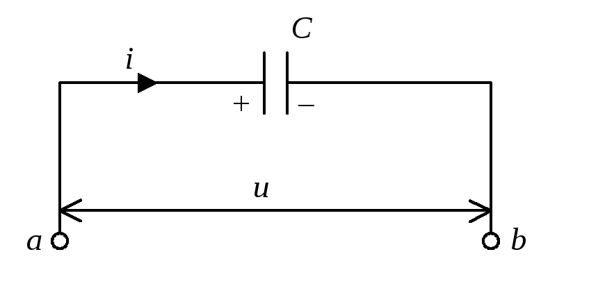
We now assume that the portion of the chain contains the capacitor of the capacitance C, whereby the resistance and inductance of the section can be neglected, and let us see by what law the voltage at the ends of the section will change in this case. Denote the voltage between points a and b across u and we will assume the charge of the capacitor q and current i Positive if they correspond to Fig. Then
 ,
,
![]()
and, consequently, 
 .
.
 ,
(1)
,
(1)
then the charge of the condenser is
 .
.
Integral constant q 0 here denotes an arbitrary constant charge of the capacitor not connected with the current oscillations, and therefore we set  . Consequently,
 .
(2)
.
(2)
|
Fig.4. Capacitor in alternating current circuit |
Fig.5. Current versus capacitor and voltage versus time |

Comparing (1) and (2), we see that with sinusoidal oscillations of the current in the circuit, the voltage across the capacitor also changes according to the cosine law. However, the voltage fluctuations on the capacitor lag behind the current oscillations by / 2. The changes in the current and voltage in time are shown graphically in Fig. The result obtained has a simple physical meaning. The voltage at the capacitor at any time is determined by the existing capacitor charge. But this charge was formed by a current that had previously occurred in an earlier stage of oscillations. Therefore, the voltage oscillations are delayed relative to the current oscillations.
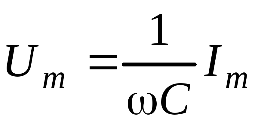
Formula (2) shows that the voltage amplitude on the capacitor is
 .
.
Comparing this expression with Ohm's law for a section of a circuit with a constant current ( 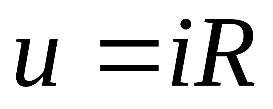 ), we see that the quantity
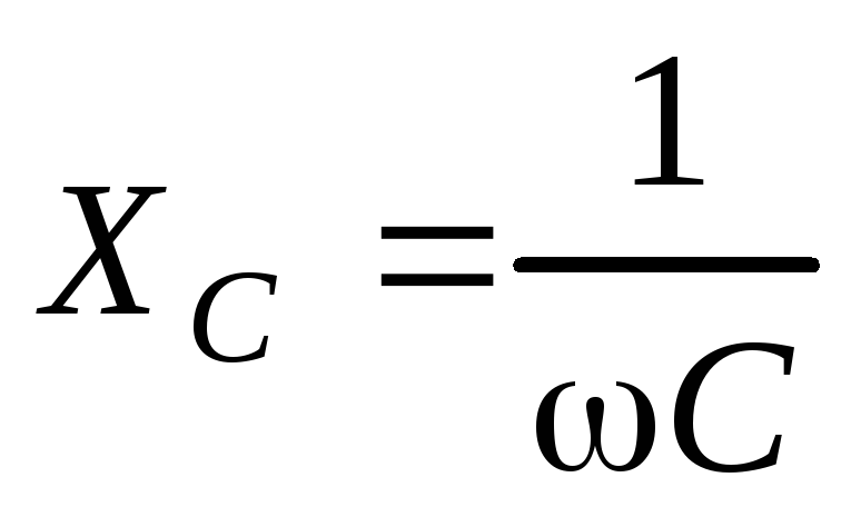
plays the role of the resistance of the circuit, it was called capacitive resistance. The capacitive resistance depends on the frequency and at high frequencies even small capacitances can represent a very small resistance for the alternating current. It is important to note that the capacitive resistance determines the relationship between the amplitude, not the instantaneous values of the current and voltage.
changes with time according to a sinusoidal law with a doubled frequency. During the time from 0 to T/ 4 the power is positive, and in the next quarter of the period the current and voltage have opposite signs and the power becomes negative. Since the average value for the period of fluctuations in the quantity  equal to zero, then the average AC power on the capacitor
  .
.
Coil inductance in alternating current circuit
Finally, we consider the third special case, when the section of the circuit contains only inductance. We denote by U stress between points aand b and we will consider the current I positive if it is directed from a to b (Fig. 6). If there is an alternating current in the inductor, an EMF of self-induction will arise, and therefore we must apply Ohm's law for the portion of the circuit containing this EMF:
 .
.
In our case R = 0, and the emf of self-induction
 .
.
 .
(3)
.
(3)
If the current in the circuit changes according to the law
,
|
Fig.6. Coil inductance in the circuit alternating current |
inductance and voltage from time to time |

 Fig.7. Dependences of the current through the coil
It can be seen that the voltage fluctuations on the inductance outperform the current oscillation by / 2 in phase. When the current strength, increasing, passes through zero, the voltage is already reaching a maximum, after which it begins to decrease; When the current becomes maximum, the voltage passes through zero, etc. (Fig. 7).
It follows from (4) that the amplitude of the voltage is
 ,
,
and, consequently, the quantity

plays the same role as the resistance of the circuit section. therefore  called inductive resistance. The inductive resistance is proportional to the frequency of the alternating current, and therefore at very high frequencies even small inductances can represent a significant resistance for alternating currents.
Instantaneous AC power
also, as in the case of an ideal capacitance, it changes with time according to a sinusoidal law with a doubled frequency. It is obvious that the average power per period is zero.
Thus, when an alternating current flows through an ideal capacitance and inductance, a number of general laws are revealed:
The current and voltage fluctuations occur in different phases - the phase difference between these oscillations is / 2.
The amplitude of the alternating voltage on the capacitance (inductance) is proportional to the amplitude of the alternating current flowing through this element

where X - reactive (capacitive or inductive resistance). It is important to keep in mind that this resistance connects not instantaneous values of current and voltage, but only their maximum values. The reactance is different from the ohmic (resistive) resistance in that it depends on the frequency of the alternating current.
The reactance does not dissipate the power (on average over the oscillation period), which means that, for example, an alternating current of a very large amplitude can flow through the capacitor, but there will be no heat release on the capacitor. This is a consequence of the phase shift between the current and voltage fluctuations on the reactive elements of the circuit (inductance and capacitance).
Resistive element, which is described in the considered frequency range by Ohm's law for instant currents and voltages
 ,
,
called ohmic or active resistance. At active resistances, power is released.
Laboratory work 6
Capacitor in alternating current circuit
Objective.Investigation of the dependence of the conductivity of a capacitor on the frequency of a sinusoidal current. Determination of the capacity of the capacitor and the dielectric constant of the substance filling the condenser.
Devices and equipment. Flat capacitor, dielectric plate, sinusoidal voltage generator, two digital voltmeters.
Theoretical part
In this paper, a flat capacitor is investigated, which consists of two flat conducting plates (plates) arranged parallel to each other, the charge of one plate q, and the other plate (- q). Distance between plates d is assumed small in comparison with the linear dimensions of the plates. In this case, the electric field between the plates can be considered homogeneous (Fig. 1), and the distribution of charges over the plates is uniform:
![]() , , (1)
, , (1)
where - the potential difference between the plates - the voltage on the capacitor, - the surface charge density, S is the area of the plate.
For the electric field in a capacitor, using the Gauss theorem, one can find
where is the permittivity of the substance between the plates, is the electrical constant, and then it follows from formulas (1) and (2) that the charge of the capacitor is proportional to the voltage applied to it
Coefficient of proportionality
called capacitance (or simply capacitance).
We note that, strictly speaking, the surface charge density s is not constant over the entire surface of the plate, but increases near its edges. Near the edges, the assumption of the homogeneity of the electric field is also violated, therefore formulas (1) used in the derivation of (4) are approximate. They are performed more precisely, the smaller the ratio d to the linear dimensions of the capacitor plates.
Schematically, the field of a flat capacitor, taking into account the edge effects noted above, is shown in Fig. 2. As can be seen from the figure, the field lines thicken near the edges of the capacitor, which is connected with the charge concentration at the edges of the plates. In addition, some lines of the field begin and end not on the internal, but on the outer surfaces of the plates. This means that some of the charge is located on the outer surfaces of the plates of the capacitor. We note that the total number of field lines in Fig. 1 and Fig. 2 is the same if the charges of the corresponding plates in Fig. 1 and Fig. 2.
A rigorous calculation of the capacitance of a flat capacitor, taking into account the edge effects, is a complex task. We give without derivation an approximate formula that takes into account the edge effects for a flat capacitor c round plates:
![]() , (5)
, (5)
where is the capacitance of the capacitor without taking into account the edge effects, r is the radius of the plate (). The second term in (5) takes into account the displacement of the charge to the edges of the plates, the third term is the partial displacement of the charge on the outer surfaces of the plates.
If the space between the plates of the capacitor is parallel to them, enter a flat plate of dielectric thickness with permeability, then the capacity of the capacitor will be equal to
![]() , (6)
, (6)
where C capacitance of the capacitor without dielectric.
Note that any pair of conductors, regardless of their shape and location, can be considered a capacitor. And in this case, the capacitance of the capacitor is called the proportionality coefficient between the capacitor charge (the charge of the positive electrode is called, the charge of the other capacitor plate is the same in magnitude but negative) and the potential difference between the plates. The capacitance of the capacitor depends on the geometric dimensions of the plates, their mutual arrangement and the dielectric constant of the medium.
Let us now consider the case when the capacitor is connected to an AC circuit. One of the directions of the current is assumed to be positive (it is indicated by an arrow in Fig. 3). We denote by charge of that of the capacitor plates, the direction from which to the other plate coincides with the positive direction of the current. Voltage between points a and b denote by u. Then
and, consequently,
If the current in the circuit changes according to the law
(- current amplitude, - cyclic frequency), then the capacitor charge is equal to
![]() .
.
Integral constant q 0 denotes an arbitrary constant charge of the capacitor not connected with the current oscillations, and therefore we set. Consequently,
![]() . (8)
. (8)
Comparing (7) and (8), we see that for sinusoidal oscillations of the current in the circuit, the voltage fluctuations on the capacitor lag behind the current oscillations by p / 2. The changes in the current and voltage in time are shown graphically in Fig.
Equation (8) shows that the amplitude of the voltage across the capacitor is
Comparing this expression with Ohm's law for a section of a circuit with a constant current (), we see that the quantity
plays the role of the resistance of the circuit, it was called capacitive resistance. The capacitive resistance depends on the frequency w, so at very high frequencies even small capacitances can represent a very small resistance for alternating current. It is important to note that the capacitive resistance determines the relationship between amplitude, and not instantaneous values of current and voltage.
In alternating current circuits, it is usually not amplitude, but effective values of current and voltage that are measured:
![]() ,
, ![]() .
.
where is the frequency. This relationship is verified experimentally.
A direct current can not exist in a circuit containing a capacitor. The circuit is then open because the capacitor plates are separated by a dielectric layer.
Alternating current is able to flow in a circuit containing a capacitor. This can be seen with a simple experiment.
We take sources of constant and alternating voltage, and the constant voltage at the terminals of the source will be equal to the effective value of the alternating voltage. The circuit consists of a condenser and an incandescent lamp (Figure 2.14) connected in series. When switched on with the DC voltage switch, the lamp does not light up. But when the alternating voltage is switched on, the lamp starts to glow if the capacity of the capacitor is large enough.
How can an alternating current flow through an open circuit? Here, a periodic recharging of the capacitor occurs under the action of an alternating voltage. The current flowing during recharging heats the lamp thread.
Let us find how the current strength in a circuit containing only a capacitor varies with time, if the resistance of the conductors and the capacitor plates can be neglected (Figure 2.15). + o
| O
FROM
C Voltage at the capacitor% -U.
equal to the voltage at the terminals of the circuit. Consequently,
sin cof. The capacitor charge varies according to the harmonic law:
q = CUm sin cof. (2.7.1)
The current strength is the derivative of the charge over time. If the charge q in formula (2.7.1) is the charge of that plate of the condenser, which occurs first for the chosen direction of traversal of the contour, then (see p. 64, § 2.3)
і =
Fig. 2.16
Consequently, the oscillations of the current strength outstrip the phase of the voltage oscillation by n / 2 (Figure 2.16). This means that at the moment when the capacitor starts charging, the current is maximal, and the voltage is zero. After the voltage reaches a maximum, the current becomes zero, and so on.
The amplitude of the current is: (2.7.3)
I = U (aC.
if we introduce the notation (2.7.4)
with C LC and instead of amplitudes of current and voltage, use their effective values, we get:
U
/ =
(2.7.5)
The quantity Xc, inverse to the product of the cyclic frequency by the capacity of the capacitor, is called the capacitive resistance. The role of this quantity is similar to the role of the active resistance R in Ohm's law (2.6.3). The current value of the current is related to the actual value of the voltage across the capacitor in the same way as the current and voltage in the portion of the DC circuit are connected according to Ohm's law. This allows us to consider the value of Xc as the resistance of a capacitor to an alternating current-the capacitive resistance.
The larger the capacity of the capacitor, the more the current of the charge exchange is, according to formula (2.7.3). This is easily detected by increasing the glow of the lamp as the capacitor capacitance increases. While the resistance of the capacitor to a direct current is infinitely large, its resistance to an alternating current has a finite value Xc. It decreases from
increase in capacity and increase in frequency.
This can be seen if a variable frequency alternator is used to supply the circuit shown in Figure 2.14. Gradually increasing the frequency of alternating current, one can observe an increase in the glow of the lamp. It is caused by an increase in the amperage due to a decrease in the capacitive resistance of the capacitor.
If the voltage from the capacitor is applied to one input of a two-beam oscilloscope and the voltage to the other input is proportional to the current in the circuit (this voltage is removed from the active resistance), then the oscillograms (time scans) of both oscillations will be simultaneously observed on the screen: and amperage. Such observations confirm the conclusion reached above that the oscillations of the current in the capacitor circuit are phase-shifted relative to the voltage oscillations by n / 2, as shown in Fig. 2.16.