Antipyretics for children are prescribed by a pediatrician. But there are situations of emergency care for fever, when the child needs to give the medicine immediately. Then the parents take responsibility and apply antipyretic drugs. What is allowed to give to infants? How can you bring down the temperature in older children? Which medications are the safest?
Marking in three digits.
| code | picofarads, pF, pF | nanofarads, nF, nF | microfarads, μF, μF | code | picofarads, pF, pF | nanofarads, nF, nF | microfarads, μF, μF | ||||
| 1.0 pF | 1000 pF | 1 nF | |||||||||
| 1.5 pF | 1500 pF | 1.5 nF | |||||||||
| 2.2 pF | 2200 pF | 2.2 nF | |||||||||
| 3.3 pF | 3300 pF | 3.3 nF | |||||||||
| 4.7 pF | 4700 pF | 4.7 nF | |||||||||
| 6.8 pF | 6800 pF | 6.8 nF | |||||||||
| 10 pF | 0.01 nF | 10000 pF | 10 nF | 0.01 uF | |||||||
| 15 pF | 0.015 nF | 15000 pF | 15 nF | 0.015uF | |||||||
| 22 pF | 0.022 nF | 22000 pF | 22 nF | 0.022 μF | |||||||
| 33 pF | 0.033 nF | 33000 pF | 33 nF | 0.033 uF | |||||||
| 47 pF | 0.047 nF | 47000 pF | 47 nF | 0.047 uF | |||||||
| 68 pF | 0.068 nF | 68000 pF | 68 nF | 0.068 μF | |||||||
| 100 pF | 0.1 nF | 100,000 pF | 100 nF | 0.1 uF | |||||||
| 150 pF | 0.15 nF | 150000 pF | 150 nF | 0.15 uF | |||||||
| 220 pF | 0.22 nF | 220000 pF | 220 nF | 0.22 uF | |||||||
| 330 pF | 0.33 nF | 330000 pF | 330 nF | 0.33 uF | |||||||
| 470 pF | 0.47 nF | 470000 pF | 470 nF | 0.47 uF | |||||||
| 680 pF | 0.68 nF | 680000 pF | 680 nF | 0.68 uF | |||||||
| 1000000 pF | 1000 nF | 1 μF | |||||||||
| marking | value | marking | value | marking | value | marking | value |
| A | 1.0 | J | 2.2 | S | 4.7 | a | 2.5 |
| B | 1.1 | K | 2.4 | T | 5.1 | b | 3.5 |
| C | 1.2 | L | 2.7 | U | 5.6 | d | 4.0 |
| D | 1.3 | M | 3.0 | V | 6.2 | e | 4.5 |
| E | 1.5 | N | 3.3 | W | 6.8 | f | 5.0 |
| F | 1.6 | P | 3.6 | X | 7.5 | m | 6.0 |
| G | 1.8 | Q | 3.9 | Y | 8.2 | n | 7.0 |
| H | 2.0 | R | 4.3 | Z | 9.1 | t | 8.0 |
"Directory" - reference Information on various electronic components: transistors, microcircuits, transformers,capacitors, lEDs etc. All reference Information electronic components electronic components.
· Tolerances
· Code marking
· Tolerances
· Condensers with a linear temperature dependence
· Condensers with nonlinear temperature dependence
· Code marking
· Marking of film capacitors for surface mounting of the firm "HITACHI"
Tolerances
Table 1
* -For capacitors with capacity< 10 пФ допуск указан в пикофарадах.
Δ = (δxС / 100%) [Ф]
Example:
Condensers with non-normalized TKE
table 2
Condensers with a linear temperature dependence
Table 3
| Designation of GOST | Designation international | TKE * | Literal code | Colour** |
| P100 | P100 | 100 (+130...-49) | A | red + purple |
| P33 | N | Gray | ||
| IGOs | NPO | 0(+30..-75) | FROM | the black |
| M33 | N030 | -33(+30...-80] | H | brown |
| M75 | N080 | -75(+30...-80) | L | red |
| M150 | N150 | -150(+30...-105) | R | Orange |
| M220 | N220 | -220(+30...-120) | R | yellow |
| M330 | N330 | -330(+60...-180) | S | green |
| M470 | N470 | -470(+60...-210) | T | blue |
| M750 | N750 | -750(+120...-330) | U | purple |
| M1500 | N1500 | -500(-250...-670) | V | orange + orange |
| M2200 | N2200 | -2200 | TO | yellow + orange |
* In brackets, the real spread is shown for imported capacitors in the temperature range -55 ... + 85 ° C.
** Modern color coding according to EIA. Color strips or dots. The second color can be represented by the color of the case.
Code marking
A. Marking in 3 digits
The first two digits indicate the value of capacity in pyrophagades (pf), the latter - the number of zeros. When the capacitor has a capacitance of less than 10 pF, the last digit can be "9". With capacities less than 1.0 pF, the first digit is "0". The letter R is used as a decimal point. For example, the code 010 is 1.0 pF, the code 0R5 is 0.5 pf.
Table 10
| Code | Capacity [pF] | Capacity [nF] | Capacity [μF] |
| 1,0 | 0,001 | 0,000001 | |
| 1,5 | 0,0015 | 0,000001 | |
| 2,2 | 0,0022 | 0,000001 | |
| 3,3 | 0,0033 | 0,000001 | |
| 4,7 | 0,0047 | 0,000001 | |
| 6,8 | 0,0068 | 0,000001 | |
| 100* | 0,01 | 0,00001 | |
| 0,015 | 0,000015 | ||
| 0,022 | 0,000022 | ||
| 0,033 | 0,000033 | ||
| 0,047 | 0,000047 | ||
| 0,068 | 0,000068 | ||
| 0,1 | 0,0001 | ||
| 0,15 | 0,00015 | ||
| 0,22 | 0,00022 | ||
| 0,33 | 0,00033 | ||
| 0,47 | 0,00047 | ||
| 0,68 | 0,00068 | ||
| 1,0 | 0,001 | ||
| 1,5 | 0,0015 | ||
| 2,2 | 0,0022 | ||
| 3,3 | 0,0033 | ||
| 4,7 | 0,0047 | ||
| 6,8 | 0,0068 | ||
| 0,01 | |||
| 0,015 | |||
| 0,022 | |||
| 0,033 | |||
| 0,047 | |||
| 0,068 | |||
| 0,1 | |||
| 0,15 | |||
| 0,22 | |||
| 0,33 | |||
| 0,47 | |||
| 0,68 | |||
| 1,0 |
B. Marking in 4 digits
Coding variants with 4-digit number are possible. But in this case, the last digit indicates the number of zeros, and the first three - the capacity in picofarads.
Table 11
B. Marking with 4 characters
The code contains four characters (letters and numbers), denoting capacity and operating voltage. The letter at the beginning indicates the working voltage, the subsequent signs are the nominal capacity in picofarads (pF), and the last digit is the number of zeros. There are 2 options for encoding capacity: a) the first two digits indicate the denomination in picofarads, the third - the number of zeros; b) the capacitance is indicated in microfarads, the sign m performs the function of a decimal point. Below are examples of marking capacitors with a capacity of 4.7 uF and operating voltage 10 V.
C. Marking in two lines
If the body size allows, then the code is placed in two lines: the top line indicates the capacity value, on the second line - the working voltage. The capacity can be indicated directly in microfarads (μF) or in picofarads (pF) with the number of zeros (see method B). For example, the first line - 15, the second line - 35V - means that the capacitor has a capacity of 15 mkF and an operating voltage of 35 V.
Marking of film capacitors for surface mounting of the firm "HITACHI"
http://www.radioradar.net/hand_book/hand_books/conder.html
Code marking
In accordance with IEC standards, in practice, four methods of encoding the nominal capacity are used.
Three-digit encoding
The first two digits indicate the capacitance value in picofarads (pF), the latter the number of zeros. When the capacitor has a capacitance of less than 10 pF, the last digit can be "9". With capacities less than 1.0 pF, the first digit is "0". The letter R is used as a decimal point. For example, the code 010 is 1.0 pF, the code 0R5 is 0.5 pF.
Table 1
* Sometimes the last zero is not specified.
Four-digit encoding
Coding variants with 4-digit number are possible. But in this case, the last digit indicates the number of zeros, and the first three - the capacity in picofarads (pF).
table 2
Color marking
In practice, color coding of constant capacitors uses several color-coding techniques
* Tolerance of 20%; it is possible to combine two rings and a point pointing to a multiplier.
** The color of the housing indicates the value of the operating voltage.
The output "+" can have a larger diameter.
For the marking of film capacitors use 5 color strips or dots:
The first three codes the value of the nominal capacity, the fourth - the tolerance, the fifth - the nominal operating voltage.
Tolerance marking
In accordance with the requirements of Publications 62 and 115-2 IEC (IEC) for capacitors, the following tolerances and their coding are established:
Marking of TKE
Marking in three digits.
The last digit "9" indicates the exponent of "-1". If the first digit is "0", then the capacity is less than 1pF (010 = 1.0pF).
| code | picofarads, pF, pF | nanofarads, nF, nF | microfarads, μF, μF | code | picofarads, pF, pF | nanofarads, nF, nF | microfarads, μF, μF | ||||
| 1.0 pF | 1000 pF | 1 nF | |||||||||
| 1.5 pF | 1500 pF | 1.5 nF | |||||||||
| 2.2 pF | 2200 pF | 2.2 nF | |||||||||
| 3.3 pF | 3300 pF | 3.3 nF | |||||||||
| 4.7 pF | 4700 pF | 4.7 nF | |||||||||
| 6.8 pF | 6800 pF | 6.8 nF | |||||||||
| 10 pF | 0.01 nF | 10000 pF | 10 nF | 0.01 uF | |||||||
| 15 pF | 0.015 nF | 15000 pF | 15 nF | 0.015uF | |||||||
| 22 pF | 0.022 nF | 22000 pF | 22 nF | 0.022 μF | |||||||
| 33 pF | 0.033 nF | 33000 pF | 33 nF | 0.033 uF | |||||||
| 47 pF | 0.047 nF | 47000 pF | 47 nF | 0.047 uF | |||||||
| 68 pF | 0.068 nF | 68000 pF | 68 nF | 0.068 μF | |||||||
| 100 pF | 0.1 nF | 100,000 pF | 100 nF | 0.1 uF | |||||||
| 150 pF | 0.15 nF | 150000 pF | 150 nF | 0.15 uF | |||||||
| 220 pF | 0.22 nF | 220000 pF | 220 nF | 0.22 uF | |||||||
| 330 pF | 0.33 nF | 330000 pF | 330 nF | 0.33 uF | |||||||
| 470 pF | 0.47 nF | 470000 pF | 470 nF | 0.47 uF | |||||||
| 680 pF | 0.68 nF | 680000 pF | 680 nF | 0.68 uF | |||||||
| 1000000 pF | 1000 nF | 1 μF | |||||||||
2. Marking in four digits.
This marking is similar to the one described above, but in this case the first three digits determine the mantissa, and the last one - the exponent of the base 10, to obtain a capacity in the picofarads. For example:
1622 = 162 * 102 pF = 16200 pF = 16.2 nF.
3. Alphanumeric marking.
With this marking, the letter indicates the decimal point and the designation (μF, nF, pF), and the digits indicate the capacitance value:
15p = 15 pF, 22p = 22 pF, 2n2 = 2.2 nF, 4n7 = 4.7 nF, μ33 = 0.33 μF
It is often difficult to distinguish the Russian letter "n" from the English "n".
Sometimes the letter R is used to denote a decimal point. Usually, microfarads are labeled in this way, but if there is a zero before the letter R, then these are picofarads, for example:
0R5 = 0.5 pF, R47 = 0.47 μF, 6R8 = 6.8 μF
4. Planar ceramic capacitors.
Ceramic SMD capacitors are usually or not marked at all except for the color (I do not know the color markings, if anyone will tell you - I will be happy, I know only that the lighter - the less capacity) or marked with one or two letters and number. The first letter, if it is the producer, the second letter denotes the mantissa in accordance with the table below, the figure is the exponent of the base 10, to obtain a capacity in the picofarads. Example:
N1 / according to the table, we determine the mantissa: N = 3.3 / = 3.3 * 101pF = 33pF
S3 / according to the table S = 4.7 / = 4.7 * 103pF = 4700pF = 4.7nF
| marking | value | marking | value | marking | value | marking | value |
| A | 1.0 | J | 2.2 | S | 4.7 | a | 2.5 |
| B | 1.1 | K | 2.4 | T | 5.1 | b | 3.5 |
| C | 1.2 | L | 2.7 | U | 5.6 | d | 4.0 |
| D | 1.3 | M | 3.0 | V | 6.2 | e | 4.5 |
| E | 1.5 | N | 3.3 | W | 6.8 | f | 5.0 |
| F | 1.6 | P | 3.6 | X | 7.5 | m | 6.0 |
| G | 1.8 | Q | 3.9 | Y | 8.2 | n | 7.0 |
| H | 2.0 | R | 4.3 | Z | 9.1 | t | 8.0 |
5. Planar electrolytic capacitors.
Code and color marking of capacitors
"Directory" - reference Information on various electronic components: transistors, microcircuits, transformers,capacitors, lEDs etc. All reference Information contains everything necessary for selection electronic components and engineering calculations, parameters, as well as pinning of housings, typical inclusion schemes and recommendations for use electronic components.
· Tolerances
· Condensers with a linear temperature dependence
· Condensers with nonlinear temperature dependence
· Code marking
· Code marking of electrochemical capacitors for surface mounting
· Marking of film capacitors for surface mounting of the firm "HITACHI"
· Tolerances
· Temperature coefficient of capacity (TKE)
Condensers with non-normalized TKE
· Condensers with a linear temperature dependence
· Condensers with nonlinear temperature dependence
· Code marking
· Code marking of electrolytic capacitors for surface mounting
· Marking of film capacitors for surface mounting of the firm "HITACHI"
Tolerances
In accordance with the requirements of Publications 62 and 115-2 IEC, the following tolerances and their coding are established for capacitors:
Table 1
* -For capacitors with capacity< 10 пФ допуск указан в пикофарадах.
Recalculation of tolerance from% (δ) to farads (Δ):
Δ = (δxС / 100%) [Ф]
Example:
The actual value of the capacitor labeled 221J (0.22 nF ± 5%) lies in the range: C = 0.22 nF ± Δ = (0.22 ± 0.01) nF, where Δ = (0.22 x 10 -9 [Ф] х 5) х 0.01 = 0.01 nF, or, respectively, from 0.21 to 0.23 nF.
Temperature coefficient of capacity (TKE)
Condensers with non-normalized TKE
table 2
* Modern color coding, Color strips or dots. The second color can be represented by the color of the case.
It is very important to know the capacitance of a capacitor, and at hand there are not always measuring instruments with which you can find out this capacity. Especially for these cases, code markings were invented. There are 4 main ways marking of capacitors:
- Code marking with 3 digits;
- Code marking with 4 digits;
- Alphanumeric marking;
- Special marking for planar capacitors.
3-digit code labeling of capacitors
For example, a capacitor with a designation of 153 means that its capacity is 15,000 pF.
| Code | Picofarads, pF, pF | Nanofarads, nF, nF | Microfarads, μF, μF |
| 109 | 1.0 pF | 0.0010nf | |
| 159 | 1.5 pF | 0.0015nf | |
| 229 | 2.2 pF | 0.0022nf | |
| 339 | 3.3 pF | 0.0033nf | |
| 479 | 4.7 pF | 0.0048nf | |
| 689 | 6.8 pF | 0.0068nF | |
| 100 | 10 pF | 0.01 nF | |
| 150 | 15 pF | 0.015 nF | |
| 220 | 22 pF | 0.022 nF | |
| 330 | 33 pF | 0.033 nF | |
| 470 | 47 pF | 0.047 nF | |
| 680 | 68 pF | 0.068 nF | |
| 101 | 100 pF | 0.1 nF | |
| 151 | 150 pF | 0.15 nF | |
| 221 | 220 pF | 0.22 nF | |
| 331 | 330 pF | 0.33 nF | |
| 471 | 470 pF | 0.47 nF | |
| 681 | 680 pF | 0.68 nF | |
| 102 | 1000 pF | 1 nF | |
| 152 | 1500 pF | 1.5 nF | |
| 222 | 2200 pF | 2.2 nF | |
| 332 | 3300 pF | 3.3 nF | |
| 472 | 4700 pF | 4.7 nF | |
| 682 | 6800 pF | 6.8 nF | |
| 103 | 10000 pF | 10 nF | 0.01 uF |
| 153 | 15000 pF | 15 nF | 0.015uF |
| 223 | 22000 pF | 22 nF | 0.022 μF |
| 333 | 33000 pF | 33 nF | 0.033 uF |
| 473 | 47000 pF | 47 nF | 0.047 uF |
| 683 | 68000 pF | 68 nF | 0.068 μF |
| 104 | 100,000 pF | 100 nF | 0.1 uF |
| 154 | 150000 pF | 150 nF | 0.15 uF |
| 224 | 220000 pF | 220 nF | 0.22 uF |
| 334 | 330000 pF | 330 nF | 0.33 uF |
| 474 | 470000 pF | 470 nF | 0.47 uF |
| 684 | 680000 pF | 680 nF | 0.68 uF |
| 105 | 1000000 pF | 1000 nF | 1 μF |
Condenser code marking 4 digits
When marking capacitors in this way, it is important to remember that the value obtained will be measured in picoFarads. For example, the marking of a capacitor 1002 will be deciphered as follows: 1002 = 100 * 10 2 pF = 10,000 pF = 10.0 nF. The last digit is the exponent of base 10. And the first three is the number that must be multiplied by 10 raised to a certain degree.
Alphanumeric marking
In this case, instead of a comma, the corresponding unit of measure is set (pF, nF, uF).
Example: 10p or 10p = 10 pF, 4n7 or 4n7 = 4.7 nF, μ 22 = 0.22 μF.
It is important to remember that the letter "n" is very similar to "n" and you do not need to confuse them. What quite often beginners are hams.
Sometimes, instead of uF, use the letter R.
For example: 6R8 = 6.8 uF

Marking of planar ceramic capacitors
Such capacitors are marked with two letters, the first is a capacitor manufacturer, and the second is in picofarads according to the table below.
In addition to alphanumeric marking, the method of digital marking with three or four digits according to IEC standards is used (Tables 2.5, 2.6).
With this method of marking, the first two or three digits indicate the capacitance in picofarads (pF), and the last digit indicates the number of zeros. At designation of capacities less than 10 pF, the last digit can be "9" (109 = 1 pF), for the designation of capacitances 1 pF and less than the first digit will be "0" (010 = 1 pF). The separator point is the letter R (0 R 5 = 0.5 pF).
When marking capacitor capacitors in microfarads, digital marking is used: 1 - 1 μF, 10 - 10 μF, 100 - 100 μF. If it is necessary to mark fractional capacitance values, the letter R is used as a separating point: R 1 - 0.1 μF, R 22 - 0.22 μF, 3 R 3 - 3.3 μF (for capacitance in μF before the letter R digit 0 It is not put, but it is put only for the designation of capacities less than 1 pF).
After the designation of the container, an alphanumeric symbol indicating the permissible deviation of the capacitance of the capacitor can be applied in accordance with Table. 2.4.
Table 2.5. Encoding nominal capacity capacitors three figures
Picofarads (pF, pF)
Nanofarads (nF; nF)
Microfarads (μF)
Capacity
Picofarads ( pf ; pF)
Nanofarads ( nF ; nF)
Microfarads ( uF ; mF)
Table 2.6. Encoding nominal capacity capacitors four figures
Capacity
Picofarads (pF, pF)
Nanofarads (nF; nF)
Microfarads (μF
TKE (temperature coefficient of capacitance) is a parameter of a capacitor that characterizes the relative change in capacitance from the nominal value when the ambient temperature changes. This parameter is usually expressed in parts per million capacitor capacitance per degree
(10 / -6 / ° C). TKE can be positive (indicated by the letter "P" or "P"), negative
("M" or "N"), close to zero ("MP") or unregulated ("H").Condensers are manufactured with different types of dielectrics in the TKE: NPO groups, X 7 R, Z 5 U, Y 5 V, and others. The NPO (COG) dielectric has a low dielectric permittivity, but good temperature stability (TKE is close to zero). SMD capacitors of higher denominations made using this dielectric are the most expensive. The dielectric of the X 7 R group has a higher dielectric constant, but less thermal stability.
The dielectrics of the Z 5 U and Y 5 V groups have a very high dielectric constant, which makes it possible to fabricate capacitors with a large capacitance value, but with a wide range of parameters. SMD capacitors with dielectrics of groups X 7 R and Z 5 U are used in general-purpose circuits.

When assembling self-made electronic circuits you inevitably encounter the selection of the necessary capacitors. Moreover, for the assembly of the device you can use condensers that have already been used and worked for a time in electronic equipment. Naturally, before secondary use is necessary check capacitors , especially electrolytic , which are more prone to aging.
When selecting capacitors of constant capacitance, it is necessary to understand the labeling of these radio elements, otherwise in case of an error the assembled device either refuses to work correctly or does not work at all. The question is how to read the marking of the capacitor?
The capacitor has several important parameters that should be considered when using them.
First, this capacitor nominal capacitance. Measured in fractions of Farada.
The second is admission. Or in another way permissible deviation of nominal capacity from the specified. This parameter is rarely taken into account, since in radio equipment used radio elements with a tolerance of up to ± 20%, and sometimes more. Everything depends on the purpose of the device and the features of the particular device. In principle, this parameter, as a rule, is not indicated.
The third, which is indicated in the marking, is allowable operating voltage. This is a very important parameter, it should be paid attention if the capacitor is to be operated in high-voltage circuits.
So, let's figure out how to mark capacitors.
One of the most popular capacitors that can be used is capacitors of constant capacity K73 - 17, K73 - 44, K78 - 2, ceramic KM - 5, KM - 6 and the like. Also analogues of these capacitors are used in electronic equipment of imported production. Their labeling is different from domestic.
Condensers of domestic production K73-17 are film polyethylene terephthalate protected capacitors. On the body of data capacitors The marking is applied by an alphanumeric index, for example 100nJ, 330nK, 220nM, 39nJ, 2n2M.

K73 series capacitors and their marking
Marking rules.
Capacities from 100 pF and up to 0.1 μF are labeled in nanofarads, indicating the letter H or n.
Designation 100 n Is the value of the nominal capacity. For 100n - 100 nanofarads (nF) - 0.1 microfarads (μF). Thus, a capacitor with an index of 100n has a capacity of 0.1 μF. For other notation is similar. For example:
330n - 0.33 uF, 10n - 0.01 uF. For 2n2, 0.0022 μF or 2200 picofarads (2200 pF).
You can find the marking type 47 HC. This entry corresponds to 47 nK and is 47 nanofarads or 0.047 μF. Similarly, the 22HC is 0.022 uF.
In order to easily determine the capacity, it is necessary to know the designations of the basic lobular units - milli, micro, nano, pico and their numerical values. Read more about this.
Also in the marking of capacitors K73 there are such symbols as M47C, M10C.
Here, the letter M conditionally means microfarad. The value of 47 is after M, ie the nominal capacity is the bottom part of the microfarad, i.e. 0.47 μF. For M10C, 0.1 μF. It turns out that the capacitors labeled M10C and 100nJ have the same capacity. Differences only in the record.
Thus, a capacitance of 0.1 μF and higher is indicated with the letter M, m Instead of a decimal point, an insignificant zero is omitted.
The nominal capacitance of domestic capacitors up to 100 pF is indicated in picofarads, setting the letter P or p after the number. If the capacity is less than 10 pF, then the letter R and two digits. For example, 1R5 = 1.5 pF.
On ceramic capacitors (such as KM5, KM6), which are small in size, usually only a numeric code is indicated. Here, take a look at the photo.

Ceramic capacitors with marked numeric code capacity
For example, 224 matches the value 22 0000 picofarad, or 220 nanofarads and 0.22 uF. In this case, 22 is the numerical value of the nominal value. The number 4 indicates the number of zeros. The resulting the number is the value of the capacity in picofarads. Recording 221 means 220 pF, and record 220 - 22 pF. If the code uses four digits, the first three digits are the numeric value of the nominal value, and the last, the fourth, is the number of zeros. So at 4722, the capacity is 47200 pF - 47.2 nF. I think we got it sorted out.
The allowable capacity deviation is marked either by a percentage (± 5%, 10%, 20%) or by a Latin letter. Sometimes it is possible to meet the old designation of a tolerance encoded by a Russian letter. The permissible capacity deviation is similar to the tolerance for the resistance value y resistors.
Letter code for the deviation of the capacity (tolerance).
So, if the capacitor with the following marking is M47C, then its capacitance is 0,047 μF, and the tolerance is ± 10% (according to the old marking with Russian letter). To meet a capacitor with a tolerance of ± 0.25% (by lettering with a Latin letter) in household equipment is quite difficult, so a value with a greater margin of error is chosen. Basically, household appliances use capacitors with a tolerance H, M, J, K. The letter designating the tolerance is indicated after the nominal capacity, like this 22n K, 220n M, 470n J.
Table for decoding the conditional letter code for the permissible deviation of the capacity.
| Dlowering in% | Bnomenclature | |
| lat. | rus. | |
| ± 0.05p | A | |
| ± 0.1p | B | F |
| ± 0.25p | C | Have |
| ± 0.5p | D | D |
| ± 1.0 | F | R |
| ± 2.0 | G | L |
| ± 2.5 | H | |
| ± 5.0 | J | AND |
| ± 10 | K | FROM |
| ± 15 | L | |
| ± 20 | M | AT |
| ± 30 | N | F |
| -0...+100 | P | |
| -10...+30 | Q | |
| ± 22 | S | |
| -0...+50 | T | |
| -0...+75 | U | E |
| -10...+100 | W | YU |
| -20...+5 | Y | B |
| -20...+80 | Z | A |
Marking of capacitors by operating voltage.
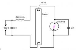
An important parameter of the capacitor is also the permissible operating voltage. It should be taken into account when assembling self-made electronics and repairing household radio equipment. Thus, for example, repair of compact fluorescent lamps it is necessary to select a capacitor for the appropriate voltage when replacing the failed ones. It is not superfluous to take a capacitor with a reserve of working voltage.
Normally, the value of the permissible operating voltage is indicated after the nominal capacity and tolerance. Indicated in volts from the letter B (old marking), and V (new). For example, this is the case: 250V, 400V, 1600V, 200V. In some cases, the letter V is omitted.
Sometimes the encoding is done using the Latin letter. For decoding it is necessary to use the table of letter coding of working voltage.
| Hrated operating voltage, B | Bspecial code |
| 1,0 | I |
| 1,6 | R |
| 2,5 | M |
| 3,2 | A |
| 4,0 | C |
| 6,3 | B |
| 10 | D |
| 16 | E |
| 20 | F |
| 25 | G |
| 32 | H |
| 40 | S |
| 50 | J |
| 63 | K |
| 80 | L |
| 100 | N |
| 125 | P |
| 160 | Q |
| 200 | Z |
| 250 | W |
| 315 | X |
| 350 | T |
| 400 | Y |
| 450 | U |
| 500 | V |
Thus, we learned how to determine the capacitance of the capacitor by marking, and also got acquainted with its basic parameters as we went along.
Marking of imported capacitors is different, but in many respects corresponds to the stated.