Antipyretics for children are prescribed by a pediatrician. But there are situations of emergency care for fever, when the child needs to give the medicine immediately. Then the parents take responsibility and apply antipyretic drugs. What is allowed to give to infants? How can you bring down the temperature in older children? Which medications are the safest?
The optimal variant of connecting the object to the power grid must be selected in advance, at the stage of obtaining the technical specification for electricity supply. External power supply .. Situational plan .. Air line (VL) 0,4 kV .. Cable line (CL) .. Subscriber branch .. Wires and fittings SIP-4 .. Input device .. Re-earthing of PEN-conductor .. Relay of the maximum voltage RN113 .. Application of the protection device UZM-51M .. Grounding system TN-C-S .. Stormovervoltage .. SPD.
Source documents for external power supply design
The main document on the basis of which the object is connected to electric grids is the technical conditions (TU) for connection. Therefore, the first thing an owner of an object should take care of is the receipt of technical specifications. Based on this document, a power supply project is being developed.
Air lines (VL) with a voltage of 0.4 kV are found in almost every village where cottages and low-rise private houses are supplied from such lines. As a rule, these lines are built along the streets and from the supports of these lines a scheme of external power supply for residential houses is being built.
The length of the branch from the overhead line to the entry into the building should be no more than 25 meters. At a greater distance, an additional support is installed. In this case, the span between the overhead line and the additional support can be made with a bare wire, but an insulated wire is used from the last support to the building entrance. If the object is located at a considerable distance from the already constructed overhead lines, in the technical conditions, it may be envisaged to erect such a line at the expense of the owner. In accordance with the specification, a 0.4 kV HVL project must be completed, without which the connection to the power grid is impossible, since the existence of the project is stipulated by the current rules.
In this case, the designer will need another document - a situational plan for the construction site of the 0.4 kV overhead line. A situational plan is a topographic plan of the terrain where construction is planned, performed on a scale of 1: 500 or 1: 1000.
It is carried out on the basis of planning projects of the district, as well as on the materials of engineering and geodetic surveys.
On the situational plan, all existing ground and underground objects (buildings, roads, HVL networks, communication lines, cable routes, water supply and sewerage networks, gas pipelines, etc.), vertical elevations, as well as the directions of the light and the rose winds.
Thus, the following source documents are required for the design of an external power supply:
- technical conditions (specifications) for connection to electric grids;
- technical conditions for the organization of accounting (can be combined with the specification for accession);
- situational plan (with the designation of supports, from which the connection is envisaged);
- the plan of the house itself (indicating the installation location of the input device)
An air or cable line?
It should be noted that, despite the seeming simplicity of the arrangement of overhead lines, their application is not always the best option. Especially when it comes to power supply facilities located within the city. Firstly, overhead power lines in urban conditions are more difficult to maintain, since it is necessary to provide access roads for special transport, and this is due to the need to obtain a number of municipal permits. Often, even for the installation of poles in the settlement permission to obtain is not always possible. Air lines also lose cable lines in reliability. If the design of the cable line and the subsequent gasket are made correctly, then the influence of the environment on the line is reduced to zero, while the overhead line constantly experiences temperature changes and wind loads. The result of these influences can be icing, unacceptable sagging and, as a result, breakage of the wires of the overhead line. In addition, an air line can strike lightning, which should always be considered when designing a VL.
There are a number of limitations in the design of cable lines (CL).
In particular, around the underground cables laid underground, there is a security zone, the work in which is regulated by the rules for the protection of electrical networks. Throughout the route, the cable line must be protected from mechanical damage. When laying KL in urban conditions, the distance to the carriageway (1 m), to the nearest building (0.6 m) and so on are normalized. In general, if it is a question of building electric grids in the city, the main problems are coordination. You lay the cable through the territory - you need to coordinate it with the land owner, cross othercommunication - must be coordinated with the owners of communications, cross the road - it is necessary to coordinate the intersection and so on. During the reconciliation process, the initial version of the project may change (sometimes very significantly).
The basic rules for the installation of cable lines are established PUE izd.7 ch. 2.3. When laying cables in the ground, reference should be made to the normative document series A5-92 (Laying cables with voltage up to 35 kV in trenches).
Obtaining specifications
Studying the various possible options for connecting to electric grids, the most economical and simple solution is chosen. It should be noted that the optimal variant of connecting the facility to the power grid must be selected in advance, at the stage of obtaining the technical specification for electricity supply. To do this, a preliminary survey of existing networks is made and a decision is made based on their results. Read more about preparing an application for a technical specification in article .
The general requirement when connecting the house to external electric grids is the involvement of the personnel of the power supply organization. At its site, the consumer fulfills the technical work conditions provided for by the technical conditions.
Consider the project of external power supply of a residential house from the existing 0.4 kV overhead line (subscriber branch).A subscriber branch is called the line segment from the main trunk of the main overhead line to the entrance to the house. According to the existing norms, the branch is considered to be part of the overhead line.
What are the subscriber branches?
Most often, to a low-rise private house, a branch is produced by two wires - phase and zero (single-phase input). More rarely - four wires (three-phase input). Sometimes there is a need for a three-wire branch (two-phase input) - two phase conductors and one zero (for example, entry into a semi-detached house). In this case, the zero wire is common, the phase wires are necessarily different.
For the input device in the house, usually the armature and wires of SIP 4 or SIP 5 with veins of the same cross section 16 mm2 are usually used. The use of aluminum wires of a smaller cross section is prohibited by the PUE (paragraph 2.4.14). The branch from the backbone FIR (made by cable SIP) is carried out with the help of one-sided piercing clamps. When using such clamps, the CIP conductors need not be cleaned (the insulation is pierced), and the clamping force is regulated by a discontinuous hexagon head.
A branch from a high-voltage line with non-insulated wires (AC type) is carried out with the help of special tapping terminals for connecting the SIP to bare wires. On the approach to the outer wall of the house, the CIP cable is fixed using a standard kit consisting of an anchor clamp and a bracket.
Concerning the choice of wires and fittings for self-supporting insulated wire
 In the late nineties, only a few designers of 0.4 kV overhead transmission lines in electrical networks and in design organizations had catalogs on wires and fittings of SIP, and then only European manufacturers. They also delivered their products to the Russian market - there were simply no other.
Responding to market demand, Russian cable plants quickly mastered the production of SIP wires of different sections and fittings for their installation, and in recent years the demand for these products has been gradually shifting in favor of Russian producers. Their products compete successfully with leading European brands ENSTO, NILED, TYCO due to the optimal quality / price ratio. For example, trademarks REC and HUBIX SARATOV fully comply with the European standard, but advantageously differ from imported analogues at a lower price.
On the company's website HUBIX SARATOV
you will also find the selection tables for linear fittings for the installation of SIP-4 and SIP-5.
Characteristics of the object:
Residential house with an attic with a total area of 250m2, located in the depth of the plot. In the foreground next to the entrance gate is a garage. The nearest support of the 0.4 kV overhead line with uninsulated wires is installed behind the fence of the site at a distance of 13m from the garage. The cabinet of the input device with the accounting unit is planned to be installed on the externalwall of the garage at a height of 1.7 m from the ground.
Estimation of the existing 0.4 kV overhead line
Estimation of the state of networks, as already said, is done at the stage of obtaining technical specifications and it is necessary for us to make the right design decisions. The main results of the survey of the main 0.4 kV overhead line:
- concrete supports with a bare wire AS 4х50 мм² are installed;
- the line served;
- On the line there are repeated zero groundings.
The backbone of 0.4 kV overhead line is not new (for insulated networks the insulated wire of SIP has already become the standard), but the supports are concrete, therefore they will last for a long time. When examining the poles on some of them, a re-grounding of the PEN conductor was detected. Passages for wires were made in the way of passing overhead lines in the crowns of trees. This indicates that the line is maintained and in good condition.
Estimation of the state of the networks is very important for making design decisions. Informed, then armed. We found that the VL is in good condition. Nothing interferes with making air entry into the house, and at the input - re-earthing the PEN conductor in accordance with the requirements PUE (paragraph 1.7.102).
For what it is necessary to re-ground the PEN conductor
In accordance with PUE The air lines (bushings) must be protected against lightning overvoltages. Here we are dealing with very short (≤ 100 μs) and high (up to 25 kA) overvoltage pulses. To reduce the amplitude of the lightning impulse to the minimum values, surge protection devices (SPD) of Class I are designed, the installation of which is regulated on air inlets in buildings clause 7.1.22 of the PUE.
The SPDs are connected between the phase and the SGS of the input device, which must be connected to the grounding device. The PEN wire of SIP 4 is also connected to the GDS. In accordance with p. 2.4.47 of the PUE protective grounding devicewe are entitled to combine the lightning overvoltage with the repeated earthing of the PE conductor.
It should be noted that for domestic appliances installed in the house, the level of protection class I (Up ≤ 4 kV) is not enough, so the house is allocated a second lightning protection zone and at the boundary of 1 - 2 zones installed UZIP class II. It is installed in an internal switchboard or in a special shield next to it. Installation of such SPDs should provide in zone 2protection level Up ≤ 2.5 kV. For the correct sequence of operation, between devices of different classes there should be a distance on the power cable of at least 10 meters in length.
Next, we need to organize a grounding system TN-C-S and enter the protective conductor PE into the house, since the internal networks are three-wire. The division of the PEN into a zero working N and protective PE conductors is performed on the GDS, which is connected to the ground loop.
The requirement for the installation of a metering station in the input device also leaves us no alternative for re-grounding the PEN conductor, since the PEN separation must be performed before the metering devices.
Thus, it is always necessary to aim at re-grounding the PE conductor at the entrance to the house, as this allows to build a TN-C-S system, which is safer than other grounding systems.
It is also possible to exclude from consideration the likelihood of breaking (zeroing) zero on the line. This can happen on old overhead lines. In this case, re-grounding the PEN to its own ground loop ensures protection of electrical equipment and improves the reliability of power supply. At the same time, our re-grounding can become a working zero for other consumers of this line, which can lead to its overheating. Increasing the conductor cross-section to the section of the main line solves the problem, but it is not always possible to do this.
What should be done in all cases is to connect the PEN connection of the conductor to the grounding device outside the building so that there is no uncontrolled conductor connecting the grounding device to the grounded power supply wire in the shield.
Protection against unacceptable voltage fluctuations
In accordance with the recommendations PUE (item 7.1.21) on the inputs to the apartment houses, a maximum voltage relay (RN) should be installed to protect equipment and devices from unacceptable voltage fluctuations in the network and overvoltages that occur when the PEN conductor breaks.
The installation of a maximum voltage relay does not exclude, but only supplements the re-grounding of the PE conductor in terms of safety. Do not forget that unacceptable (more than 10%) voltage deviations, not necessarily associated with power failures (for example, voltage drops due to insufficient transformer power, the inclusion of high-powerwelding machines, transient switching overvoltage, etc.), also sometimes happen and can lead to the failure of expensive electrical equipment.
Single-line power supply scheme
 Taking into account the condition of the existing 0.4 kV overhead line, a single-line electricity supply scheme for a residential building is being developed, which is attached to the application for obtaining a technical specification for connection to electric grids. The boundary of the balance sheet andoperational responsibility passes through the point of connection in the remote accounting point. The single-line diagram also shows the FV and the contacts of the maximum voltage relay.
More details on single-line power supply scheme can be read The single-line power supply scheme is presented on fig. 1
.
Fig. 1
Schematic of electric input device
On the basis of a single-line scheme, an electrical schematic of the input device is implemented. The electrical diagram of the input device is shown on fig. 2 . Let's consider it in more detail.
Here, the separation of the PEN conductor into a zero working N and a zero protective PE occurs on the main ground bus (GZSH). As GZSH the PE bus of the input device is used - the remote point of the electric power accounting.
After the load disconnector, a single-phase SPD of class 1 (spark gap) from the company "Hakel Ros" is connected between the phase and the GZSH. Class 1 SPDs are installed in 1 lightning protection zone and are designed to protect power distribution systems up to 1000 V with air power inputs from impulse overvoltages, the sources of which are:
Direct lightning strikes (PIP) in the lightning protection system of the facility or an air line in the immediate vicinity before entering the facility;
Lightning strikes in a radius of up to several kilometers near objects and incoming communications.
The used HS50-50 RW is capable of removing current pulses up to 50 kA.
The voltage relay RN-113 is also installed in the meter board. It allows you to protect single-phase loads from unacceptable voltage fluctuations in the network and subsequent automatic switching after restoring the network parameters. And also protects against the disappearance of zero on the overhead line in case of its "burn-out".
Fig. 2 One of the most unpleasant accidents in networks is the breakage or "burning off" of zero.
All the loads in our house are included between phase and zero. If there is no re-grounding of the PEN at the input, the electrical appliances included in the network on the zero side are not connected to the ground, but through the broken PEN are connected to other, neighboring electrical appliances and only through them to the phase, only the other. A closed circuit is obtained: say, phase A is a broken zero-phase B. Theoretically, the voltage in the sockets can vary from 0 to 418 V. Practically - for tens of volts in one direction or another. Depends on which phase you are connected to. On an unloaded phase, the voltage increases in an avalanche manner and can exceed 300 V. If heavily loaded, the voltage becomes extremely low. This is called a phase skew. Between the two phases, electrical appliances of different consumers are turned on. How many electrical appliances will burn and which owners - this is who will be lucky.
One way to protect electrical equipment against zero loss is to re-ground the PEN conductor at the input, as mentioned above.
The second way to protect the electrical equipment from zero loss is to install a maximum voltage relay. Both these protections can be applied separately or complement each other.
Before the PEN re-grounding device, it is necessary to evaluate the condition of the overhead line for the presence on it
re-grounding zero.
Repeated grounding of PEN must be done in the input device installed outside, outside the apartment building.
The voltage relay PH-113 allows to disconnect single-phase load of any power.
When the load power is higher than 7 kW (as in this project), the consumers are disconnected by a two-pole contactor, the output circuit of the RN-113 relay is included in the coil supply circuit.
If the load is less than 7 kW (no more than 32 amps), the contactor will not be needed, the relay will shut off and turn on the load with its power contacts.
The presence of a voltmeter based on a three-digit digital indicator makes it very convenient to set the limits for the operation of the voltage relay. In operating mode, the voltmeter indicates the actual value of the input voltage and the status of the output relay (on / off).
Switches on the front panel can be set several modes of the relay:
minimum voltage relay;
maximum voltage relay;
the relay of the maximum and minimum voltage (load disconnection when the voltage is increased or decreased above the permissible voltage).
Set the voltage of the relay can be in the range 160 ... 280V.
The automatic restart time of the PH113 relay can be set between 5 and 900 seconds.
On the application of USM-51M
In connection with the topic under consideration it is important to say a few words about the application of the UZM-51M protection device, which is often used.
This protection device performs almost the same functions as the RN-113, but unlike it has more powerful power contacts - it can switch the current to 63A.The second difference between the UZM-51M is that it has a built-in varistor for damping the overvoltage pulses. It turns out 2 in 1 - voltage relay and SPD. Of the disadvantages - the lack of a voltmeter.
Now about the application. The main criterion in choosing a protection device is its reliability and safety. Manufacturer - the company MEANDR, gives a detailed technical description (TO) of the protection device on its website. Let's try to understand the conditions of USM-51M application. Of the technical characteristics, we are interested in those parameters that can affect the safety of electrical networks:
- maximum absorption current (single pulse 8 / 20μs) - 10 kA;
- maximum absorption current (repetitive pulses 8 / 20μs) - 8 kA.
This is the maximum current in the pulse, which can pass through the varistor and remain in the operable state.
Lightning discharges are characterized by repetitive pulses.
In suburban homes, the value of the lightning discharge current is assumed equal to 100 kA. Based on the worst case scenario, it is believed that the entire lightning current will go through the power cables. With a direct impact on the air line, the current will roughly flow in equal parts to the source (TP) and into the house. Thus, if in a VL or a lightning detector hit a 100 kA discharge, then 50 kA will pass through the wires entering the house, divided by the number of inputs. That is, with two incoming wires on each of them you can get a current 25
kA.
It is already clear that the installation of UZM-51M in facilities with air inlets should be limited or additional ways of protection.The manufacturer does not say anything about it. The only mention in the TOE about the purpose of the device is "in an apartment, office, etc."I.e, without any restrictions UZM-51M can be used on sites, to which the power supply is supplied by underground cables.
In private houses, cottages, cottages are mainly arranged air inlets.
It is not difficult to understand what will happen if there is a direct lightning strike in the immediate vicinity of the air inlet (Iimp = 25 kA). The impact of powerful overvoltage pulses can lead to thermal breakdown of the varistor and failure of the SPM. This is at best, and perhaps even more serious consequences. It turns out that the varistor itself still needs to be protected - put in front of it (at the input) an SPD of class I. Then the residual lightning overvoltage (Up ≤ 4 kV) will be delivered to the switchboard, which will belimit the varistor of the SPM to a minimum level.
We draw conclusions:
- UZM-51M is not intended for use in electrical installations with air power inputs without additional protection.
- If you use USM-51M, always, regardless of the thunderstorm activity of the region, be installed outside on the air inlet in the house of the SPD class I or the gate arrestor RVN-250.
Branch plan from 0.4 kV overhead line
The branch plan from 0.4 kV overhead transmission line is presented onfig. 5.
External power supply of the projected residential building is provided from the existing 0.38 kV overhead line, passing 13 meters from the house. The branch from the 0.38 kV overhead line to the residential building is made with a self-supporting insulated wire SIP-4 2x16.
The project provides:
- installation on the external wall of the garage of the remote accounting point;
- installation of the SIP-4 wire from the support №58 to the accounting board;
- laying of cable ВВГнг 3х10 from the control panel to the switchboard SHCHRN.
A branch from non-insulated wires AC (phase and zero) and fixing the wire SIP-4 2х16 on the facade of the garage is made with the help of HUBIX SARATOV fittings. The cross-section of the SIP wire is selected for mechanical strength according to PUE (paragraph 2.4.14). Cable SIP-4 is entered into the electricity meter in the corrugated pipe. From the meter board to the switchboard SHCHRN the power supply is laid with a cable BBNng 3х10 in corrugated pipe. The cable line is protected by a circuit breaker BA47-100 D50.
Fig. 5 Electricity accounting
The electricity is accounted for in a remote accounting station of the type SHU1-50A with a single-phase electronic meter of the 1-grade accuracy of SEA11M or another with a lower limit of operating temperatures of at least -40 ° C.
In the remote accounting point, an input load break switch, surge protection device (SPD), a maximum voltage relay (RN), a bus of zero operating N and protective PE conductors are also installed. Andautomatic switches of outgoing lines.
The meter reading is read through the window in the door, the cabinet door is sealed.
Degree of protection IP54.
If you liked the article and appreciate the investments made in this project –
you have the opportunity to make a feasible contribution to the development of the site on the page
To simplify the drawings and their perception, different methods are used. Often, a single-line electricity supply scheme for a residential building, enterprise or private structure is used, which contributes to the development and understanding of complex projects.
What is a single-line diagram
The main feature of the single-line scheme is that this circuit diagram consists entirely of single lines for designating three-phase or two-phase circuits. This approach allows us to provide more appropriate use of technical documentation. Those. In one technical project, you can put several different drawings that are not related to each other.
Photo - single line diagram
Exist two types of such schemes:
- Estimated;
- Executive.
Calculated single-line diagram The room is mainly used after the ready miscalculation of the loads necessary to power an individual building. Sometimes it is designed after the need for wires and feed cables has been calculated.

Executive principal single-line diagram It is used to recalculate the current energy supply system. In most cases, this is necessary to make major changes to an already established project.

Photo - single-line substation diagram
Video: example of work with loop power supply
How to perform a single-line scheme
Electric single-line diagram of electricity supply of an apartment, house, private enterprise is carried out according to the requirements of GOST 2.702-75. According to the rules, you should get an image of 3 phases feeding the network of a particular room and the line of group networks that depart from the supply. The scheme does not need to be detailed in detail, its main goal is to give an idea of the general design of the electric supply system.

Photo - Schematic diagram of the substation
It is thanks to this information flow that the result is a fairly simple drawing that clearly conveys the main parameters of the power network. Many novice electricians can doubt the effectiveness of such drawings, because it seems that it is unclear how to display them then three-phase or two-phase power.
It's very simple: near the line that determines the multiphase power is put a figure and a crossed out stroke, as in the photo below. The figure in this scheme is responsible for determining the number of phases, and the line crossed out with oblique segments is the phase definition.
In addition to displaying individual wires, it is also important to depict additional electrical circuit parts in the drawing. To designate the apartment's RCD, contactors, switches and other additional elements, you also need to familiarize yourself with GOST 2.709, which is provided both in PDF and in plain text. This document specifies the generally accepted drafting of such elements.
Consider example of a single-line apartment scheme (you can also use it to power the house):

Photo - an example of a single-line scheme
To protect the multicast lines from overload and the general circuit of the room from electrical faults, automatic switches are used. They, in turn, on the drawing "secure" devices of overcurrents. The circuit must necessarily include not only its main components (input, ground, RCD), but also sockets, light switches in the rooms.
In the drawing above you can pay attention to the fact that there are no figures near the crossed lines with oblique strokes. Instead, the phase is determined by the number of strokes. If the diagram shows 2 strokes - then the power supply is two-phase, if 3 - then, respectively, three-phase. But in this case single-phase wiring is denoted by one line with one stroke.
This connection perfectly demonstrates single-line circuit of transformer KTP:

Photo - single-line diagram of transformer ktp
Examples of what, which should include single-line typical scheme of power supply of a polyclinic, an apartment, a suburban or country house, a plant or other premises:
- The point where the object is connected to the electrical network;
- All ASPs (input and distribution devices);
- The point and mark of the device used to connect the room (in most cases, the shield parameters are also needed);
- It is necessary not only to draw a power cable, but also to note on its diagram the cross section and the mark, sometimes the masters mark the denomination;
- The project should contain data on the nominal and maximum currents of equipment that is used at the facility.
It is also very important to use approximate design loads that can be maximum for a particular power supply network (ATS) of your village, city. The execution rules can vary depending on the requirements for specific premises.
You should pay attention to any little things, because the main requirements for the project are put forward by the electricity supply company. It is the single-line diagram of the power supply of the enterprise, the house, the shop is the basic document according to GOST, which is responsible for the operational responsibilities of different parties. In particular, it is needed to connect to a home network with an ATS:

Photo - house with aur
To develop a single-line scheme for the power supply of a children's institution, private buildings (garages, houses, apartments, kiosks), a multi-storey residential building, a plant (SNT), shift cars, you will need ESKD. ESKD is the Unified System of Design Documentation.

At home, a single-line power supply scheme is drawn manually or with the help of AutoCAD (drawing program). This software will help to develop a project for any facility (office, shopping pavilion, substation, school, store, cottage, NPC) and consumers.
As a template, we present a single-line diagram of an 10 kV indoor switchgear, by the way, by its analogy, the design of the UPS ABBM is being developed:

Photo - single-line diagram of 10 kW
To develop the scheme with the help of specialists, you will need to contact the design office of your city. Such institutions exist in Belgorod, Moscow, St. Petersburg and other large and medium-sized settlements.
Hello, dear readers and guests of the site "Notes electrician."
In my previous articles, I have repeatedly said that electrical work must be done on the project.
The project depicts the plan of the supply network, calculates the loads, selected the brands and cable lengths of the corresponding sections, depending on the conditions of their laying, electrical equipment was selected (switchboards, input and group automata, RCD, diafi automata, electricity meters, wiring products, lighting equipment and etc.), a single-line schematic diagram of the power supply was drawn up, as well as wiring diagrams for the wiring of the power network and the lighting network.
In this article I present to your attention an example of a project for the power supply of an office located in an apartment building. This project can be taken as a basis for the project of electricity supply to an apartment or a private house, slightly changing it to fit your needs. By the way, I already have a similar article on the site - you can see it.
The design of the electrical wiring for the office is based on the technical specifications (TU) for design and meets the requirements of environmental, sanitary, hygienic, fire-prevention and other standards operating in the territory of the Russian Federation and ensuring the operation of the facility, safe for life and health of people, while observing the projected activities.
So, let's start in order.
Technical conditions for the power supply of the office
After registration of the application for technological connection from JSC "Regional Network Company" technical specifications (TU) were received. With the procedure for obtaining technical specifications (TU), you can learn more in.

Plan of supply network and grounding
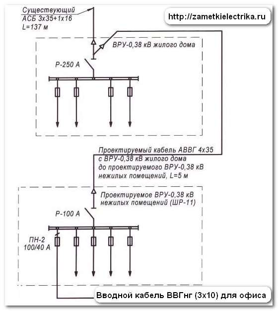
The office is on the first floor. The power supply of the office is carried out from the ASP-0,38 (kV) of the residential building through non-residential premises installed by a number of ASP-0,38 (kV) (SHR-11).
ШР-11 is a metal distribution cabinet of outdoor installation with dimensions of 500х1600х350 (mm). The manufacturer in this project was selected by IEK, but it is possible to replace the equipment with those of other manufacturers with the corresponding technical characteristics.
The projected VRU-0.38 (kV) of non-residential premises (SR-11) is installed in the basement and is powered by a cable of the mark АВВГ (4х35) from the cable terminals of the existing ASP-0,38 (kV) of the residential building. The length of this cable line is 5 (m).
Near the ASP-0.38 (kV) of non-residential premises (SR-11), a grounding device was installed in the form of a triangle.
As vertical earthing switches, steel round rods with a diameter of 16 (mm) of length 1 (m) are used. The connection of vertical earthing switches (vertices of a triangle) to each other is carried out by horizontal earthing switches made of steel strip 4х40 (mm) in length 1 (m).
The horizontal earthing switches are buried in the ground at 0.8 (m). All connections are welded, and the welds are treated with bitumen.

The measured resistance of the grounding device was 1.9 (Ohm), which satisfies the project conditions (no more than 10 Ohm). Measurement of the resistance I produced using.

The connection of the grounding device is made with an open steel strip 4x40 (mm) at a distance of 0.4 (m) from the floor level. The intersection of the steel strip with the partition is made in a steel pipe T50.
Thus, in the ASP-0.38 (kV) of non-residential premises it is fulfilled, i.е. a transition is made from TN-C to TN-C-S.
From the VRU-0.38 (kV) non-residential premises (SR-11) designed for the basement, the VVGng (3x10) introductory cable is laid to the VRU-0.22 (kV) office.
As you can see, the cross-section of the input cable is somewhat overestimated, because for 7 (kW) of power it was enough to apply a cable (3x4) or (3x6) - see. But apparently this was done with a view to further increasing the allocated capacity for the office.
The general plan of the supply network of the basement.

The length of the input cable VVGng (3x10) is 45 (m). It is laid in the cellar open in a PVC corrugated pipe at a mark of 2 (m) from the floor level. PVC corrugated board is fixed to walls and ceiling with the help of plastic clips or metal staples.

This method of attachment I like - it turns out fast enough, reliable and looks quite aesthetic. See for yourself, especially when several parallel cables are laid in a row.


In the basement there are many pipes of various communications and utilities.


In this regard, when laying the cable, the following requirements of the PUE (clauses 2.1.56 and 2.1.57) should be observed:


According to the PUE, p.2.1.58, the passage of the cable through walls, partitions and interfloor ceilings is carried out in a steel pipe T50 with a wall thickness of at least 3.2 (mm).


From the basement the input cable VVGng (3х10) through the interstorey overlap in the metal pipe rises to the 1st floor of the office to the VRU-0,22 (kV).

VRU-0,22 (kV) is installed in room number 7 (see the plan of premises) at the level of 2 (m) from the floor level.

There are 7 rooms in the office:
- vestibule
- cabinet number 1
- cabinet number 2
- cabinet number 3
- office number 4
- a bathroom
- corridor
The table below shows the areas and characteristics of these premises. As you can see, the vestibule and the bathroom belong to wet rooms, i.e. at which relative humidity of air makes more than 60%, but less than 75% (PUE, p.1.1.7.). Accordingly, special requirements will be made to the wiring in these premises, which I will discuss below.

Wiring diagram of input board in the office
As the input board selected SCHURN-1 / 12zo.
ЩУРн-1 / 12зо-0-36 УХЛ3 is a hinged registration and distribution metal shield for 12 modules with protection class IP31, with a lock and a window, designed for a single-phase counter

In this switchboard the following switching devices are installed:
- input single-pole circuit breaker BA47-29 1P 32 (A)
- single-phase (electronic one-tariff) active electricity meter of direct electric power connection SОЭ-5 / 60-1-110, 5-60 (А) with
- differential automatic device AD-12 2P 16 (A), 30 (mA) - 2 pcs.
- single-pole circuit breaker VA47-29 1P16 (A) - 2 pcs.
- single-pole circuit breaker VA47-29 1P 10 (A) - 2 pcs.
- zero bus N
- earth PE (ground)
Single-line circuit diagram of the input board (to enlarge the circuit, click on it):
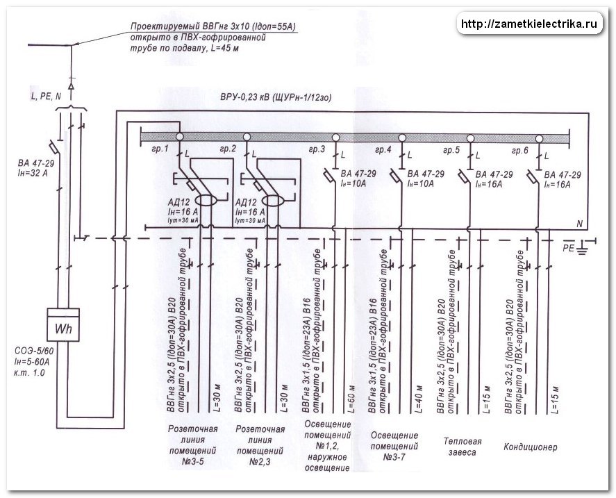
Phase L of the input cable VVGng (3x10) through the input single-pole automatic device BA47-29 with a rated current 32 (A) ESR-5 / 60-1-110 direct connection. It also connects the zero N. From the counter, the phase goes to the distribution (group) machines, and zero N - to the zero line N. The zero protective conductor PE is connected immediately to the PE ground bus.
The layout of the input shield consists of 6 group lines:
- rosette of premises No. 3-5 (room 1)
- rosette of premises No. 2, 3 (room 2)
- lighting facilities number 1, 2 and outdoor lighting (room 3)
- lighting of premises No. 3-7 (room 4)
- thermal curtain (gr.5)
- air conditioner (room 6)
The group wiring lines are made with three-core cables VVGng (3x1.5) and VVGng (3x2.5). Each group is protected by its automatic or automatic machine with certain characteristics, depending on the load capacity.
Here is the table with the calculation of the loads of consumers. Calculated loads are taken based on the equipment being designed.

The demand factor for power equipment is 0.8, and for lighting - 1. The average cosine of all consumers was cosφ = 0.87.
As a result, it turned out that the installed capacity of the office is 5 (kW). After taking into account the demand coefficients, the estimated capacity was 4.28 (kW). It is not difficult to calculate the total design current taking into account the averaged cosφ = 0.87. It turned out 22.38 (A). The cross-section of the input cable VVGng is 10 mm, ie, as I said at the beginning of the article, it is chosen with a good margin, because The long-lasting current of the supply cable is 55 (A).
I specially made a general table for the convenience of selecting wire and cable cross-sections. How to use this table I told in detail in.

As an apparatus for protecting the supply cable, an automatic circuit breaker BA47-29 with a rated current of 32 (A) with a characteristic C is installed. Even if the load in the office for any reason exceeds 32 (A), the lead-in cable does not overheat and will not leave building.
Such checks need to be carried out, for example. Each circuit-breaker has a "conventional non-switching current", i.e. for our example on the time-current characteristic C (I mentioned a reference to the article about BTX a little higher) at a current of 1.13 · In = 1.13 · 32 = 36.16 (A), the automaton will not shut down.
There is also such a thing as "conditional off current" of the machine, i.e. for our case at a current of 1.45 · In = 1.45 · 32 = 46.4 (A), the machine from the cold state will turn off in about 60 minutes (1 hour). The long-admissible current of the supply cable is 10 mm2 and is 55 (A), and the occurrence of such situations is not frightening for us.
And if the lead-in cable had a cross section of 10 square meters and 4 square meters (which is permissible for this project), then in the event of an overload of 47 (A), a current would pass through the cable within an hour, which to a large extent would exceed its long-allowed current (35 A) - the cable would begin to heat hot, melt, which could lead to a fire or short circuit, as a result, the input cable would in any case be out of order.
- 1,5 sq. M. - to install the machine for 10 (A)
- 2,5 sq. M. - to install the machine on 16 (A)
- 4 sq. M - to install the machine on 20 (A) or 25 (A)
- 6 sq. M - install the machine 25 (A)
- 10 sq. M - to install the machine on 32 (A) or 40 (A)
I hope that explained is available.
Consider the calculation of the power and current of the supply line to the air conditioner. The rated power of the air conditioner is 0.8 (kW), and the design current with cosφ = 0.87 is about 4.18 (A). The cross-section of the cable for powering the air conditioner is BBGng (3х2.5), i.е. with a good margin. The long-allowed current of the cable (3x2.5) is 25 (A), by the way, in the project even a little more - 30 (A) is indicated. As a protection device is installed automatic circuit breaker BA47-29 with a rated current of 16 (A).
If there is a power supply project, you will get all the necessary materials for installation work without any problems. I will give you some more useful materials on the topic of choosing and purchasing electrical products:
Installation of a potential equalization system
I would like to say a few words about how the system of equalizing the potentials in the office has been implemented.
According to the PUE, p.7.1.87, in the course of electric power transmission, an additional system of potential equalization (DCS) must be installed to provide additional electrical safety. Especially it concerns rooms with increased danger, i.e. in our case it is a bathroom.

In the bathroom is installed a steel extension box for equalization of potentials (PFC) U-994 with a terminal strip. This terminal block is connected to the PE rail of the input board by means of a copper wire with a cross-section of 6 square meters. And then the following metal structures are grounded:
- car wash
- cold water pipes (HVS)
- hot water pipes (DHW)

More details about the implementation of the system of equipotential bonding you can get acquainted.
Wiring Wiring Diagrams
The wiring diagrams in the project are divided into two drawings. The first figure shows the wiring diagram of the wiring of the power section, and on the second - only the lighting circuit.
The wiring diagram shows:
- ways of laying all cable lines
- place of installation of all junction boxes
- place of installation of all outlets and switches
- place of installation of lamps and other electrical equipment (air conditioning, heat curtain)
I hope that you know everything that is allowed in junction boxes.
The connection of the conductors of the wires of the power (power) lines I personally carry out, and the lighting lines - with the help of. I try to avoid soldering.
Wiring diagram of the power wiring of the office:

The cables to the outlets, air conditioner and heat curtain are laid in PVC - corrugated pipes with a diameter of 20 (mm) behind the suspended ceiling and behind the sheets of plasterboard. The passage of cables through walls and partitions is carried out in a steel pipe T25.
In this project, the power supply of the office is provided by double rosettes RA16-756 from Wessen (16A with grounding contact, for concealed installation, protection class IP20). They are installed at around 0.8 (m) from the floor level.
For information: in 2008, WESSEN became part of Schneider Electric.
In total, the office has 8 double sockets:
- 2 sockets in the office number 1 (room 2)
- 3 sockets in the office number 2 (two sockets with a gr. 2, and the third one with a room 1)
- 1 outlet in the office number 3 (room 1)
- 2 sockets in the office number 4 (room 1)
All the outlets of the office are powered by VVGng cable (3x2.5) through differential automata AD12 16 (A), 30 (mA).
In the vestibule, corridor and bathroom sockets are not installed.
The thermal curtain is installed at the entrance to the office and is supplied with a VVGng (3x2.5) cable from the circuit breaker BA47-29 1P16 (A) - gr.5. The air conditioner is installed between the cabinets No. 2 and No. 3 and is powered by VVGng (3 × 2.5) cable from the circuit breaker BA47-29 1P16 (A) - gr.6.
Lighting network wiring diagram:

Lighting networks are made with VVGng cable (3x1.5) and are protected by automatic devices BA47-29 1P10 (A) - gr.3 and gr.4. Cables for luminaires and switches are laid in PVC - corrugated pipes with a diameter of 16 (mm) behind the suspended ceiling and behind the sheets of plasterboard. The passage of cables through walls and partitions is carried out in a steel pipe T25.
All switches are installed at 1.6 (m) from the floor level.
The choice and arrangement of luminaires meets the requirements of SanPin 2.2.1 / 2.1.1.1278 - 03.
There are 6 ARS / R 418 4х18 (W) ceiling recessed luminaires installed in Cabinet No. 1 with the manufacturer "Light Technologies" (d = 26 mm, G13, protection class IP20).

The inclusion of these lamps is carried out by a three-button switch VS0516-351-18 from Wessen (16A with indicator, for concealed installation, protection class IP20). Each key switches on 2 lights in a row.
The same lighting fixtures are installed in offices No. 2, No. 3 and No. 4 in the amount of 2 pieces in each cabinet. Office lighting in the office number 2 and number 3 is carried out by a two-button switch C56-039 from Wessen (6A with indicator, for concealed installation, protection class IP20).
Switching on the fixtures in Cabinet No. 4 is carried out by a single-key switch C16-053 from Wessen (6A with indicator, for concealed installation, protection class IP20).
In the bathroom there is one ceiling light DR / PRS 418 4х18 (W) with fluorescent tube lamps from the manufacturer "Light technology" (d = 26 mm, G13, protection class IP43). This lamp meets the requirements of.
In the corridor there is a recessed luminaire RG 100 with an incandescent lamp of 100 (W) from the manufacturer "Light technology" (socle E27, protection class IP54).

Light control in the bathroom and the corridor is carried out using a two-key switch C56-039 from Wessen (6A with indicator, for concealed installation, protection class IP20).
The wall-ceiling lamp PSH-60 with incandescent lamp 60 (W) (E27 base, protection class IP54) is installed in the tambour, which is controlled directly from the vestibule by means of a single-key switch LEX411604 from ELSO.

For outdoor lighting at the entrance to the office, a PSH-60 luminaire with an incandescent lamp of 60 (W) (E27 base, protection class IP54) is installed, which is controlled from the vestibule by means of a single-key switch LEX411604 from ELSO.
In total, the office has 15 podzroetnikov and 11 distribution (branch) boxes at 192.
P.S. In this article I gave you an example of a typical project for the power supply of an office located in an apartment building. As I said at the beginning of the article, you can take this project as a basis for a wiring project in an apartment or a private house, changing it to your own needs.Thank you for attention.