Antipyretics for children are prescribed by a pediatrician. But there are situations of emergency care for fever, when the child needs to give the medicine immediately. Then the parents take responsibility and apply antipyretic drugs. What is allowed to give to infants? How can you bring down the temperature in older children? Which medications are the safest?
A set of developed wires and cables, connected one to another in some way and if necessary equipped with electrical installation elements (terminals, connectors, etc.), is called a tourniquet.By their design, bundles are divided into intra-block and interblock.
In-block wiring harnessesserve for electrical connection of individual units, blocks and electrical parts inside the device, and inter-unitthey are used for electrical connection of various CEA and devices to one system.
The design of the in-block bundling is determined by the type of the device body, the requirements for their maintenance and repair. Depending on the arrangement of the nodes in the housing, such bundles can be: flat fixed with detachable connections; flat movable with integral connections; three-dimensional movable; volumetric with movable taps. All-in-one connections for in-unit installation are mainly used in CEA, intended for harsh operating conditions.
The typical technological process of manufacturing a bundle consists of cutting wires and insulating pipes, laying wires on a template, bundling them in a tourniquet, working out the ends of the wires of the bundle and marking them, controlling the manufactured rope (wire), protecting the bundle with an insulating tape and its final control (visual inspection at compliance with the standard and continuity).
Template for layout of harnessesis a rectangular plate made of plastic or plywood, on the surface of which a full-scale bundle is plotted and end and angled pins are fixed (Fig. 4.8).
Laying of the wire starts, fixing it on the angled stud. Then the wire is laid according to the scheme of the bundle, bending it on the angled studs and fastening it to the end pin. The starting and ending studs have the same number. When all the wires are on the template, they are tied with a linen thread.
In the bundles, where it is impossible to replace the damaged wires, spare wires are provided, the number of which is 8-10% of the total number of wires in the bundle, but not less than two. The length and cross-section of the spare wires should be equal to the largest length and section of the wires in the harness. The length of the harness taps should be sufficient to connect to the nodes and components of the device circuit without tension; In addition, you should have some margin of length (10-12 mm) for re-stripping and soldering each end of the wire.
When designing the harnesses, the following requirements must be met:
two or more parallel insulated wires going in the same direction and a length of more than 80 mm must be connected in a bundle;
longer wires need to be laid in the top part of the harness so that the branch of the bundle leaves from under them. Wires of small cross-sections (0.2 mm 2) should be laid in the central part of the bundle;
depending on the operating conditions, as well as on the insulation of the wires entering the bundle, it is necessary to make knitting with threads, braids or bands of synthetic materials or to make winding with electrical insulating tapes or films. It is also possible to use electrically insulating tubes instead of winding the tape or perform mechanical and automatic binding of the tows with threads with tension, in which the insulation of the wires is not disturbed;
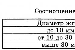
the step of knitting the loop loops depends on the diameter of the tow and is selected from Table 4.3.

in the areas of the stripping of the tourniquet (before and after it), bandages of 2-3 loops placed side by side should be made. At the beginning and end of the binding there must also be bandages, which consist of two to five loops and have terminal nodes. A loop must be made before each wire leaving the harness. An example of knitting and laying with a bandage is shown in Fig. 4.9;
depending on the number of wires and the diameter of the bundles, the binding should be carried out in one, two or more strings. Threads prior to the beginning of mating are recommended to be rubbed or soaked with ceresin. Knots of linen threads after knitting need to be covered with glue (for example, BF-4) or varnish; The ends from kapron threads after mating should be melt.
After knitting the wires into the harness, they are fixed for their ends. All the ends of the wires are marked in accordance with the wiring diagram.

Marking of wires, cable products and harnessesduring wiring should provide the ability to test electrical circuits, finding malfunctions and repairing equipment. For marking, the following methods are used: inserting in a wiring harness having different colors; coloring or numbering of PVC pipes used for clamping the ends of insulation (the tubes are marked on the machine or the numbers are handwritten with ink marks);
putting on the wires of plastic tags with the symbols of the connection points;
marking the insulation with a colored printing foil (for cables with PVC and polyethylene insulation and RK type cables);
use of a metal tag (mainly on RK type cables);
use of a sticky marking tape (a bandage of 1.5 ... 3 turns per wire or cable).
Marking is applied to both ends of the wire, cable or bundle at the points where they are connected. The designation of wires, cables and harnesses on marking tags, tapes and tubes or directly on wires must correspond to the mark shown in the technical documentation. If the tag on the wire or cable is not glued, it is tied on the wire (cable) with a knot or loop.
To mark wires with a diameter of up to 1 mm in diameter, color marking tubes with an internal diameter corresponding to the diameter of the wire should be used.
The marking of the wires in the harness is made with tags or tapes made of polymer materials. The length of the tags or the width of the ribbons should be no more than 12 mm.
Then they control the wiring harness by means of a dial, for which they connect the harness with the same numbers to the ends of the wires in series with the device (indicator).
Control of complex bundles is carried out on special semi-automatic stands according to a given program. All information about such control is recorded in the computer.
Fastening of bundles, wires and cables to the body of the CEA or its elements is done with the help of: staples, tapes, clamps, adhesives, mastics, compounds, threads, ribbons, plastic self-adhesive tapes.
Staples, bands and clamps must correspond to the shape of the bundle and, when fastened, do not allow its displacement.
In order not to damage the insulation of the wires when fastening with metal brackets and clamps, under them it is necessary to put elastic gaskets of insulating material protruding beyond the edge of the clamps (clamps) by at least 1 mm.
The distance between the staples or clamps when attaching them to linear sections must be selected depending on the diameter of the bundle (wire or cable) in the range from 100 to 300 mm. Identical wires having a cross section of less than 0.35 mm 2 shall be fastened with a distance of no more than 80 mm between attachment points.
When glue or mastic is used to fix wires, ropes and cables, the distance between the gluing points should be chosen depending on the diameter of the wire (cable or cable) according to Table 4.4

The plaits, with a diameter of more than 15 mm when bonded, are fixed with threads through the hole in the chassis.
Passage of the tow, wire or cable through the hole in the metal chassis must be carried out through the insulating sleeve, which is installed in the hole.
When moving wires, bundles and cables from the fixed part of the device to a movable part (for example, from the case to a board or panel, etc.), they should be placed in such a way that the wires are twisted and not bent when removing the moving part. At the same moving parts of the bundle do not need to tie and leave the necessary margin along the length.
Soldering and tinning: purpose, application and physicochemical basis. Solder, fluxes of their brand and application. The technology of soldering with soft and solid solders, temperature regimes, heat removal. Group methods of soldering. Equipment and tools: purpose, design and methods of work. Ways of soldering wires of different brands and cross sections. Ultrasonic brazing. Laser soldering. Solder connection requirements, quality control. Purpose and application of tinning, quality control. Automation of soldering and tinning processes
Soldering- physicochemical process of obtaining a compound as a result of the interaction of a solid and a liquid metal (solder). The resulting layers on the boundaries of the seam and the surfaces of the parts to be joined are called junctions. To obtain junctions, it is necessary to remove oxide films from the surfaces to be joined and to create conditions for the interaction of solid and liquid metals. When the more solderable solder that has entered into interaction with the material is crystallized, a solder joint is obtained.
One of the advantages of soldering is the possibility of combining into a single unit a plurality of elements constituting the article. Soldering, like no other method of connection, meets the conditions of mass production. It allows you to connect dissimilar metals, as well as metals with. glass, ceramics, graphite and other non-metallic materials.
Tinning - the process of coating the soldering of electrical installation elements (terminals ERE, contact pads of printed circuit boards, metallized holes, conductors of wires and cables, etc.). It is necessary to improve the solderability of the connected surfaces of the elements during their installation.
To perform a quality solder connection, you need:
7. Prepare the surfaces of the parts to be brazed;
8. activate the solder metals and solder;
9. Ensure interaction at the boundary "basic metal-liquid solder;
10. create conditions for the crystallization of the liquid metal interlayer of the solder.
Surface preparation involves the removal of contaminants and oxide films from it, which interfere with wetting by its molten solder. The films are removed by mechanical or chemical means. With mechanical cleaning
a thin surface layer of the metal is removed with the help of sandpaper, wire brush, etc. To improve productivity when processing large surfaces (for example, printed circuit boards), hydroabrasive treatment or cleaning with rotating brushes made of synthetic material into which abrasive particles are introduced is used. Surface roughness after mechanical cleaning promotes spreading of flux and solder, as small scratches on the surface are the smallest capillaries.
Chemical treatment (degreasing) of the product surface is carried out in solutions of alkalis or organic solvents (acetone, gasoline, alcohol, carbon tetrachloride, freon, alcohol-benzine and alcohol-fluoric mixtures) by rubbing, lowering into a bath, etc.
Purified parts must immediately be sent for tinning and soldering, as the storage time for copper is 3-5 days, for silver - 10-15 days.
The activation of the metals to be joined and the solder occurs with the help of various fluxes, the creation of a special gas medium or physical and mechanical action (mechanical vibrations, ultrasonic vibrations, etc.). Activation is necessary, since during the heating of metals and the melting of solder, the interaction of their surface layers with oxygen of the air occurs, which leads to the appearance of a new oxide film.
Soldering with fluxes is most common. The molten flux spreads over the soldered surface and solder, wets them and interacts with them, as a result of which the oxide film is removed. But the use of fluxes can lead to the fact that their residues after soldering, as well as the products of their interaction with oxide films, create slag inclusions in the brazed seam. This reduces the strength of the joint and leads to its corrosion. To avoid this, the flux residues after rinsing are washed off (wiped) usually with organic solvents.
To ensure interaction at the interface of the "base metal-liquid solder", it is necessary to achieve a good wetting of the surface of the base metal by the molten solder (ERE outlet, petals, wire, etc.). The strength, corrosion resistance and other properties of solder joints. The process of wetting and spreading the solder is influenced by certain technological factors (the way of removing the oxide film, the flux used, the soldering regime, etc.).
Crystallization of a liquid metal layer occurs after removal of a source of thermal energy. The crystallization process has a significant effect on the quality of soldered joints.
Solder and fluxes for solderingare intended for performance of technological processes of hot tinning and soldering of non-ferrous and ferrous metals and metallized metal and nonmetallic materials. They are divided into:
solders for low-temperature brazing with a melting point of less than 450 ° C;
solder for a high-temperature folder with a melting point above 450 ° C.
The symbol of the solder marks consists of the letters "P" or "Pr" and the following abbreviated names of the main components: tin-O, lead-C, antimony-Su, bismuth-V cadmium or cobalt-K, silver-C, copper-M , indium-In, zinc-C, nickel-H, gallium-Gl, germanium-G, titanium-T, gold-Z, manganese-Mc, boron-B, phosphate-F, brass or lithium-L, iron-F , aluminum - A. The content of the main component as a percentage of the mass is further indicated. The letter "P", which stands at the end of the mark through a hyphen, means that the solder has an increased purity.
The main grades of solders and their melting point (Tm) are shown in Table 4.5.

Fluxesare intended for use in the technological processes of soldering and hot tinning with the purpose of removing the oxide film from solderable surfaces and solder, protecting the surface of metals and solder from oxidation during soldering, and also reducing the surface tension of molten solder at the metal-solder flux interface
The conventional designation of flux grades consists of the letter "F" (flux) and the abbreviated name of the constituent components: K - rosin, Cn - alcohol, T - triethanolamine, Et - ethyl acetate, C - salicylic acid, B - benzoic acid, Bf - boron fluoride cadmium (or zinc), P - polyester resin, D - diethyl amine, Cc - semicarbose, Gl - glycerol, Fs - orthophosphoric acid, C - zinc chloride, A - ammonium chloride, B - water, L - laprol, Kp - catapin, M - maleic acid.
Fluxes are low-temperature (use temperature less than 450 ° C) and high-temperature (with a use temperature of over 450 ° C). Depending on the corrosive effect on the metal being soldered, they are divided into the following groups: non-corrosive inactive, noncorrosive weakly active, slightly corrosive active, corrosive active, corrosive highly active.
To avoid corrosion of the mounting joint, the residues of corrosive and even slightly corrosive fluxes must be removed immediately after soldering. Remove the fluxes with liquids in which they dissolve. For some flux grades, it can be organic solvents, for others - water.
The most common flux grades are given in Table 4.6.


In addition to fluxes, protective liquids (for example, ЖЗ-1, ЖЗ-2, ТП-22) are used to protect the mirror of molten low-temperature solder from oxidation in tinning and soldering baths. They are a mixture of petroleum oils with organic components.
The quality of solders and solder fluxes is determined by technological characteristics: spreading coefficient (Kp) and wetting time (t CM). The coefficient Kp = S p / Sq, where S p is the area occupied by the solder; Sq - the area of the unmelted solder in the initial state; t CM - the time during which tinning of the mounting element takes place (should not be more than 3 s).
The technology of soldering with soft and solid solders, temperature regimes, heat removal.The technological process of soldering consists of the following operations:
preparation of the surfaces of the connected elements for soldering; fixation of the connected elements is tightly one to the other; application of a dosed amount of flux and solder; heating of parts to the set temperature and holding for a certain time; *
cooling of the joint without shifting the parts included in it;
cleaning the connection; quality control of soldering.
Soft (low-temperature) solders (see Table 4.5) are used for electrical installation of equipment. Therefore, the temperature regimes of their use depend on the permissible temperature for those elements that take part in the installation. Soldering can be carried out by soldering iron or in baths with molten solder. When tinning and soldering with molten solder, the required bath temperature increases for each brand of solder by formula
tn = tin + (45 ... 80) ° C,
where t n - temperature of solder, t HK - temperature of the beginning of crystallization (first digit Mp in Table 4.5). The magnitude of the excess (45 ... 80) ° C over t HK depends on the mass of the product to be soldered, the time of immersion, the flux to be used, and the restrictions on thermal effects in accordance with the specifications for the ERE.
To avoid overheating of soldered ERE, use a heat sink, which for the time of soldering is fixed on the ERE terminals.
There are other methods of heat removal for individual and group soldering of circuit boards. Mounting plate 2 (Fig.4.10, a) is installed in the device 5, made by injection molding in the form of a heat block. In the case there are built-in springs 6, which are pressed by springs 6, carrying the supporting copper sockets 4, which have slots for the leads. The mounting plate 2 is installed on these heat-sink racks so that the terminals of the radio elements fit into the slots of the sockets. The board is fixed in the device by turning the pressure plate 1. Thus, during the individual soldering, the heat sink is carried out by the entire body of the device.
When group soldering the hanging elements on the circuit board, the heat sink method is used, carried out with the help of a fraction of aluminum wire with a diameter of 3 mm (Fig. 4.10, b). Fraction 3 is poured into the cage 1, where the mounting plate 2 is inserted before the group soldering by immersion or hydrostatic method. At the end of the soldering, the shot is poured out.
Solid (high-temperature) solders are used for structural soldering of mechanical connections in the manufacture of large parts (for example, chassis, hulls, etc.). High-temperature soldering of mechanical connections is performed in the fields of high frequency currents (HF), in furnaces or baths with molten salt.

Induction brazing (HD).A technological device for induction soldering or soldering by high frequency currents (HF) is an inductor, which is a coil made of highly conductive tubular material through which the coolant is pumped. As the equipment for soldering the generator HDTV serves. Usually induction brazing is used to connect elements operating at microwave frequencies, for example, microwave waveguides. The quality of the connection is enhanced by the soldering process in a vacuum or protective gas environment (hydrogen, nitrogen or a mixture thereof). A major disadvantage of HDTV soldering is the need for special devices for each assembly unit.
Soldering in furnaceswith a controlled atmosphere ensures the uniformity of heating. Heating of the soldered materials is carried out in an active gas environment. In this case, fluxing can be avoided.
Soldering in bathtubswith molten salt is used to assemble large-sized products. The composition of the melt is selected in such a way that it provides the desired temperature and has a fluxing effect on the surfaces to be joined. The assembled parts for soldering (the gap between the parts to be brazed must be in the range 0.05 ... 0.1 mm) is subjected to preheating in the furnace to temperatures of 80 ... 100 ° C below the melting point of the solder. This is necessary to avoid warpage of parts, as well as to maintain the temperature in the bath. After holding in the melt for 0.5 ... 3 minutes, the part together with the device is taken out of the bath and cooled, and then thoroughly washed with water to remove residual flux.
Group methods of soldering.The methods of group soldering in the production of REA are classified according to the sources of thermal energy, which is the main factor in the formation of soldered joints (Fig. 4.11). Soldering of elements with pin pins, which are placed on printed circuit boards, under the conditions of in-line production is carried out by two methods: immersion and a wave of solder.

Different versions of the group methods of the folder are shown in Fig. 4.12. The printed circuit board, when soldered for 2 ... 4 s, is immersed in molten solder to a depth (0.4 ... 0.6) h, Where h - The thickness of the board. As a result of the capillary effect, the mounting holes are filled with solder (Fig. 4.12, a). Simultaneous influence of temperature on the entire surface of the board leads to its overheating and can cause increased warpage. To reduce the area of action of the solder, a special mask (of paper or fiberglass) is glued onto the board from the mounting side, in which holes for pads are provided. The residues of solvent flux, which fell into the solder, evaporate intensely, which leads to local impurities. To reduce the amount of non-solder, use soldering with a slope of the board (angle 5 ... 7 °) (Fig. 4.12, b) or apply to the board mechanical oscillations with a frequency of 50 ... 200 Hz and an amplitude of 0.5 ... 1 mm (Fig. 4.12, d, e). Good results can be obtained by pulling the board over the mirror of the solder (Fig. 4.12, at). In this case, the board is installed on the device at an angle of 5 °, immersed in the solder and stretched along its surface. With this method, suitable conditions arise for the removal of oxidation products.
Selective soldering(Fig. 4.12, (e) provides a selective supply of solder to the parts to be soldered through special nozzles made of stainless steel. Between the board and the filters there is a layer of heat-resistant rubber. With selective soldering, the temperature of the board and the heating of the ERE are reduced, the consumption of solder decreases, but the cost of manufacturing special spinnerets can be considerable.
Soldering with a wave of solderis the most common method of group soldering. In this case, the board directly moves linearly through the wave of solder wave. Its advantages are high productivity and a short time of interaction of the solder with the board, which reduces the overheating of the ERE and the distortion of the dielectric. A variation of the soldering wave is cascade soldering (Fig. 4.12, g), in which several waves are used.
High quality soldering provides a way of plunging the board into the bath, in which there is a grid with cells 0.2x0.2 mm, for example, from nickel (Fig. 4.12, h). When the board touches the grid, the solder is forced through the cells and under the action of the capillary effect it enters the gap between the terminals and the metallized holes. When moving back, excess solder is tightened by the capillaries of the mesh, which prevents the appearance of "icicles"

Equipment and tools: purpose, design and methods of work.Depending on the type of production, soldering is carried out individually with a heated soldering iron or with various group methods.
Soldering with soldering ironit is used for electrical installation under conditions of single or small-scale production.
The design of the electric soldering iron is shown in Fig.4.13. The necessary temperature regime for individual soldering is provided by the thermophysical characteristics of the soldering iron used: the temperature of the working tip of the tip (tip 1 on, Fig. 4.13), the stability of this temperature, which is maintained by means of a thermocouple 4, the power of the heating element 14.

The temperature of the tip of the tip is set at 30 ... 100 ° С above the melting point of the solder, because during soldering, the temperature of the soldering iron tip is lowered due to thermal costs when heating the soldered parts. Recommended capacity of soldering irons for soldering chips 4 ... 18 W, for printed mounting 25 ... 60 W, for soldering wires (bundles) 50 ... 100 W.
For tips of soldering irons, copper is used, which is covered with a layer of nickel to increase its wear resistance. The sequence of the soldering process:flux the elements of the mounting joint with a brush moistened in a liquid flux; heat the elements of the mounting joint, touching them with a soldering tip; insert the stick of solder into the soldering zone; they can withstand heating until the solder spreads out and fill all the gaps between the surfaces being joined.
After finishing the soldering to the details, you can not touch the full hardening, solder. The total soldering time of a single assembly joint with a soldering iron is 1 ... 3 s and can not be more than 5 s.
If soldering and tinning is done manually, it is necessary to ensure the removal of heat from the ERE, semiconductor devices, ICs, etc., which are sensitive to its effects (according to specifications for these elements). Heat sinks in the form of clamps are fixed on the terminals of the soldered elements between the solder points and the body of the element. After soldering, the heat sinks are removed not earlier than after 5 seconds. For reuse, the heat sinks are changed or cooled.

Electroplating installation diagramis shown in Fig.4.14. The board 3 with the terminals pre-coated with a flux is installed on the die 5. Each soldering site has its own spinneret, the opening of which must coincide with this location. In this position, the board is fixed with a clamp 4. The molten solder 1 is in a volume closed on all sides and its temperature is maintained by the molten salt bath environment 8 heated by the electric heating elements 9. Through the bronze diaphragm 7 the vibrator 6 communicates the molten solder with a frequency of 100 Hz, which improves the quality of soldering. The solder is fed through the spinnerets to the soldering points by lowering the piston 2.
Wave Soldering Wiring Diagramis shown in Fig.4.15. In a bath with molten solder, the temperature of which is maintained by a salt bath 2 with heating elements 1, a branch pipe with a paddle pump 4 driven by an electric motor by means of a shaft 3 is installed. The height of the wave depends on the speed of the electric motor and is controlled by its variation.

Cascade solderingdiffers from the wave by the presence of several waves (Fig.4.16) created by the thresholds 3 on the inclined surface of the base 5. The molten solder 8 by the pump 7 through the slit 4 arrives at these thresholds at a constant speed and flows downward. From the flow in other directions, the solder protects the side walls 1. As in the previous schemes, the temperature of the solder is maintained by a salt bath 9 with electric heaters 6.
These types of soldering are most suitable for large-scale and mass production of boards with one-sided arrangement of hinged elements. They ensure continuous movement of the boards during soldering and local heating.

Ways of soldering wires of different brands and cross sections.After the treatment, as described above, the mounting copper wires and cores of cables that are not coated must be handled. Separate cores of wires after removal of insulation before servicing must be twisted. When tufting wires and cables, the flux is recommended to be applied at a distance of 0.3 to 2 mm from the insulation. Non-protruded sections of the core are allowed between insulation and the tin-plated part of the wire to 1 mm. The cross sections of the conductors must correspond to the load current. The total cross-sectional area of the wires and leads of the ERE, connected to the contact, should not exceed the smallest contact area of the contact.
When soldering wires and veins of cables it is necessary to fulfill the following requirements: the wiring of each other must be performed with the help of electrical contacts. The options for fixing the cores of wires and terminals of ERE on the contacts of different structures are shown in Fig. 4.17:
in each soldered contact hole it is allowed to solder not more than three wires. In this case, each wire must be mounted in the hole itself, without twisting it with other wires and ERE terminals. If the mounting hole is small for soldering, it is necessary to use the electrical installation contacts; to the clamping contacts, the wire must be fixed only with the help of cable lugs (for a single clamping contact no more than two wires). Clamping contacts must be stuck with paint or varnish;
wires of small cross sections (less than 0.2 mm 2) should be installed carefully; Wiring must be done only once, so as not to break them;
the drive stock in the form of a hinge is put on the board, but there should be no wiring of the wire beyond its edge; wire to the place of soldering must be brought from below; the connection of the installation wires to the contacts must be carried out in such a way that the length of the bare part of the conductor wire from its insulation to the soldering station is no more than 2 and not less than 0.5 mm (after soldering). When the distance between the contacts is less than 5 mm, the bare wire should not exceed 1.5 mm.

The connection of the mounting wires to the terminals of the screw terminals is carried out in various ways. In one of them, rings made of stripped and irradiated cores of wire diameter larger than the diameter of the screw (Fig. 4.18, a). In another method, cable lugs with screw holes are attached to the wires of the wires by soldering, welding or crimping (Fig. 4.18, b).
Placement of wires in the cable lug is carried out in the following sequence: an electric insulating tube with an internal diameter equal to the outer diameter of the wire is put on the wire; The wire vein after cutting and tinning is inserted into the tip; The tip of the tip is squeezed and soldered to the core of the wire from the inside to the legs; Crimped the following tabs on the insulation of the wire; on top of the tip put on an insulating tube
(Fig.4.18, b).

Ultrasonic brazing.Ultrasonic vibrations introduced into the solder destroy the oxide films on the surface of the metal, improve its wetting with liquid solder, the flow of solder into the capillary depressions, promote the degassing of the melt, which improves the quality of the soldered joint.
Cavitation resulting from the action of ultrasound in the solder contributes to the destruction of oxide films, and acoustic currents carry away particles of oxides and contaminants, remove metal on the sharp edges of the contact. Oglyaschiesya areas of metal are easily wetted with solder.
Laser soldering.Laser radiation differs from other sources of electromagnetic energy in a very narrow direction. Concentrated heating with focused beam energy has several advantages, the main ones of which are: contactless energy supply to products by removing the source from the heating object; the possibility of transferring energy through optically transparent shells both in a controlled environment and in a vacuum; heating of different materials regardless of their electrical, magnetic, etc. properties in a wide range of regulation and control of soldering parameters. Depending on the design features and mass of the products to be soldered, as well as the properties of the materials to be connected, different equipment of different power is used.
Solder connection requirements, quality control.TO
solder joints are subject to the following requirements:
when fluxing, the flux should not be allowed to enter the ERE and the contact parts of the electrical connection;
the shape of the brazed joints must be a frame joint with concave fillet welds (Fig. 4.19) and without excess solder. It should allow visually to see through the thin layers of solder the contours of the individual wiring elements entering into the connection;
the surface of the solder jaws along the entire perimeter of the soldered joint must be concave, continuous, smooth, glossy or light matte, with no dark spots and side inclusions.

The quality of soldering is checked by external inspection, and when necessary - using a magnifying glass. Well-executed soldering should be considered one on which the contours of the parts to be connected are clearly visible, but all the holes are filled with solder. Soldering should have a glossy surface, without sags, cracks, sharp slopes. Possible types of solder joint defects are shown in Fig.4.20.

The mechanical strength of soldering is verified by tweezers with PVC tubes on its ends (when this is indicated in the TD). The tension force along the wire axis should be no more than 10 N. It is forbidden to bend the wire near the place of soldering. After monitoring and acceptance, the place of soldering is painted with a transparent colored lacquer.
Purpose and use of tinning, automation of soldering and tinning processes.The high demands placed on fixed joints of parts and elements in wiring carried out by the soldering method make it necessary to carry out the operation of hot tinning.
Usually hot tinning of wiring elements is carried out only if they are unsatisfactory solderability (the need to control solderability is laid in the TD). When tinning, the following requirements must be met:
tinning of electrical installation elements (ERE terminals, contact pads of printed circuit boards, metallized holes, conductor wiring, etc.) should be carried out basically with the same solders as the subsequent soldering. Sensitive to the temperature of ERE are soldered with solders with reduced melting point. Just as in the case of soldering, when tilling such ERE it is necessary to use heat sinks;
the application of flux to the surfaces to be irradiated during manual tinning should be carried out for the minimum time that is necessary to ensure wetting of the surface with solder. With mechanized tinning, the entire surface touches the solder;
when tinning, the distance along the length of the ERE output from the mirror of the solder to the ERE casing should be not less than 1 mm (or in accordance with the specification for ERE);
when tinning the terminals of the ERE manually by immersion in solder or by soldering irons, the duration of the process should not exceed the time specified in the specification for ERE. When there is no such restriction, the duration of tinning is taken no more than 5 seconds.
TO Category:
Manufacture of radio equipment
Harnessing of mounting wires, cables and harnesses
The preparation of the mounting wires begins with the straightening (alignment) of the wire coming to the plant in the bays. After that, the wire is cut into pieces of the required length (specified in the technical documentation).
During installation work, splicing of wires from individual sections is not permitted. The wire mark, its cross-section and coloring are also determined by technical documentation.
The method of preparing the mounting wires depends mainly on the scale of production. In individual production, wire is cut with scissors or cutters on a scale scale. In serial production, various devices and machines are widely used for measuring wire cutting, which greatly increase labor productivity and the accuracy of this operation.
In Fig. 1 shows scissors for measuring wire cutting, characterized by high productivity with a cutting accuracy of +0.5 mm. Scissors have a movable and fixed disc with holes of various diameters, an emphasis and a handle. With the inoperative position of the scissors, the holes in the discs, due to the presence of a lock and a tension spring, coincide. Cutting a batch of workpieces is preceded by setting the stop by using the arrow to the required length; readings are made on a ruler with divisions. Then select the required hole on the disk by the diameter of the wire, pass the wire into it until it stops; By pressing the handle, rigidly connected to the movable disk, the workpieces are cut.

Fig. 1. Scissors for dimensional wire cutting: 1 - movable disk, 2 - fixed disk. 3 - stop, 4 - ruler, 5-arrow, 6 - handle, 7 - retainer, 8 - spring
Cutting and stripping of the ends of the mounting wires in mass production are performed on a special automatic machine (Figure 2). The performance of this machine is 5500 wires per hour.
After cutting, the mounting wires and cables are fed to the termination of the ends, which consists of the following operations:
- stripping of the ends from insulation and shielding braiding, removal of oxide film, twisting of veins, tinning and fixing of the ends of insulation.
The method of sealing ends depends on a number of factors:
- the brand of the wire or cable used, the design features of the installation and its components, the operating conditions of the radio equipment, and also the scale of production.
Stripping of the wire from the insulation should be carried out at a length that would ensure the reliability of the fastening of the veins on the contact lobes without unnecessary technological waste. Practice shows that for most connections it is sufficient to clean the insulation on a section of wire 7-10 mm long. It is not possible to clean the insulation with a knife, since it is possible to cut the current-conducting conductor of the wire.
The insulation of the wire to some extent determines the method of stripping.
Textile, plasgikatovuyu and film insulation is removed from the wires in one of the following ways:
- with wires MGV, MGVL, MGVSL, BPT-250, TM-250, PMV, PMOV (with internal insulation from fiberglass), BPVL, MCSL - by the notch method on the machine:
- with the wires MGV, MGVL, BPVL, PVL, PMV, PMOV (with internal isolation from cotton fiber), PMVG, MGSHV, MGF, MOG - by the method of electric burning at the machine simultaneously with measured cutting of blanks or on a special device installed on the table of the installer and controlled by two foot pedals located under the table.

Fig. 3. Machine for cutting and stripping the ends of the mounting wires

Fig. 4. Stripping the insulation from the end of the wire: 1 - insulation, 2-wire
The device has racks on which the columns 3 are arranged in parallel. On the right side, the right sponge 2 is fixed firmly on the columns, the left sponge 1 on the brass sleeves freely slides on the columns. To clamp the insulation at the time of its removal serves as a ribbed part of the sponges. Holders of wires with copper pins are attached to the sponge-l. To the pins power is supplied: the heaters from the constantan wire are fixed
screws. The holders of the cable are attached to the holders by means of which it is possible to move the movable sponge to the right or to the left, shifting or diluting the loop heaters to which the voltage of 3-4 V is supplied from the step-down transformer. The pedals serve to set the heaters to a position where a gap is formed between them, where the wire is introduced. By pressing the left pedal of the device, the heaters' loops are reduced thereby performing the firing of the insulation. Pincers and knives for electric insulation burning, which operate on the same principle as the described device, were widely used in factories. Isolation from single wires МГВ, МГВЛ, МГВСЛ, БПВЛ, БПТ-250, Г1ВЛ, Г1МВ, ПМОВ (with the internal isolation from fiber glass), МЦСЛ, ЛПЛ, МОГ, ТМ-250 are removed by special forceps.
Enamel insulation is removed:
- with PET wires, PEL - grinding skins, scraper and others;
- with the wire PEV and TEM - dipping the ends of the wire into formic acid followed by rubbing with a soft rag;
- with multicore wires LESHO and LESHD- heating in the upper part of the flame of the alcohol burner of the fluffed end of the wire to a light straw light and quickly immersing in alcohol with a strength of at least 94 °, followed by rubbing with a soft rag.

Fig. 5. The device for stripping insulation from mounting wires by firing: 1-movable sponge. 2 - an immobile sponge. 3 - column, 4 - rack

Fig. 6. Tongs for removing insulation from the ends of the mounting wires

Fig. 177. Tongs for removing insulation from the ends of the mounting wires: 1 - gon, 2 and r-knives, 4-handle, 6-clamp
In addition to the methods considered, heating and mechanical appliances are used to remove enamel insulation.
The heating device is a porcelain tube on which a heating coil is wound. The tube is fixed on a wooden handle. Power is provided through a step-down transformer. To remove insulation, the ends of the wires are introduced into the porcelain heated tube, the enamel is burned.

Fig. 8. Mechanical device for stripping wires with enamel insulation
Mechanical devices designed to remove enamel insulation include a device with metal brushes (Figure 8), which rotate by an electric motor in opposite directions. Using the setscrews, you can adjust the clearance between the brushes. To remove the insulation, the end of the wire through the hole in the protective cover is fed to the rotating brushes. The insulation is removed in a few seconds. A machine with rotating metal brushes can be used to remove any kind of insulation, including rubber and glass fiber.
For cleaning the ends of high-frequency cables, a semiautomatic device is used with the help of which step-by-step transitions remove the insulation with the end of the cable according to the specified dimensions depending on the cable design. The cutting of the ends of high-frequency cables is shown in Fig. 179. On the front panel of the machine there are nests, behind which there are spindles with heads, intended for cutting one of the layers of insulation. The semiautomatic motor simultaneously drives all the spindles.
The first socket and the corresponding head spindle are intended for the removal of chlorovinyl insulation, the second for removing the shielding braid, the third for removing cotton insulation (by firing), the fourth for cutting polyethylene insulation and the fifth for cutting rubber insulation. Thus, cables with PVC insulation are treated in jacks 1, 2 and 4, and from cotton - in jacks 3, 2 and 5. When processing cables, the integrity (no incisions) of the conductor core, internal insulation and shielding braiding must be ensured. Dimensions a, b, e, d (see figure 9) are determined by the type of connector and must correspond to the sketches of the technological map or drawing.
The oxide film on the bare part of the conductive layer is scraped with a scraper (Figure 10) or a medium grain grinding cloth. The stripped core is treated with POS-40 solder by 5-7 mm from the end.
The ends of the outer textile braiding of cables RK-44 and RK-45 are fixed with threads # 00, and after that they are covered with a string-rope. If it is necessary to round the ends of the shielding braid of the cables, they are immersed in a molten solder or irradiated with an electric soldering iron.
The ends of stranded mounting wires, for example MGV, BPVL, MGVL and others, are pre-twisted. For twisting, use the special tool shown in Fig. eleven.
The stripped end of the mounting wire is fed through the guide bush until it contacts the fast-rotating clamping spring element fixed to the motor shaft.

Fig. 9. Cutting the ends of high-frequency cables: a -cables RK, б-cables RK-44 (RK-45); 1-core, 2-insulation, 3-shielding braid, 4-plastic insulation, 5-cotton thread No. 00. 6 - braided braid
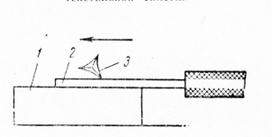
Fig. 10. Stripping the cable core from the oxide film: 1-metal stand, 2-core, 3-scraper
The stripped and twisted ends of the mounting wires are subjected to hot tinning: immersed electrically with molten solder G10C-40 or POC -61 for 1-2 sec. Preliminarily, the tinning site is covered with an acid-free flux, for example an alcohol solution of rosin.

Fig. 11. A device for twisting the cores of wires before irradiation 1 - guide bush, 2-clamping element, 3 - electric motor

Fig. 12. Securing the wire insulation with a thread (okletnevka): a-fixation of the first turn, b-laying of subsequent turns, c - tightening of the turns and cutting off the ends of the threads; 1-wire, 2 - cotton thread No. 20

Fig. 13. Securing the wire insulation with a piece of pipe: 1 - core, 2 - polyvinylchloride tube, 3 - insulation
Okletnevka consists in winding the thread layer on the insulation and in their corresponding fixation (Fig. 12). Okletnevku perform colored cotton or silk threads, which are then covered with glue BF-4 or nitro-lacquer. Using a semi-automatic machine allows to mechanize this process and dramatically reduce the laboriousness of the operation.
A more productive and qualitative way of sealing cotton insulation on the ends of the wire is sealing with chlorovinil, rubber or linoxin tubes (Figure 13).
To cut off the tubes of the required length, use the machine shown in Fig. 14. The machine operates on an automatic cycle. The productivity of its 300 thousand blanks per shift. It allows cutting pipes with a diameter from 2 to 6 mm into lengths from 8 to 20 mm.

Fig. 14. Cutting machine for insulation pipes: 1-chlorovinyl tube, 2 and 5 - guide bushings, 3 - pressure roller, 4 and 7-balls, 6 - knife, in-pinion gear, 9 - fixed knife, 10 - driving roller
The main parts of the machine are two gears, one of which is reinforced with a knife 6, and the second is a replaceable driving roller 10. A small pinion 8 is used to drive the gears, mounted on the motor shaft and rotating at a speed of 6000 rpm.
During operation of the machine, the chlorovinyl tubing passes through the guide sleeve 2 and, when it hits the replaceable drive roller 10, is pressed against the rubber pressure roller 3 and then fed into the second guide sleeve 5 and finally onto the blade of the fixed knife 9. With each revolution of the rotary knife, the chlorine vinyl the tube is cut off. Adjustment of the length of the cut pipes is performed by selecting a replaceable steel roller with a sharp crosscut knurling.
Nitroblank is filled with a wire of 8-10 mm in length (Figure 15).
When fastening the ends of the braid of wires to a BPVL, MGVL and MGVSL with nitro-lacquer or ochettnevka, the braid is first shifted by 3-5 mm from the cutoff point of polyvinylchloride insulation, and excess is dispersed along the wire.

Fig. 15. Fixing the insulation of the wire with nitrocellulose: 1-core, 2-nitro-lacquer, 3-insulation
When removing the insulation from the wires of the LPVL and MGVL by electric burning, the ends of the braid are sintered with internal insulation, so they do not need to be fixed.
Textile insulation of PVL wire is removed on a length of 8-10 mm from the place of cut of rubber insulation.

Fig. 16. Finishing the end of the shielded wire: 1 - core, 2-insulation, 3-shield braid

Fig. 17. Cutting of the end of the wire of BVVLE (BPShE, MGVLE, ICSLE): 1-core, 2-plaeticate insulation, 3 - textile braid
The ends of the shield braid are cut by 20 mm with mounting scissors, for this purpose the braiding edge is moved, the braid is cut along by 20 mm and carefully cut around so that the cut is even and without protruding veins.
The termination of the ends of the shielding braiding is performed in several ways:
- by pulling the end of the wire through a hole made in the braid and connecting the free end of the braid to the body lobe;
- soldered to braid additional wire; winding the braid of bare tinned wire and subsequent propaykoy this place;
- fixing the shielding and textile braids with threads, followed by coating with nitrocellulose and soldering to the middle of the shielding braid of the MHV wire (this method is used for short wires).
In the first case, proceed as follows: the end of the braid is expanded, shifting to the right, and at a distance of 20 mm from the end of the wire make a braid hole 3-4 mm in diameter; Through this hole, the wire is passed and removed from the braid, and the free end of the braid is pulled out and at the exit of the wire tightly pressed against the insulation. The end of the shielding braid is used to connect to the housing lobe. In the event that the length of the braid is not sufficient, by the end of the shielding braid, a section of bare MM wire 0.5-0.8 mm in diameter is brazed, the end of which is approximately 4-6 mm long and inserted into the braid from its end, crimped and brazed with POC-40 . In Fig. 188 shows a sample of such a seal.

Fig. 18. Termination of the earthing end of the shielding braid: 1 - MM wire. 2 - screening braid, 3-nitrocellular

Fig. 19. Soldering of an additional wire to the shielding braid: 1 - core, 2 - plastic insulation, 3 - nitroalk, 4 - wire МГВ, 5 - polychlorinated tubing (if it is necessary to isolate the shielding braid), 6 - shielding braid, 7 - cotton thread No. 20, 8 - textile braid
The method of soldering an additional wire to the shielding braid is shown in Fig. 19. Put a polyvinyl chloride tube on the braid and make a wedge-shaped cutout on it. At this point, the braided PCB-33 solder with the soldered end of the MGW wire 40-50 mm long, 0.35 mm2 cross-section, is soldered to the braid. After that, the place of soldering and the end of the shielding braid with the shifted end of the textile braid are fixed with thread No. 20 and covered with a filament-yarn.
The method of winding the additional wire onto the shield braid is shown in Fig. 20. At the end of the braid tightly wound 2-3 turns of bare tinned wire MM 0.5 mm in diameter. One end of this wire is pressed with mounting pliers to the braid, and the other (40-50 mm long) is left free. The turns of the wire are brazed to the braid by soldering the POS-33 soldering method. On the free end of the bare wire, put a linoxine tube, and the place of soldering is tightly closed with a piece of insulating tube 15-20 mm in length.
The ends of the shielding and textile braids are fixed with threads and nitrocellulose. The fluffed end of the MHV wire is soldered to the middle of the shield braiding with POP-33 solder. A chlorovinyl tube is put on the screened wire, and the free end of the soldered wire is passed through the slot previously made in the middle of the tube, and then pulled out.
Typically, the installation wires, laid in one direction, are tied into a common tourniquet with cotton or linen threads. The wiring harness is characterized by increased mechanical strength, reduces the dispersion of the circuit's own capacity and reduces the complexity of the installation operations.

Fig. 21. Termination of the end of the shielding braid together with the textile braid 1 - nitrocellulose, 2 - textile braid, 3 - cotton thread No. 20, 4 shielding light-weight

Fig. 22. Brazing of an additional wire to the shielding braid: 1-wire МГВ cross-section 0.35 mm2, 2-shielding braid, 3 polyvinylchloride tube
A sample of the rope is made at the design stage of the device. The following procedure is recommended. On a fully assembled and prepared for mounting chassis according to the installation diagram and the table of wiring connections lay out the wires. The ends of the wires are fixed on the contact lobes and labeled. The layout of the wires is carried out so that the finished bundle does not lie on the fasteners (nuts, screws, brackets, etc.) and, if possible, do not obstruct access to them; In addition, the insulation of the wire harness must not touch the contact lobes of closely spaced parts.

Fig. 20. Winding the additional wire on the shielding braid: 1-core, 2-insulator, 3-polyvinylchloride tube or tag, 4-wire MGV cross-section 0.35 mm2 or wire MM & 0.5 mm 5 - polyvinylchloride tube (if necessary to isolate the shielding braid) 6 - shield braid
Insulation of wires in places of passage of the bundle through the holes in the chassis and screens is protected by PVC pipes, gaskets, as well as special rubber sleeves (pistons) and insulators.
![]()
Fig. 24. Fastening of a thread on a plait: 1 - a string, 2 - a plait

Fig. 23. The wiring of the wires in the harness: I-wire, 2-plait, 3-wiring harness, 4-thread
First lay short wires and lastly the longest ones so that the latter form the face of the bundle. In the middle of the bundle, shielded wires are laid, not enclosed in polyvinylchloride tubes. If the TU in the harness provides spare wires, they are laid on top of the longest length of the harness.
It is necessary to provide a supply of wire along the length for fastening (20-25 mm to both ends) and the same stock for re-fastening the ends of the wires in case of breaks. Thus, in addition to the distance between the points of connection of the wire, in the direction of its laying is given another 40-50 mm. Before fixing the second end, measure the length of the wire, and the results are recorded in the table of mounting connections.
After the harness layout, the wires are tied with a strong thread using a curved needle; The loops should be knit with tension at regular intervals (no more than 20 mm), as well as at the branch points of the wires (Figure 23). Secure the beginning and end of the thread, as shown in Fig. 24.
When the binding of the bundle is completed, it is removed from the device and ruled on a flat surface; The branches of the bundle, located in different planes, are bent 90 ° into the plane of the main part of the bundle.

Fig. 25. Sketch of a bundle
Then the tourniquet is put on the sheet of drawing paper face-down and drawn in full size.
Excavation of the bundle is used to make an experimental template, which is a sheet of plywood with a strand drawn on it and pins in the right places (Fig. 26). The pattern is knitted by an experienced tourniquet, and the layout of the wires on the template starts with spare and long working wires and ends short, ie, the reverse order of the wire layout and the reverse image of the bundle are applied. This is done to give the harness a more neat look: the knots made on the harness will not be visible after it is placed in the appliance.
An experienced harness is checked by placing it on the chassis of the instrument, identifying and correcting the inaccuracies. Corrections are made in the sketch of the harness and the table of mounting connections. The working template is produced from the corrected sketch of the bundle.
In serial production, the tows are manufactured as follows: the mounting wires that have passed through the stripping, tinning and sealing of the ends are laid on the template in accordance with the connection table containing information about the brand, sections, serial numbers and wire coloring. Wire laying begins with fixing it on the starting pin.
Then the wire is laid according to the scheme of the bundle, bending it on the angled studs, and ending with the fixation on the final hairpin. The starting and ending studs have the same number. When all the wires are laid, they are tied with linen threads. The connected tourniquet is removed from the template and the probe is checked for the correct placement of the wires. The samples of the tows are shown in Fig. 27.
In those cases, when the mechanical strength and moisture resistance of the bundles are subject to increased demands, they are tied with a kip-band tape and impregnated with lacquer.
Electrified patterns that are widely used in radio plants are more convenient in work; they significantly reduce the laboriousness of the process of manufacturing the harness and reduce the possible marriage.

Fig. 26. Pattern for the layout of harnesses
In the electrified template, the end studs are replaced with push-buttons in which green warning lights are mounted. Sometimes the bulbs are located next to the clamps near the digital notation of the ends of the mounting wires. A connection table is placed on the template. Next to the designation of each connection, the red indicator lights are installed. The installation is powered by a voltage corresponding to the voltage of the signal lamps.

Fig. 27. Harnesses
Laying of mounting wires on the electrified template is as follows. When the template is turned on, two green lights of the terminals light up, between which the first wire needs to be laid. To fix the end of the wire, press the clamp button, opening the groove in which the wire is wound, the green signal lamp goes out. After laying the wire along the rope contour, fix the second end; the green light of the second button goes out, but the red control lamp on the connection table lights up, indicating that the wire is routed correctly. At the same time, two green light bulbs of those clamp buttons are lit, between which the next mounting wire is to be laid, etc. If the harness is laid correctly, only the control red tabs of the connection table will light.
At some radio plants, machines for laying out bundles have been developed.
The ends of the wires in bundles and inter-unit cables are marked using the insulation of wires of various colors, labels from multi-colored nitro-enamels, tips of colored or numbered PVC pipes, removable tags, polyvinylchloride adhesive tape on which figures are printed (bandage of marking tape is applied to wires and strands cable in 1,5-3 turns).

Fig. 28. Typical scheme of an electrified template
TECHNOLOGIES OF PRODUCTION OF ELECTRIC HARNESSS At the present time there are high demands on the quality of assembly and reliability. Accordingly, each unit and part of the car must meet these requirements. A component of the car is wiring (wiring harness). A wiring harness is a finished product consisting of individual wires fastened together in a bundle, the ends of which are reinforced with contacts that are assembled into pads or put on protective elements (tubes, rubber caps, covers). Wires in bundles are fastened: bandages from sticky PVC tape, cable ties (serrated clamps from thermoplastic polymers); heat shrinkable tubing. A modern car has harnesses with a total number of wire lengths of about three hundred (and often more) reinforced with various contacts. The reliability of such a complex product depends on several factors. First of all, these are increased requirements to the quality of components and materials. What, in turn, is influenced by the choice of the supplier and the conduct of the incoming control. The next factor is the use of modern high-performance and accurate production and control equipment that meets the requirements of international standards. And, finally, the most important factor of reliability are the specialists involved in the production process. Their quality and reliability depend on their professionalism. Autotractor harnesses can be divided into: wiring harnesses of low and high voltage (battery and starter wires are often single, less often - consisting of two or three wires).
  The technological process of manufacturing a wiring harness is divided into several basic operations: cutting wires, stripping the ends of wires from insulation, reinforcing wires with terminals or contacts, fastening wires into bundles (binding), installing plug connectors, checking quality. In order for you to better understand what components the wire harnesses consist of and in what sequence they are used in their manufacture, we tried to give a detailed description of the basic operations of manufacturing bundles and types of equipment, while being used. For a better understanding of the assembly sequence of any bundle in this section, we introduce general concepts of the bundle structure, which will be found later in the text. The harness can be divided into parts and given names to them.
 - The harness barrel is part of a bundle with the largest number of wires assembled in a bundle.
- Branch - a bundle of wires departing from the trunk of a harness or other branch.
- The branch point is the point of divergence of two or more bundles of wires at some angle (angles).
- Tips - elements allowing to mount and dismantle the harness with cold contacts.
- Connector devices - devices complete with terminals allow simultaneous connection of one or several pairs of "pin-socket".
- Protective elements - rubber products designed for mechanical and chemical protection of the connection point of the tip or connecting device with devices and other electrical equipment of the vehicle.
The bundle production of the 21st century requires new technological approaches in the production of wire harnesses. TERMOPRO offers new assembly tables for the layout and binding of the MONOLIT harnesses, which are designed to replace obsolete plywood plats in domestic enterprises.
Deprecated Solutions
Existing solutions are sheets of plywood, with a printed circuit diagram of the harness and rigidly fixed pins, at the nodal points of the bundles.
A new solution for the production of harnesses
The new tables for the MONOLIT harnesses are made of the Russian aluminum profile. Increased rigidity of the frame is provided by cast, angular amplifiers. The solid design of the tables for the manufacture of bundles is supplemented with elements for the rapid replacement of assembly plazas.
Compact table version
|
Inclined section table for laying and knitting harnesses 2000 х 1500 mmVery sturdy and rigid construction, but thanks to high-quality wheels with brake latch, the assembly table for bundles can be moved to any point in the workshop in a few minutes. To change the working platform it is necessary to manually unscrew only 4 nuts, which takes no more than a minute. |
|
The same inclined sectional table for laying and knitting of bundles(slope adjustment - horizontal or 60-80 degrees from the horizontal). |
|
The same table for the layout and mating of the bundles with the lowered subframeTwo connected tables. In the production of wiring harnesses, such tables can be combined into groups of several pieces for binding long-length bundles. |
|
The horizontal sectional table for the layout and binding of the harnesses is of any length.Section tables for the production of large length harnesses are delivered on adjustable supports and combined into a monolithic structure directly in the production room. |


Flexible solution
The production of bundles on replaceable plazas of two types increases the flexibility in the manufacture of bundles, and also reduces the downtime when changing over to products with a different structure of the harness.
Russian production
The company TERMOPRO produces modern tables for the manufacture of harnesses in accordance with the requirements of your terms of reference. We are ready to adapt the available solutions for you. There are no restrictions on the dimensions of the tables - length, width, height. We will do so - how convenient it is for you!
Send your good work in the knowledge base is simple. Use the form below
Students, graduate students, young scientists who use the knowledge base in their studies and work will be very grateful to you.
Posted on http://www.allbest.ru/
1. Technical characteristics of the production facility
The technical characteristics of the production facility, to which this process is developed, is the manufacture of bundles.
General information on harnesses and technology of their manufacture
The wiring is an electrical installation of EVA units using volumetric insulated wires combined in a bundle.
The design of the harnesses is determined by the features of the framework designs and the requirements for maintenance and repair of the equipment. The bundles are divided into interblock and intra-block, which, in turn, are subdivided into flat, volumetric, with movable branches.
Distinguish them and the degree of complexity: the number of branches and closed branches. The plugging is carried out with the help of installation wires and cables of various types and purposes. Wire insulation can be fibrous from nylon threads (MSDL, MGSh, MGSHD) or fiberglass (MGSL, MGSLE); Polyvinylchloride (PMV, MHV) and fibrous-polychlorovinyl (LSH, MGSHV, LPBL), plastic in the form of a shell of polyvinylchloride (MKSH, MPKSH); rubber (LPRGS, PRP, APRF, PWG) and fluoroplastic (MGTF). The choice of insulation is determined by the electrical voltage and operating conditions of the equipment.
At normal temperature and humidity wire with fibrous or PVC insulation is used, at elevated temperature and humidity - with insulation from fiberglass or fluoroplastic.
In case of necessity of protection from external electrostatic fields, installation is carried out by shielded wires and cables with obligatory earthing of each screen.
Part of the installation wires and, in the first place, with rubber insulation are supplied with tinned conductive wires. This keeps the electrical resistance and mechanical resistance of the copper wire located in the rubber or vulcanized rubber, and speeds up the preparation of wires for mounting and soldering.
When designing, tolerances for harness parameters can be determined analytically. When calculating the size chain, take the wire with a reserve for soldering and compensate for bends in the contact connections. Deflections of the closing link must take into account tolerances on the geometric dimensions of the frame, fastening - bundle, the length of wires in the layout, the installation of technological pins on the template.
Initial design of the rope construction is carried out as follows. On the assembled frame lay the wires according to the installation or concept. The ends of the wires are marked on both sides by tags indicating the route number (^ -2; 1 -6; 3 -5 etc.), after which their length is measured and data is entered into the table of mounting connections.
The sketch is used to develop a template and. in particular, to determine the location of technological pins. On the template, the assembly of the test harness is assembled, and after its installation on the frame, the template is corrected.
2. Technology analysis
Technological design is a design that, with minimal cost, is the simplest in manufacturing. The technological design should include:
1. The widest possible use of standardized units, standardized and normalized parts of component parts;
2. Perhaps fewer details of original and complex shapes and different names, as well as greater repeatability of the same parts;
3. Creation of rational parts with easily accessible surfaces for processing and sufficient rigidity in order to reduce labor intensity and cost of the whole product;
4. The rationality should be the assignment of the accuracy of the size and class of surface roughness;
5. Presence of details on the base surfaces;
6. The most rational way of obtaining blanks for parts (castings, stamping with dimensions and shapes, perhaps closer to the finished parts, ie providing the highest coefficient of material use and the least amount of labor);
7. Complete elimination or possibly less use of fitting and fitting work during assembly by making interchangeable parts and mechanization, automating assembly work;
8. Simplify assembly and the possibility of parallel in time and space assembly of individual parts of the product;
9. The design should be easy to assemble and disassemble, and also provide access to any mechanism for adjustment, lubrication, repair.
The developed design is technological, because it provides:
1. Perhaps a smaller number of parts of the original and complex shape and different names, as well as greater repeatability of the same parts;
2. Creation of rational parts with readily accessible surfaces for processing and sufficient rigidity in order to reduce labor intensity and cost of the whole product;
3. Simplified assembly and the possibility of parallel in time and space assembly of individual parts of the product;
4. Complete elimination or possibly less use of fitting and fitting work during assembly by making interchangeable parts and mechanization, automation of assembly work.
3. Technological route of manufacture of a plait
The technological route for manufacturing the harness is the following sequence of operations:
1. Preparatory operation
2. Package Contents
3. Preparation of mounting wires
4. Layout of wires on the template
5. Harness of the harness
6. Control
4. A detailed description of the main operations
1. Preparatory operation
2. Package Contents
3 . Ppreparation of mounting wires
Preparation of installation wires consists of the following operations: dimensional cutting, removal of insulation and sealing of the ends of wires, marking, maintenance and wire twisting. If the technological process provides a continuous layout of the wire on the template, then cutting, removal of insulation and sealing ends are made after the formation of the bundle.
Wire cutting manually is done with simple tools (scissors, cutters), determining the length of the wire according to the pattern or using a ruler. In serial production, this operation is automated. Universal are automatic machines for dimensional cutting and simultaneous removal of insulation from the ends of the wire.
Depending on the type of insulation, different methods of stripping are used: an incision , electric ignition or thermal softening from subsequent mechanical tightening of the insulation, and certain ways of sealing the ends of the wires.
Textile, plastic and film insulation is removed by incision or by electric burning. Removal of multi-layer insulation has a number of features. So, in the presence of fiberglass, the outer plastic insulation is removed by electric ignition, and the inner (glass fiber) is untwisted, twisted and cut at a distance of 1 mm from the end of the external insulation. Outer textile braids require a step-by-step cutting of the ends of the wires. For example, a piece (3-10 mm) of polyvinylchloride or rubber insulation is left between the cotton braid and the wire. The end of the braid is fixed with glue, an insulating tube or a thread band covered with glue.
Stripping of heat-resistant fluoroplastic insulation is carried out by electric heating at an elevated temperature of the filament. In this case, a toxic gas is released - fluorine, which must be removed from the working area by means of a suction system.
The stripping should preserve the quality of the insulation that can not be removed, exclude the incision or breakage of current-carrying veins and be sufficiently productive. In addition to machines for cutting wires and removing insulation, special devices for thermomechanical stripping have been developed. Their main working elements are filament and sponge knives.
The thread burns the insulation when the wire rotates around its axis. Sponges are the support for the wire when burning insulation, protect it from charring and thread from mechanical damage, provide a thread together with the thread insulation. The working edges of the jaws have a rounding radius of 0.08 mm and are polished, which will eliminate the incision, and the breakage of live conductors. Insulation strippers - can be equipped with a connection device to the vacuum system for suction of toxic insulation products. The thermomechanical method makes it possible to remove the insulation in one step from wires with a cross section of 0.07-0.35 mm 2.
For installation, use shielded wires and radio frequency coaxial cables that have an outer polyvinylchloride coating on top of the shielding braid. The separation of the coating by the notch is laborious and does not provide a high quality cutting of the ends.
The thermomechanical method allows to remove plastic insulation within 2-3 seconds without damaging the braid.
Sponge knives , equipped with heaters, penetrate through the insulation and cover the diameter of the shielding braid. The insulation area inside the sponge heats up and expands, which makes it easy to remove it by pulling it off the end of the wire.
Further splitting of the ends of the shielded wires consists in removing a shielded braid in a certain area. One way to remove is the circular cut-off of the braid using a punch-matrix cutting pair
The working part of the punch is made in the form of a cone, passing into the sphere, which allows it to move easily inside the braid and provides a smooth cut of the end of the screen on the sharp edges of the die . The method is realized with the help of various devices designed to cut off in 3-4 seconds.
There are other ways to remove the shielding braid: the screw section with rotating mills and knives, cutting off the ring thickening of the braid.
To remove the end of the insulated wire through the shielding braid with a sharp tool, the vein is moved apart: braids and a wire is pulled through the formed hole. The most common tool is a grooved needle that is inserted from the end of the shielded wire between the braid and the insulated wire. At a certain point, the needle spacing is pulled apart by the braid and the end of the wire is pulled using the needle eye. This operation is carried out for 3-4 s manually, directing the needle with simple devices.
The termination of the ends of the shielded wires is to ground the shields or fix the end of the braid to the wire. The grounding is carried out by attaching the free end of the braid to the frame elements, by soldering the additional wire, by applying a band of bare tin-plated wire, followed by its soldering. Soldering places are protected with insulating pipes.
A non-grounded braid is sealed between two insulating pipes, placing one under the shield, and the other outside or between the layers of the insulation tape. The end of the braid is fixed with a thread bandage or wire bandage followed by a soldering.
After stripping, the exposed ends of the wires are stripped, and the stranded wires are twisted at an angle of 15-300 to the wire axis. The latter operation is performed manually (section of the vein less than 0.11 mm 2), pliers or with the help of special devices. The prepared ends of the wires are subjected to hot treatment by immersion in a bath with solder.
The marking of the wires is necessary to facilitate installation, monitoring, troubleshooting and repair. Wire with colored insulation is used and labeled with tags, sticky mites or by applying the markings directly to the insulation of the wires. Wires with colored insulation are usually used for internal installation of EVA. On wiring diagrams indicate the color of the mounting wires with abbreviated notations or digital ciphers. Marking of wires with sticky tapes consists in applying bandages from this tape to the ends of the wires. The greatest use was received by marking with the help of marking tags made of PVC pipes. The tag is attached to the end of the wire. In this case, the tag must overlap the edge of its insulating braid for 1-3 mm. The tags are put on the wires in such a way that they do not slip when they are shaking and vibrating.
The symbols on the surface of the marking tags are specified in the wiring diagrams and are carried out in accordance with industry standards. Production of tags (marking, drying, cutting) is performed on special machines. The wiring wires are wired to eliminate electrical interference and reduce the mutual influence of the circuits. The swing pitch is 10-40 mm and increases depending on the increase in the cross-section of the wire (0.05-0.75 mm 2). This operation is performed manually with a drill or on special machines.
4 . Layout of wires on the template
wiring harness insulated wire
Structural and technological testing of the harness makes it possible to manufacture it outside EVA by laying out the installation wires and cables on the template. Depending on the configuration of the bundles, flat or three-dimensional patterns are used. The flat pattern is the base on which, according to the trace (see Figure 2) and the configuration of the bundle, there are metal studs. Between the studs, the installation wires are laid. To protect the wires from damage, insulating tubes are put on the studs. To fix the ends of the wires in the design of the template are provided holes located near the pins, or special clamps. The volumetric template has additional elements, allowing to conduct a layout of wires and fixing them in three planes.
There are universal flat patterns that have holes located at a certain step and designed to install studs. The layout of the studs on the template can be changed depending on the routing and configuration of the harness.
Designs of electrified templates have been developed, which increase the production capacity of the bundles and eliminate erection errors. On this pattern, the ends of the mounting wires are fixed with special clamps electrically connected to the signal (green) and control (red) lamps. Lamps and button clamps are switched in such a way that when the template is turned on, the two lamps of the first trace light up. With the correct laying and fixing of the wire, the lights of the second route light up, etc. Electrified patterns are more expensive than conventional ones, and it is advisable to use them in the production of EVA.
When laying wires on templates, some general rules are defined. From the wires of different cross-sections, several bundles should be made by combining wires that are close in diameter. insulation (for example, from 1 to 3 and from 3 to 6 mm). Shielded drives must be located inside the harness, so they begin the layout. Screens are preliminarily cut and soldered, in the presence of an outer metal braid, it is wrapped with a keeper's tape or insulated with a tube. Inside the bundle, short wires of small cross sections are laid. Long wires are laid from the outside with the formation of the front side. Spare wires must be on top with access to their ends. These rules are fairly easy to perform when manually arranging.
The sequence of the layout of wires on the template is manually set by the table "of connections taking into account the listed rules. Often, a template is placed on the template with the designation of the traces. The end of the wire wound off the bay is marked with a tag and fixed on the template. The wire is cut in place after the layout between the studs and marks its end. These transitions are repeated many times. Finishing of the ends with this sequence of operations is carried out after the bundle is knitted. The manual layout on the template is made by the installer, and it is very laborious. In a series production, it can be mechanized with a software controlled device.
5 . Binding of harnesses
Two (and more) of insulated wires with a length of more than 50 mm parallel to one path must be connected in a bundle. An exception can be only an unacceptable increase in mutual interference in electrical circuits. For knitting, we use threads, cords, braid, insulation tapes, shrink tubes, etc. The operation is carried out, as a rule, on a template. Step knitting t depends on the wire cross-section, the number of wires n and diameter D harness. On the curved sections, the pitch should be reduced, depending on the bending diameter of the bundle. In places of branching of wires, the mating should have 2-5 turns on all branches, the bandages should be made of 2-3 adjacent loops. The ends of the harness should have bandages and terminal nodes.
The mating is carried out in one, two threads and more with a tension manually or with the help of tools. To reduce labor intensity, the process of tying the bundles is mechanized using pneumatic pistols, and sometimes automated, making knitting of bundles on special semi-automatic machines.
To protect against mechanical damage, the harness along the entire length or in a certain area is wound with an insulating tape. If it consists of wires with cotton or silk insulation, then the tow is impregnated with a water repellent to protect it from moisture.To protect it from heat or corrosive environments, the strands are placed in tubular, tape, strip or braided shells, they are put on by hand or on the machine after removing the harness from the template.Thus, the binding of the harnesses is no less labor-intensive than the layout and marking of the wires.
In addition to the use of various devices to mechanize the manufacture of the harness, it is advisable to use conveyor lines in a serial production. In this case, the technological process is divided into a number of small operations. At each workstation, the layout of wires of the same cross section and brand is fully implemented. When determining, the stroke of the conveyor is oriented to the operation of the layout, proceeding from the fact that it is easier to subordinate the binding operation to the chosen rhythm. For example, the binding of 16-24 loops takes 3-5 minutes. Most often, the operation time is 5 or 7.5 minutes.
The conveyor method for manufacturing the tows also has other features. Wiring is carried out continuously, winding them off the reels. At the end of the wire, a set of tags is preliminarily put on to mark all the traces that are performed at this workplace.
Apply universal templates, equipped with studs both in places of kinks and branches, and in places of the subsequent cutting of wires. Layout traces are marked with special stencils placed on templates. For the binding of bundles, threads are used that can withstand sufficiently large tension forces. After knitting, wire cutting, removal of the tow from the stencil and cutting of the ends follows.
The conveyor for making the tows is located in a horizontal plane, closed and conveys the templates by means of trolleys. In addition to the templates, it is equipped with pistols for binding the bundles, with tools for stripping, with a tinning plant. The conveyor method simplifies the operations performed at each workplace, and allows to reduce the overall laboriousness of manufacturing the bundles. Disadvantages of it are the tension of the wires during the layout and the deformation of the bundle after removal from the template, which worsens the quality of the mating.
6 . Tocontrol
After the manufacture of the bundle, the quality of the termination of the wires and shields, the presence of marking, the absence of damage to current-carrying veins and insulation, the quality of tinning are controlled. The integrity of the electrical circuits is checked by a probe with probes. In the chains with a large number of intermediate compounds, the resistance is measured.
During the inspection, the ribbon cables are checked for the absence of wire breaks, insulation resistance between the conductors and ground buses, the presence of electrical connections between the connectors' contacts and the ribbon cable.
For monitoring, special automated stands have been developed, for example, with the number of points to be checked 90 and the main technological time for testing the product is not more than 30 s. The control is performed by checking the electrical circuits, comparing the states of the switches and then transferring the results to the light indication panel. Stands can work in automatic and manual modes.
Hosted on Allbest.ru
Similar documents
Characteristics and technical parameters of the thyristor, its varieties, the principle of operation, conventional designation and application. The device autotransformer, the principle of its operation. Maintenance and repair of electric motors. Drawings of bundles, cables and wires.
crib, added 20/01/2010
Installation, connection and termination of wires and cables, cable couplings. Connection of wires by crimping, twisting with subsequent soldering and shrouding. The device and the principle of operation of a fluorescent lamp. Marking of diodes, thyristors, resistors.
report on practice, added on 03/26/2013
Preparation of routes for wirings. Overview of the types of wirings. Cutting wires and cables. Connection and termination of wires. Organization of installation of electric wiring of an apartment house. Installation of various types of wirings. Occupational safety and health.
term paper, added on August 27, 2010
Classification of wirings. Organization of installation of wirings. Connection and termination of wires. Quality control of contact connections. Methods of installation of open wireless wirings, tubular wires, wirings on trays and boxes.
term paper, added on August 27, 2010
Power, lighting, trunking and distribution electrical wiring. Rules for the installation and maintenance of wirings, electrical installations, power shields; primary requirements. Installation of tins in control panels; laying wires with air bags.
course work, added 17/03/2012
Power cables and wires - winding, installation, installation: technical requirements, purpose, marking and application. Insulating materials used for installation wires. Marking of wires according to GOST. Control and special cables.
summary, added on 06/05/2008
Stages of full assembly of electrical equipment. Calculation of the load power. Open cable laying on the building base with the use of staples. Installation of steel pipes and wires, low-voltage complete devices and ballasts.
thesis, added on 09/04/2010
Advantages and disadvantages of incandescent lamps, their types and applications, device and operation. Marks and characteristics of wires and cables used for electrical work. Applied mechanisms, tools and adaptations; installation of incandescent lamps.
summary, added on July 22, 2010
The advantages of fluorescent lamps, their types and applications, the device and the principle of operation. Marks and characteristics of wires and cables used for electrical work. Applied mechanisms, tools and adaptations; installation of fluorescent lamps.
summary, added on July 22, 2010
Requirements for the installation of protection devices that are unstable to the maximum current values. The technology of mounting the power box: marking the place of installation of electrical equipment, fittings and flaps, punching holes, installing fasteners, laying wires.