Antipyretics for children are prescribed by a pediatrician. But there are emergency situations for fever when the child needs to be given medicine immediately. Then the parents take responsibility and use antipyretic drugs. What is allowed to give to infants? How can you bring down the temperature in older children? What medicines are the safest?
In the process of repair work, it often becomes necessary to determine the route of hidden wiring. The absence of its scheme complicates this task somewhat. As practice shows, in 90% of cases, the owners of a private house or apartment did not have such a scheme initially, or it was lost. A wiring finder will help solve the problem.
So looking for hidden wiring
Wiring searchers are usually divided according to the principle of operation, there are four of them:
- electrostatic;
- electromagnetic;
- metal detector;
- combined.
Each of them has its own characteristics that determine the scope of use.
Electrostatic devices
Searchers of this type register the presence of an electromagnetic field emanating from wires to which voltage is connected. This is a fairly simple device that is easy to assemble with your own hands (the device diagram will be given in the final section). Note that almost all inexpensive detectors operate on this principle.

The peculiarities of this class of devices include the fact that they react to any metal in the walls. That is, in addition to wiring, the detectors will be triggered when fittings, screws, nails, etc. are detected.
Combined finders
Devices of this type are multifunctional devices - multidetectors. They can combine several principles of searching for wiring hidden in the wall, which significantly expands the scope and increases efficiency.
An example is the TS-75 model shown in the photo below. This device combines the functions of a metal detector and an electrostatic detector.
Note that home-made hidden wiring finders often outperform inexpensive Chinese devices in terms of performance.
Do-it-yourself hidden wiring finder
In this section, we will give as an example several wiring finder circuits that even novice radio amateurs can assemble. Let's start with the most elementary device.

Schematic: Simple FET Wiring Detector
From the details we need: a field effect transistor, KP303 or KP103 is suitable (the letter index does not matter), a telephone speaker with a resistance of 1600 to 2200 ohms and an ohmmeter (used as an indicator).
The body of the transistor plays the role of an antenna, they are carried along the wall. When the wiring is detected (it must be energized), the speaker will display a characteristic sound at a frequency of 50 Hz, and the indicator arrow will deviate.
Unfortunately, the sensitivity of such an indicator leaves much to be desired, so let's consider a more complex scheme.
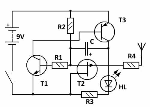
Schematic: three-transistor seeker
The list of required radio elements:
- transistors (any index will do): T1-KT315, T2-KP103, T3-KT361;
- LED HL-AL307B or any equivalent;
- resistance parameters: R1 - 2.2 kOhm, R2 - 10.0 kOhm, R3 - 470 Ohm, R4 - 1.0 MΩ;
- capacitance C -10.0 uF 10 V.
As an antenna, you can use a copper wire of appropriate thickness with a length of 80 to 100 mm (the longer the length, the higher the sensitivity)
The two devices above do not provide the ability to adjust the sensitivity, which will somewhat complicate the search for wiring. Below is a diagram where this function is implemented.
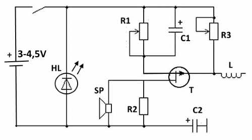
Schematic: Adjustable Sensitivity Finder
Designation of parts on the diagram:
- T - KP103;
- HL - AL107BL (can be replaced with an analogue);
- R1-2.0 kOhm;
- R2 -2.0 kOhm (you may need to adjust it to achieve maximum volume);
- R3- 1.0 MΩ;
- C1 -5.0 uF;
- C2 - 20.0 uF
- SP - speaker with resistance from 30 to 60 ohms;
- L - contains from 20 to 50 turns of wire with a diameter of 0.3-0.5 mm per 3 mm frame, frameless execution is allowed.
In conclusion, we present a scheme of a combined instrument, which combines the functions of a metal detector and an electrostatic detector.
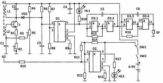
List of radio components:
- coils for antenna A1: L1 - 60 turns, L2 - 5 turns, wire diameter from 0.12 to 0.16 mm, a ferrite rod (600НН) Ø10mm is used as a frame, its length should be within 50-60 mm;
- T1 - KT315 (letter index does not matter);
- D1, D2 - KR140UD1208;
- D3 -K561LE5;
- HL1, HL2 - KIPMOB1B-1K;
- VD1 - KD522;
- capacitances: C1 and C4 - 0.1 μF, C2 - 1.0 μF, C3 - 0.022 μF, C5 - 0.033 μF, C6 - 1.5 μF;
- resistances: R1 and R19 - 1.0 kOhm, R2 - 4.7 kOhm, R3 - 15.0 kOhm, R4 and R18 - 100.0 kOhm, R5 - 47.0 kOhm, R6 - 1.0 MΩ, R7 - 130.0 kOhm, R8 and R12 - 200.0 kOhm, R9 - 36 kOhm, R10 and R17 - 510 Ohm, R11 - 2.0 kOhm, R13 - 910.0 kOhm, R14 - 160.0 kOhm, R15 - 680 .0 kOhm
Switch SW1 is used to switch the multi-detector operation modes between a metal detector and an electrostatic wiring indicator. If the latter is on, then when the A2 antenna approaches the place where the live wire is laid, the LED turns on (it starts blinking at a frequency of 50 Hz).
In the metal detector operating mode, when a metal object is affected by the inductance field of the antenna A1, HL1 starts to burn, and in the piezoceramic emitter SP, a sound signal with a frequency of 1 kHz repeating with a period of 2 seconds is heard.
Of course, the schemes presented above are far from perfect, but their sensitivity is quite enough for domestic use.